Case 845B 845B DHP 865B 865B VHP 865B AWD 885B 885B DHP 885B AWD Grader Power Train Service Manual (84559575) – PDF Download
Original price was: $40.95.$14.95Current price is: $14.95.
Case 845B 845B DHP 865B 865B VHP 865B AWD 885B 885B DHP 885B AWD Grader Power Train Service Manual (84559575)
Size : 16.6 MB
Format : PDF
Language : English
Brand: Case
Type of machine: Case Motor Grader
Type of document: Service Manual
Model: Case 845B 845B DHP 865B 865B VHP 865B AWD 885B 885B DHP 885B AWD Grader
Part No:84559575
Description
Case 845B 845B DHP 865B 865B VHP 865B AWD 885B 885B DHP 885B AWD Grader Power Train Service Manual (84559575)
File Details:
Case 845B 845B DHP 865B 865B VHP 865B AWD 885B 885B DHP 885B AWD Grader Power Train Service Manual (84559575)
Size : 16.6 MB
Format : PDF
Language : English
Brand: Case
Type of machine: Case Motor Grader
Type of document: Service Manual
Model: Case 845B 845B DHP 865B 865B VHP 865B AWD 885B 885B DHP 885B AWD Grader
Part No:84559575
CASE 845B 845B DHP 865B 865B VHP 865B AWD 885B 885B DHP 885B AWD GRADER POWER TRAIN SERVICE MANUAL (84559575) – PDF DOWNLOAD:
Image Preview:
Sample Page From The Manual:
Case 845B 845B DHP 865B 865B VHP 865B AWD 885B 885B DHP 885B AWD Grader Power Train Service Manual (84559575).
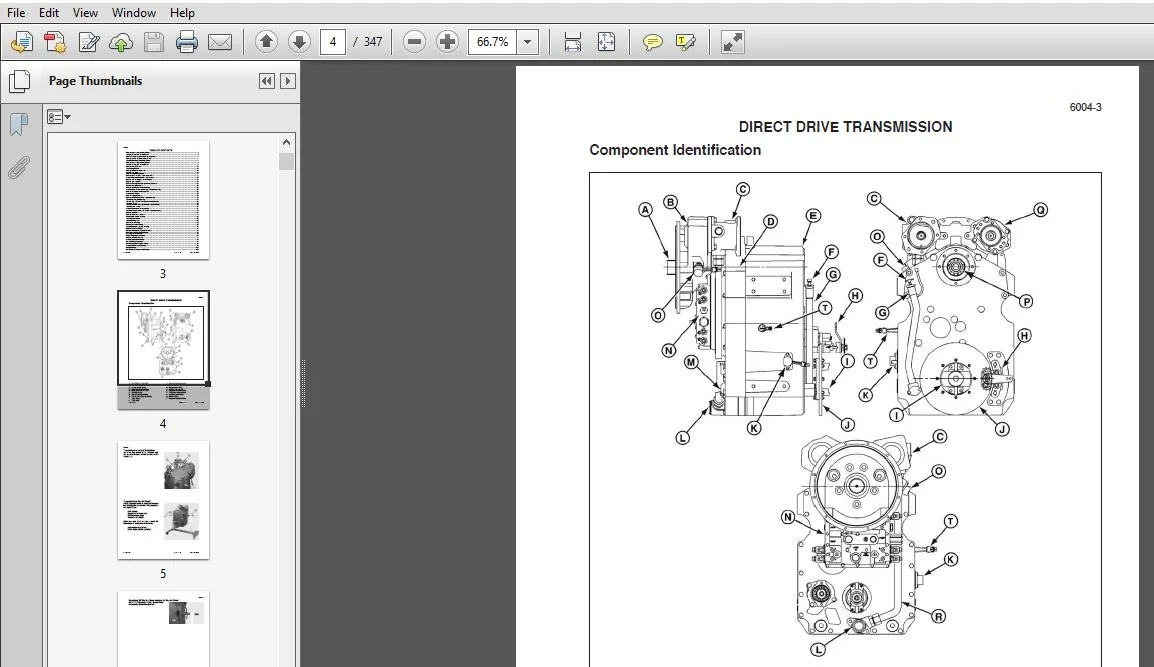
- Direct Drive Transmission The engine is directly connected to the input shaft of the transmission. When the transmission is engaged into gear the engine power is connected to the output shaft of the transmission at different speed ratios depending on which directional and speed clutches are engaged. Each clutch is engaged hydraulically and controlled by an individual proportional valve. The rate of the pressure rise behind each clutch piston is determined by the Transmission Control Unit (TCU) providing the current to each valve.
- The engine power may be disconnected from the transmission output shaft by depressing the clutch pedal or by shifting the transmission to the neutral or park position. The transmission charge pump and vehicle pumps are always connected to the engine power via a constant mesh gear train. A torsional damper may be installed between the engine and transmission input shaft to detune the system from harmful resonant frequencies
Tabe of Contents:
Case 845B 845B DHP 865B 865B VHP 865B AWD 885B 885B DHP 885B AWD Grader Power Train Service Manual (84559575)
Remove Upper Magnetic Pickup Sensor…………………………………………………………………………………………………………………6
Install Upper Magnetic Pickup Sensor…………………………………………………………………………………………………………………….6
Remove Cylinder Magnetic Pickup Sensor (MPU)……………………………………………………………………………………………………7
Remove Cylinder Magnetic Pickup Sensor……………………………………………………………………………………………………………..7
Install Cylinder Magnetic Pickup Sensor…………………………………………………………………………………………………………………7
Remove Lower Magnetic Pickup Sensor…………………………………………………………………………………………………………………8
Install Lower Magnetic Pickup Sensor…………………………………………………………………………………………………………………….8
Remove Wiring Harness……………………………………………………………………………………………………………………………………..10
Install Wiring Harness…………………………………………………………………………………………………………………………………………10
Remove Suction Tube Assembly………………………………………………………………………………………………………………………….13
Install Suction Tube……………………………………………………………………………………………………………………………………………15
Remove Charge Pump Group……………………………………………………………………………………………………………………………..17
Remove Driven Gear And Bearing Assembly…………………………………………………………………………………………………………17
Theory of Operation Direct Drive Transmission………………………………………………………………………………………………………20
Remove Input Housing and Input Assembly…………………………………………………………………………………………………………..22
Remove Input Assembly……………………………………………………………………………………………………………………………………..23
Remove Coupling Shaft and Input Bearing Retainer……………………………………………………………………………………………….25
Disassemble Input Housing…………………………………………………………………………………………………………………………………27
Remove and Disassemble Driven Gears………………………………………………………………………………………………………………28
Assemble Driven Gears and Bearings (Charge Pump Side)…………………………………………………………………………………….29
Remove Idler Gears and Disassemble………………………………………………………………………………………………………………….29
Assemble Idler Gears…………………………………………………………………………………………………………………………………………30
Remove Magnetic Pickup……………………………………………………………………………………………………………………………………30
Remove Direct Drive Input Housing And Bearing……………………………………………………………………………………………………32
Install Oil Seal and Ball Bearing…………………………………………………………………………………………………………………………..33
INSTALL IDLER GEARS AND BEARING ASSEMBLIES…………………………………………………………………………………………35
Install Idler Shafts………………………………………………………………………………………………………………………………………………36
Install Driven Gear Assembly (Auxiliary Pump Port Side)………………………………………………………………………………………..38
Install Magnetic Pickup……………………………………………………………………………………………………………………………………….40
Assemble Direct Drive Input Assembly………………………………………………………………………………………………………………….41
Install Input Housing Assembly to Main Case Front Housing……………………………………………………………………………………43
Proportional Valves…………………………………………………………………………………………………………………………………………….45
Remove Control Valve Groupe…………………………………………………………………………………………………………………………….47
Iinstall Gasket to Front Housing…………………………………………………………………………………………………………………………..55
Install Plate and Gasket………………………………………………………………………………………………………………………………………55
Install Valve Assembly………………………………………………………………………………………………………………………………………..56
Remove Front Housing……………………………………………………………………………………………………………………………………….63
Disassemble Front Housing………………………………………………………………………………………………………………………………..65
Install Front Housing To Rear Housing………………………………………………………………………………………………………………….69
REMOVE OUTPUT GROUP……………………………………………………………………………………………………………………………….71
Disassemble Output Group and Oil Trough……………………………………………………………………………………………………………72
Remove All Clutch Stage Assemblies……………………………………………………………………………………………………………………73
First Stage Shaft Assembly…………………………………………………………………………………………………………………………………75
Second Stage Clutch Assembly…………………………………………………………………………………………………………………………..76
Third Stage Clutch Assembly………………………………………………………………………………………………………………………………77
Fourth Stage Clutch Assembly…………………………………………………………………………………………………………………………….78
Fifth Stage Clutch Assembly………………………………………………………………………………………………………………………………..79
Disassemble Clutch Stage Assembly……………………………………………………………………………………………………………………80
Assemble Clutch Stage Assembly………………………………………………………………………………………………………………………..92
Sizing Seal Rings…………………………………………………………………………………………………………………………………………….102
Rear Housing Component Identification………………………………………………………………………………………………………………108
Please Note:
- This is the same manual used by the DEALERSHIPS to SERVICE your vehicle.
- The manual can be all yours – Once payment is complete, you will be taken to the download page from where you can download the manual. All in 2-5 minutes time!!
- Need any other service / repair / parts manual, please feel free to contact us at heydownloadss @gmail.com . We may surprise you with a nice offer