Case 9020 Excavator Parts Catalog Manual 8-8941 – PDF DOWNLOAD
Original price was: $86.95.$29.95Current price is: $29.95.
Case 9020 Excavator Parts Catalog Manual 8-8941 – PDF DOWNLOAD
Description
Case 9020 Excavator Parts Catalog Manual 8-8941 – PDF DOWNLOAD
DESCRIPTION:
Case 9020 Excavator Parts Catalog Manual 8-8941 – PDF DOWNLOAD
Indexes
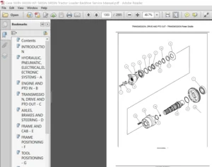
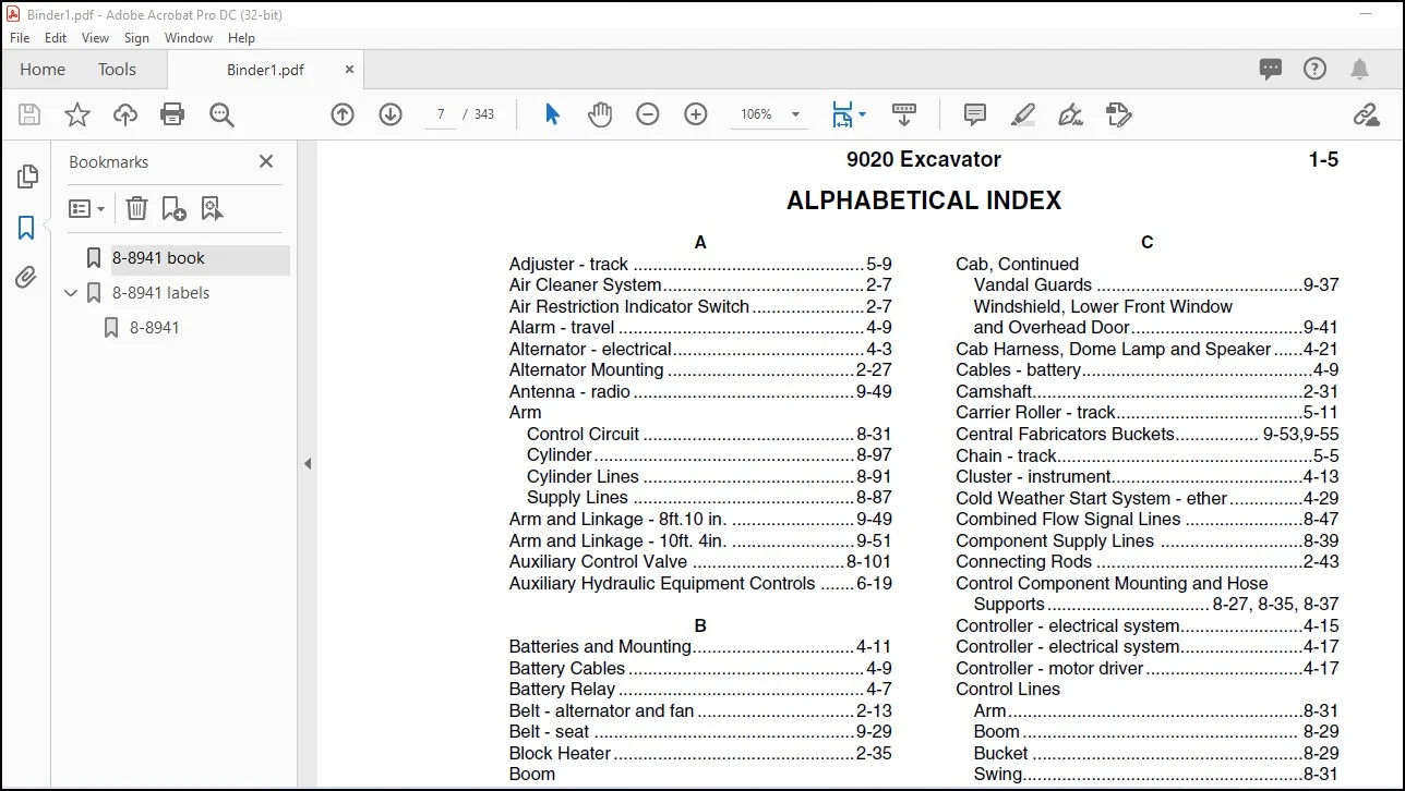
Section 1 of this catalog contains a SN and PI N. location guide, alphabetical index, pictorial index of the sections included, and pictorial index(es) for quick location of hases and tubes (and other system components in some catalogs) An alphabetical index siso appears at the beginning of each section Section 10 is the Numerical lndex which lists ali part numbers in alpha/numeric arder with their page location and reference number.
lllustration and Text
The arrangement of this parts catalog is for easy identification of parts Ali parts are iliustrated in “exploded views” in proper relation to each other. Reference numbers used in the iliustrations reter to those on the text pages. The text pages list reference number, part number, part description ahd the quantity required.
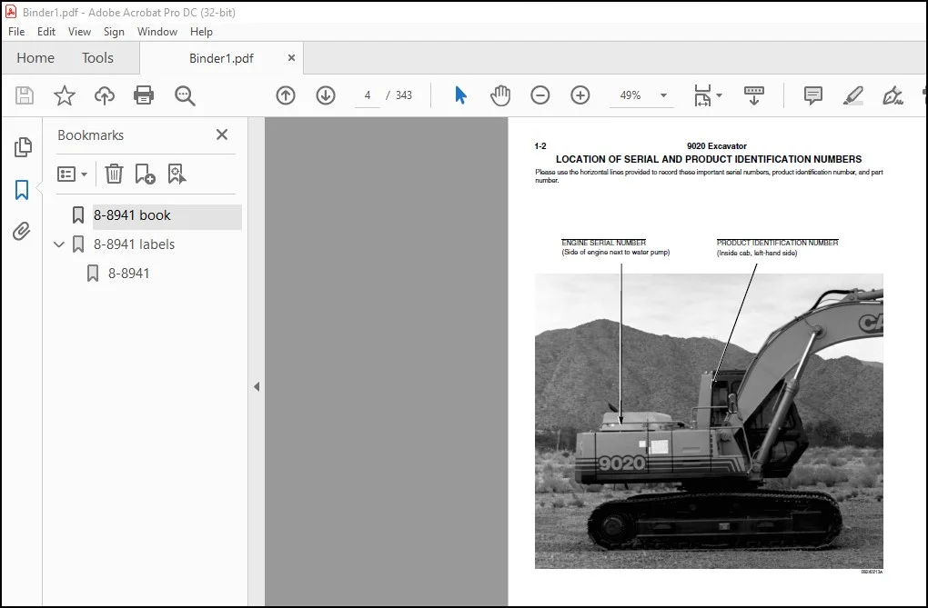
P.I.N. “Product Identification Number”
SN “Serial Number”
NSS “Not Serviced Separately” in the part number
column indicates this part is not available for service.
REF “Reference” in the part number column indicates
this part has special service information. The
page where this information can be found is given
in the part description column.
UAR “Use As Required” in the quantity required column
indicates the number of parts used is determined
by service needs.
TABLE OF CONTENTS:
Case 9020 Excavator Parts Catalog Manual 8-8941 – PDF DOWNLOAD
GENERAL 1
ENGINE 2
FUEL 3
ELECTRICAL 4
STEERING 5
POWER TRAIN 6
HYDRAULIC 8
CHASSIS 9
NUMERICAL INDEX 10
A
Adjuster – track ……………………………………….. 5-9
Air Cleaner System………………………………….. 2-7
Air Restriction Indicator Switch…………………..2-7
Alarm – travel ………………………………………….. 4-9
Alternator – electrical………………………………… 4-3
Alternator Mounting ………………………………..2-27
Antenna – radio ………………………………………9-49
Arm
Control Circuit …………………………………….8-31
Cylinder……………………………………………..8-97
Cylinder Lines …………………………………….8-91
Supply Lines ………………………………………8-87
Arm and Linkage – 8ft.10 in. …………………….9-49
Arm and Linkage – 10ft. 4in. …………………….9-51
Auxiliary Control Valve …………………………. 8-101
Auxiliary Hydraulic Equipment Controls …….6-19
B
Batteries and Mounting……………………………4-11
Battery Cables ………………………………………… 4-9
Battery Relay ………………………………………….. 4-7
Belt – alternator and fan …………………………..2-13
Belt – seat ……………………………………………..9-29
Block Heater ………………………………………….2-35
Boom
Control Circuit …………………………………….8-29
Cylinder……………………………………………..8-95
Cylinder Lines …………………………….8-83, 8-85
Holding Valve……………………………………..8-85
Boom Control Circuit ………………………………8-29
Boom Cylinder Lines ………………………8-83, 8-85
Boom Holding Valve ……………………………….8-85
Boom Lubrication Lines …………………………..9-51
Boom, Mounting Pins and Cylinders …………9-47
Box – fuse ……………………………………………..4-15
Brake Release Valve – Swing …………………..8-57
Bucket
Control Lines………………………………………8-31
Cylinder……………………………………………..8-99
Cylinder Lines …………………………………….8-93
Supply Lines ………………………………………8-89
Buckets ……………………………………….9-53 – 9-59
Bucket Teeth …………………………………9-61, 9-63
Bypass Oil Filter and Lines……………….8-17,8-19
C
Cab
Door ………………………………………………….9-45
Door Release & Overhead Cylinders……..9-43
Fan and Mounting ……………………………….9-33
Floor and Mounting ……………………………..9-35
Rear and R-H Side Glass & R. V. Mirror…9-39
C
Cab, Continued
Vandal Guards ……………………………………9-37
Windshield, Lower Front Window
and Overhead Door……………………………..9-41
Cab Harness, Dome Lamp and Speaker ……4-21
Cables – battery………………………………………..4-9
Camshaft……………………………………………….2-31
Carrier Roller – track………………………………..5-11
Central Fabricators Buckets…………….. 9-53,9-55
Chain – track…………………………………………….5-5
Cluster – instrument…………………………………4-13
Cold Weather Start System – ether ……………4-29
Combined Flow Signal Lines ……………………8-47
Component Supply Lines ………………………..8-39
Connecting Rods ……………………………………2-43
Control Component Mounting and Hose
Supports …………………………… 8-27, 8-35, 8-37
Controller – electrical system…………………….4-15
Controller – electrical system…………………….4-17
Controller – motor driver …………………………..4-17
Control Lines
Arm……………………………………………………8-31
Boom……………………………………………….. 8-29
Bucket ……………………………………………….8-29
Swing…………………………………………………8-31
Two-Speed Travel ……………………………….8-47
Control Valve
Auxiliary Control ………………………………..8-101
Control Shutoff ……………………………………8-51
Left-Hand Valve Bank ………………… 8-75, 8-77
Main Control …………………………….. 8-71 – 8-81
Manually Operated…………………….. 8-33, 8-59
Miscellaneous Valves and
Components ……………………………………8-77
Mounting…………………………………………….8-71
Relief Valve ………………………………………..8-81
Right-Hand Valve Bank………………………..8-79
Spools and Related Parts……………. 8-75, 8-79
Supply Lines…………………………………………8-9
Valve Bank Subassemblies…………………..8-73
Coolant Recovery Reservoir ………………………2-5
Cooler – engine oil…………………………………..2-23
Cooler – hydraulic oil ……………………………….2-11
Cooling System Supply and Return Lines ….8-15
Cooling Systems
Engine Oil…………………………………………..2-29
Hydraulic Oil ……………………………………….2-11
Return Line…………………………………………8-15
Supply Line…………………………………………8-15
Counterweight………………………………………….9-9
Coupling – hydraulic pump to engine …………..8-5
Covers – access ……………………………………….5-3
1-6 9020 Excavator
ALPHABETICAL INDEX
Bur 8-8941 Issued May, 1995 Printed in U.S.A.
C
Crankshaft ……………………………………………. 2-39
Cushion On/Off Solenoid Valve……………….. 8-55
Cushion Valve …………………………………….. 8-103
Cylinder Block………………………………..2-33, 2-35
Cylinder Head and Valve Mechanism ………. 2-29
Cylinder Head Cover ……………………………… 2-27
Cylinders – hydraulic
Arm ………………………………………………….. 8-97
Boom………………………………………………… 8-95
Bucket ………………………………………………. 8-99
Cylinder Lines
Arm ………………………………………………….. 8-91
Boom………………………………………………… 8-83
Bucket ………………………………………………. 8-93
D
Decals
Model Identification and Striping…………… 9-71
Operators Compartment ……………………… 9-69
Warning and Danger…………………………… 9-67
Dipstick ………………………………………………… 2-35
Distribution Lines …………………………………… 8-39
Dome Lamp………………………………………….. 4-21
Door – cab…………………………………………….. 9-45
Drain Lines …………………………………………… 8-11
E
Electrical Components
Alternator ……………………………………………. 4-3
Battery………………………………………………. 4-11
Cold Start System………………………………. 4-29
Dome Lamp – cab ………………………………. 9-49
Instrument Cluster………………………………. 4-13
Starter ………………………………………………… 4-5
Travel Alarm…………………………………………4-7
Engine Components
Block Heater ……………………………………… 2-35
Camshaft…………………………………………… 2-31
Crankshaft…………………………………………. 2-39
Cylinder Block/Block Heater ………….2-33,2-35
Cylinder Head Cover…………………………… 2-27
Flywheel and Housing…………………………. 2-41
Gasket Kits………………………………………… 2-45
Gear Cover – front ………………………………. 2-15
Heater – engine oil………………………………. 2-25
Manifold – exhaust………………………………. 2-17
Oil Cooler – engine oil …………………………. 2-23
Oil Cooler – hydraulic oil………………………. 2-11
Oil Filter…………………………………………….. 2-23
Oil Heater………………………………………….. 2-25
Oil Pan ……………………………………………… 2-25
Oil Pump …………………………………………… 2-25
E
Engine Components, Continued
Pistons/Connecting Rods……………………..2-43
Thermostat Housing and Alt. Mounting…..2-27
Turbocharger……………………………… 2-19,2-21
Valve Mechanism………………………………..2-29
Water Pump System ……………………………2-13
Engine Mounting………………………………………2-3
Engine Oil Heater …………………………………..2-31
Equipment Pump – hydraulic oil
Assembly…………………………………. 8-17 – 8-25
Mounting ……………………………………………..8-5
Esco Bucket Parts ………………………………….9-63
Exhaust Manifold and Intake Aftercooler ……2-17
Exhaust System and Muffler ………………………2-9
F
Fan Belt ………………………………………………..2-13
Fans
Alternator…………………………………….. 2-27,4-3
Cab…………………………………………….. 2-3,9-33
Engine Cooling……………………………………..2-3
Filler – engine oil …………………………………….2-37
Filters
Air ……………………………………………………….2-7
Engine Oil…………………………………………..2-23
Fuel, in line…………………………………………..3-5
Fuel, in tank………………………………………….3-3
Fuel, primary ………………………………………3-11
Fuel, secondary…………………………………..3-11
Hydraulic Oil ……………………………… 8-11, 8-39
Final Drive Transmission ……………………. 6-3,6-5
Flywheel and Housing …………………………….2-41
Frame – track …………………………………………..5-3
Free Swing Circuit ………………………… 8-43, 8-61
Free Swing Solenoid Valve………………………8-53
Front Gear Cover ……………………………………2-15
Fuel Filter ………………………………………………3-11
Fuel Injection Nozzle ………………………………3-15
Fuel Injection Pump and Drive………………….3-13
Fuel Injection System ……………………………….3-9
Fuel Level Sensor…………………………………….3-3
Fuel Lift Pump………………………………………..3-11
Fuel Lines ……………………………………………….3-5
Fuel Tank………………………………………………..3-3
Fuel Tubes……………………………………… 3-5,3-11
Function Signal Lines ……………………………..8-47
Fuse Box……………………………………………….4-15
Fuses – electrical…………………………………….4-15
G
Gasket Kits – engine ……………………………….2-45
Gauges – instrument panel cluster …………….4-13
9020 Excavator 1-7
ALPHABETICAL INDEX
Bur 8-8941 Issued May, 1995 Printed in U.S.A.
G
Guage- liquid level (fuel)…………………………… 3-3
Guide – track …………………………………………… 5-3
H
H & H Buckets ………………………………..9-57,9-59
Hand Operated Control Valve ………….8-33, 8-59
Harness – electrical
Dome Lamp ……………………………………….4-21
Instrument Cluster……………………………….4-21
Left-Hand Console ……………………….4-19,4-21
Main Wiring …………………………………………. 4-7
Right-Hand Console…………………………….4-15
Wiper…………………………………………………4-25
Head – cylinder ………………………………………2-29
Head Gasket………………………………………….2-27
Heater – engine block ……………………………..2-35
Heater – engine oil ………………………………….2-25
Heater and Hoses…………………………………..9-31
Hensley Bucket Parts ……………………………..9-61
Holding Valve – Boom……………………………..8-85
Horns …………………………………………………….. 4-7
Hose Supports …………………………8-27,8-35,8-37
Hoses – radiator ………………………………………. 2-3
Hydraulic Circuits – basic ………… 8-7 – 8-15, 8-39
Hydraulic Control Circuits
Arm Control Circuit………………………………8-31
Boom Control Circuit ……………………………8-29
Bucket Control Circuit ………………………….8-29
Control System Circuits ………………8-37 – 8-45
Pressure and Return Circuits ………..8-29, 8-31
Swing Control Circuit …………..8-31, 8-43, 8-45
Two-Speed Travel Control Circuit ………….8-47
Hydraulic Control Valve ………………….8-71 – 8-81
Auxiliary ………………………………………….. 8-101
Left-Hand Valve Bank ………………….8-75, 8-77
Miscellaneous Valves and
Components……………………………………….8-77
Mounting …………………………………………….. 8-7
Relief Valve……………………………………… 8-811
Right-Hand Valve Bank………………………..8-79
Spools and Related Parts …………….8-75, 8-79
Valve Bank Subassemblies ………………….8-73
Hydraulic Oil Cooler………………………………..2-15
Hydraulic Oil Pumps ………………. 8-5, 8-17 – 8-25
Hydraulic Power Circuits
Arm Power Circuit ……………………….8-87, 8-91
Boom Power Circuit …………………….8-83, 8-85
Bucket Power Circuit……………………8-89, 8-93
Swing Power Circuit …………………………….8-61
Hydraulic Pump Assembly………………8-17 – 8-25
Regulator Components ……………….8-21 – 8-25
Hydraulic Pump and Coupling …………………… 8-5
H
Hydraulic Reservoir…………………………………..8-3
Hydraulic Swivel……………………………………..6-17
I
Idler Wheel………………………………………………5-7
Index – numerical ……………………………………10-1
Initial Distribution Lines ……………………………8-39
Injection Nozzle – ether ……………………………4-23
Injection Nozzle – fuel………………………………3-15
Injection Pump and Drive…………………………3-13
Injection System ………………………………………3-9
Instrument Cluster and Mounting………………4-13
Intake Aftercooler……………………………………2-17
L
Lamps – work …………………………………………4-23
Left-Hand Console and Harness……………….4-19
Left-hand Control Console and Linkage –
Cover to Platform ………………………………..9-23
Platform to Slide Rails …………………. 9-25,9-27
Lift Pump – fuel……………………………………….3-11
Liners – engine cylinder……………………………2-43
Lines – fuel ………………………………………………3-5
M
Main Control Valve……………………….. 8-71 – 8-81
Main Elect. Wiring and Battery Cables …. 4-7,4-9
Manifold – exhaust…………………………………..2-17
Manually Operated Control Valve……. 8-33, 8-59
Mirror – rear view…………………………………….9-39
Motor – track drive…………………………….. 6-3, 6-7
Motor – wiper ……………………………………………4-2
Mounting
Auxiliary Control Valve …………………………8-71
Boom Holding Valve…………………………….8-83
Engine …………………………………………………2-3
Free Swing Solenoid Valve …………………..8-61
Hose Supports…………………… 8-27, 8-35, 8-37
Main Control Valve………………………………8-71
Manual Control Valve…………………………..8-33
Miscellaneous Components … 8-27, 8-35, 8-37
Pump…………………………………………………..8-5
Radiator……………………………………………….2-5
Swing Drive Assembly………………………….8-63
Muffler – engine exhaust ……………………………2-9
Muffler and Exhaust System………………………2-9
N
Nozzle – ether injection, cold start……………..4-29
Nozzle – fuel injection………………………………3-15
Numerical Index ……………………………………..10-1
1-8 9020 Excavator
ALPHABETICAL INDEX
Bur 8-8941 Issued May, 1995 Printed in U.S.A.
O
Oil Cooler – engine oil …………………………….. 2-23
Oil Cooler – hydraulic oil …………………………. 2-11
Oil Fill Assembly ……………………………………. 2-37
Oil Filter – engine …………………………………… 2-23
Oil Filter – hydraulic…………………………8-11, 8-39
Oil Pan…………………………………………………. 2-25
Oil Pump………………………………………………. 2-25
On/Off Solenoid Valve – Cushion……………… 8-55
P
Pilot Component Mounting and Hose
Supports…………………………….8-27, 8-35, 8-37
Pilot Control Lines ………………………….8-29, 8-31
Arm Control Lines ………………………………. 8-31
Boom Control Lines ……………………………. 8-29
Bucket Control Lines…………………………… 8-29
Pressure and Return Lines …………..8-29, 8-31
Swing Control Lines ……………………………. 8-31
Pilot Lines …………………………………….8-39 – 8-49
Combined Flow Signal Lines ……………….. 8-47
Component Supply Lines ……………………. 8-39
Function Signal Lines………………………….. 8-47
Initial Distribution Lines ……………………….. 8-39
Pump Regulator Lines ………………………… 8-43
Return Lines………………………………………. 8-49
Signal Lines ………………………………8-43 – 8-47
Supply Lines ………………………………8-39, 8-41
Swing Function Lines…………………..8-43, 8-45
Pistons and Connecting Rods …………………. 2-43
Pressure and Return lines ……………….8-29, 8-31
Pulley
Alternator ……………………………………..2-27,4-3
Crankshaft…………………………………………. 2-39
Fan and Water Pump………………………….. 2-19
Pump
Engine Oil …………………………………………. 2-25
Fuel Injection……………………………………… 3-13
Fuel Lift …………………………………………….. 3-11
Hydraulic Oil………………………. 8-5, 8-17 – 8-25
Water ……………………………………………….. 2-13
Pump and Drive – injection ……………………… 3-13
Pump Regulator Lines……………………………. 8-43
R
Radiator Assembly ………………………………… 2-11
Radiator Mounting ……………………………………2-5
Radiator Coolant Recovery Reservoir ………… 2-5
Radiator Supports……………………………………. 2-5
Radio …………………………………………………… 4-15
Rear View Mirror……………………………………. 9-39
Reduction Gear Assembly………………………. 8-69
R
Regulator Lines, Pump ……………………………8-43
Regulators – Pump………………… 8-21, 8-23, 8-25
Relay – battery …………………………………………4-7
Relay – electrical …………………………………….4-19
Relay – horn …………………………………………..4-15
Relay – safety …………………………………………..4-7
Relief Valve – Pump………………………………..8-81
Remote Control Valve……………………. 8-33, 8-59
Reservoir – hydraulic oil …………………………….8-3
Reservoir – radiator coolant recovery…………..2-5
Reservoir to Pump Suction Line …………………8-7
Return Lines …………8-11, 8-15, 8-29, 8-31, 8-49
Right-Hand Console and Harness …………….4-15
Right-Hand Control Console – Rear and Side …..
Covers ………………………………………………….9-19
Right-Hand Control Linkage …………………….9-21
Roller – track ………………………………………….5-13
S
Seat, Seat Belt and Mounting …………………..9-29
Sender – engine coolant temperature ………….4-9
Sender – temperature………………………………..4-9
Sensor – fuel level ……………………………… 3-3,4-7
Sensor – low electrolyte level ……………………4-11
Sensor – temperature………………………………..4-7
Separator – water ……………………………………..3-5
Shoe – track …………………………………………….5-5
Short Arm and Cylinder …………………………..9-73
Shroud – radiator …………………………………….2-11
Shutoff Valve
Control……………………………………………….8-51
Cushion On/Off Solenoid ……………………..8-55
Solenoid Valve
Control Shutoff ……………………………………8-51
Cushion On/Off …………………………………..8-55
Free Swing …………………………………………8-53
Swing Brake Release…………………………..8-57
Two-Speed Travel ……………………………….8-57
Sprocket – track drive………………………… 5-3, 6-3
Starter Assembly ……………………………………..4-5
Starter Assembly – mount bolts…………………2-41
Suction Line – reservoir to pump…………………8-7
Supply Lines – cooling system ………………….8-15
Supply Hydraulic Circuit…. 8-29, 8-31, 8-39, 8-41
Supply Lines – arm and bucket ……….. 8-87, 8-89
Supply Lines – control valve……………………….8-9
Swing Function Lines…………………….. 8-43, 8-45
Swing System
Brake Release Valve……………………………8-57
Control Lines …………………….. 8-31, 8-43, 8-45
Drive Assembly ………………………… 8-63 – 8-69
Motor Assembly ………………………… 8-65, 8-67
9020 Excavator 1-9
ALPHABETICAL INDEX
Bur 8-8941 Issued May, 1995 Printed in U.S.A.
S
Swing System, Continued
Motor Circuit……………………………………….8-61
Reduction Gear Assembly ……………………8-69
Switches
Air Filter Restriction Indicator …………….2-7,4-9
Attachment Control ……………………………..4-15
Auxiliary Attachment Control…………………4-17
Backup Bypass …………………………………..4-15
Cold Start …………………………………………..4-17
Coolant Temperature ……………………………. 4-9
Cushion Control ………………………………….4-15
Deceleration……………………………………….4-15
Engine Throttle……………………………………4-15
Free Swing…………………………………………4-15
Heater Fan …………………………………………4-15
Hydraulic Mode Selection …………………….4-15
Ignition ………………………………………………4-15
Key and Starter …………………………………..4-15
Lamps – work ……………………………………..4-15
Limit ……………………………………..4-9,4-19,4-21
Manual Throttle …………………………………..4-15
Pressure……………………………………………… 4-9
Push Button ……………………………………….4-15
Rocker……………………………………………….4-15
Rotary ……………………………………………….4-15
Temperature ……………………………………….. 4-7
Toggle ……………………………………………….4-15
Travel Alarm……………………………………….4-15
Travel Speed Select Switch ………………….4-17
Windshield Wiper and Washer………………4-15
Wiper…………………………………………………4-21
Swivel …………………………………………………..6-17
T
Tank – fuel……………………………………………….3-3
Tank – oil, hydraulic ………………………………… 8-3
Thermostat Housing/Alternator Mounting…..2-27
Throttle and Fuel Shutoff Controls……………… 3-7
Throttle Control Motor………………………………. 3-7
Tools…………………………………………………….9-65
Track Adjuster ………………………………………… 5-9
Track Chain ……………………………………………. 5-5
Track Drive Motor Assembly …………………….. 6-3
Motor Assembly ……………………………..6-3, 6-7
Transmission Assembly ……………………6-3,6-5
Track Drive Controls ……………………………….6-11
Track Drive Hydraulic Circuit ……………………8-65
Control Valve to Swivel ………………………..6-13
Swivel to Track Drive Motors ………………..6-15
Track Drive Motor ………………………………6-3, 6-7
Cover and Valves…………………………………. 6-9
Shaft, Cylinder Block and Pistons…………… 6-7
T
Track Frame and Drive Sprocket ………………..5-3
Transmission Assembly ……………………… 6-3,6-5
Travel Alarm…………………………………………….4-9
Travel, Solenoid Valve, Two-Speed…………..8-57
Turbocharger ………………………………… 2-19,2-21
Turntable…………………………………………………9-5
Access Covers ……………………………… 9-3, 9-7
Bearing………………………………………………..9-3
Guards…………………………………………………9-7
Two-Speed Travel Solenoid Valve…………….8-57
U
Upper Structure
Frame, Panels and Insulation………………..9-17
Hoods and Insulation……………………………9-13
Left-Hand Side Covers …………………………9-15
Top and Front Covers ………………………….9-11
V
Valves – hydraulic
Auxiliary Control Valve ……………………….8-101
Boom Holding Valve…………………………….8-85
Control Shutoff Solenoid Valve ……………..8-51
Cushion On/Off Solenoid Valve……………..8-55
Cushion Valve …………………………………..8-103
Free Swing Solenoid Valve …………………..8-53
Main Control Valve……………………. 8-71 – 8-81
Manually Operated Control Valve … 8-33, 8-59
Swing Brake Release Solenoid Valve…….8-57
Two-Speed Travel Solenoid Valve…………8-57
Valve – solenoid
Control Shutoff ……………………………………8-51
Cushion On/Off……………………………………8-55
Free Swing …………………………………………8-53
Swing Brake Release…………………………..8-57
Two-Speed Travel ……………………………….8-57
Valve Mechanism……………………………………2-29
W
Water Pump System……………………………….2-13
Water Separator Assembly ………………………3-17
Windshield Washer …………………………………4-27
Windshield Wiper ……………………………………4-25
Work Lamps and Wiring…………………………..4-23
IMAGES PREVIEW OF THE MANUAL:
Need help? Contact: [email protected]
PLEASE NOTE:
- This is the same manual used by the DEALERSHIPS to SERVICE your vehicle.
- The manual can be all yours – Once payment is complete, you will be taken to the download page from where you can download the manual. All in 2-5 minutes time!!
- Need any other service / repair / parts manual, please feel free to contact us at heydownloadss @gmail.com . We may surprise you with a nice offer
S.V