Case 9050B Excavator Parts Catalog Manual 7-1180 – PDF DOWNLOAD
Original price was: $98.95.$34.95Current price is: $34.95.
Case 9050B Excavator Parts Catalog Manual 7-1180 – PDF DOWNLOAD
Description
Case 9050B Excavator Parts Catalog Manual 7-1180 – PDF DOWNLOAD
DESCRIPTION:
Case 9050B Excavator Parts Catalog Manual 7-1180 – PDF DOWNLOAD
GENERAL INFORMATION
Indexes
Section 1 of this catalog contains a SN and PI N. location guide, alphabetical index, pictorial index of the sections included, and pictorial index(es) for quick location of hases and tubes (and other system components in some catalogs) An alphabetical index siso appears at the beginning of each section Section 10 is the Numerical lndex which lists ali part numbers in alpha/numeric arder with their page location and reference number.
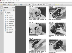
lllustration and Text
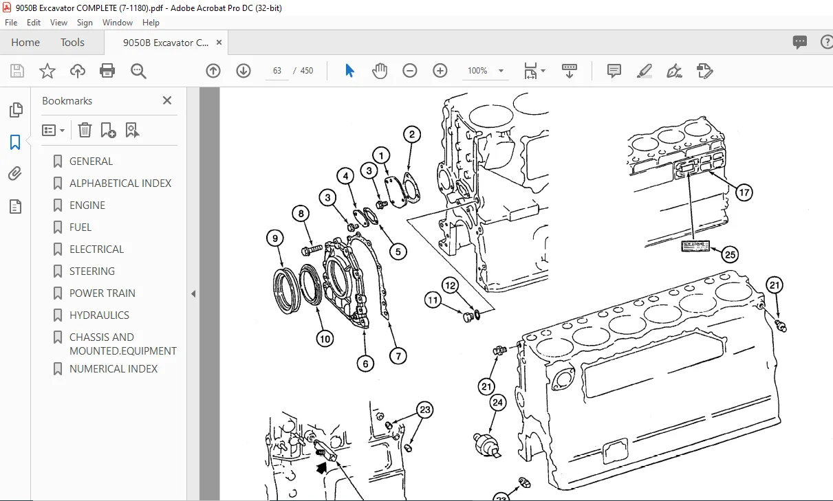
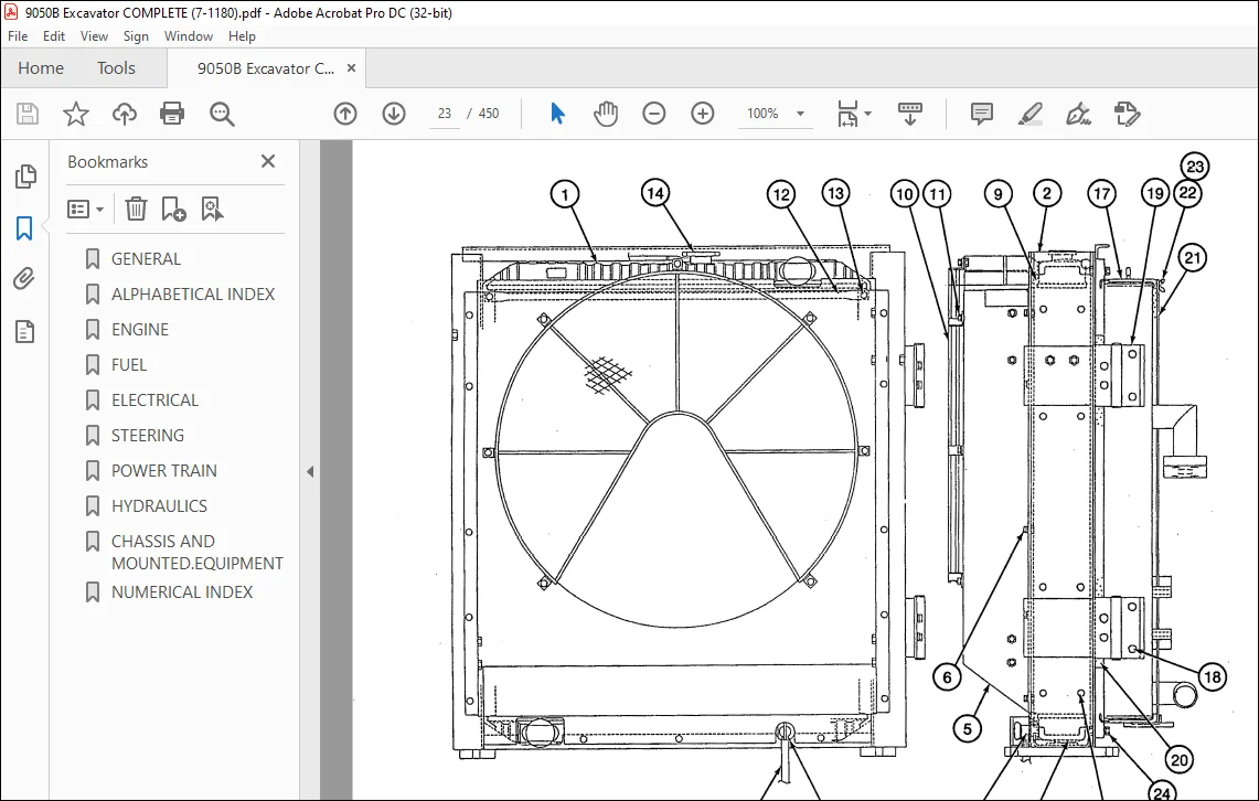
The arrangement of this parts catalog is for easy identification of parts Ali parts are iliustrated in “exploded views” in proper relation to each other. Reference numbers used in the iliustrations reter to those on the text pages. The text pages list reference number, part number, part description ahd the quantity required.
TABLE OF CONTENTS:
Case 9050B Excavator Parts Catalog Manual 7-1180 – PDF DOWNLOAD
A
Adjuster – track ……………………………………….. 5-9
Air Cleaner System ………………………………… 2-13
Air Compressor System …………………… 2-59,2-61
Air Conditioner with Heater and Hoses …….. 9-41
Air Conditioner Compressor Mounting ……… 2-21
Air Intake Heater ……………………………………. 2-25
Air Restriction Indicator Switch ………………… 2-13
Alarm – travel ………………………………………….. 4-9
Alternator and Regulator …………………………. .4-7
Alternator Mounting …………………………………. 4-3
Antenna – radio ……………………………………… 9-53
Arm
Control Lines ………………………………. 8-53,8-55
Cylinder ………………………………….. 8-157,8-159
Cylinder Lines ……………………………………. 8-59
Cylinder Supply Lines …………………………. 8-57
Arm and Bucket Supply Lines …………………. 8-57
Arm and Cylinder …………………………………… 9-75
Ashtray ………………………………………………… 9-53
Auxiliary Equipment Option
Supply and Cylinder Line Mounting. 8-115, 117
Auxiliary Hydraulic Controls …………………….. 9-49
B
Batteries, Battery Cables and Mounting ……. 4-15
Battery Cables ………………………………………. 4-15
Battery Relay ………………………………………….. 4-9
Belt – AC compressor …………………………….. 2-21
Belt – alternator ……………………………………… 2-23
Belt – fan ………………………………………………. 2-23
Belt – seat …………………………………………….. 9-35
Belt – water pump ………………………………….. 2-23
Block – cylinder ……………………………………… 2-49
Boom
Control Lines ………………………. 8-45,8-47,8-49
Cylinder ………………………………….. 8-153,8-155
Cylinder Lines ……………………………………… 8-5
Boom Lubrication Lines ………………………….. 9-71
Boom, Mounting Pins and Cylinders ………… 9-73
Bucket
Control Lines ……………………………………… 8-61
Cylinder ………………………………….. 8-161,8-163
Cylinder Lines ……………………………………. 8-65
Cylinder Supply Lines …………………………. 8-63
Buckets ……………………………………… 9-79 – 9-89
Bucket Teeth ………………………………… 9-91, 9-93
Bypass Oil Filter and Lines ……………………… 8-19
c
Cab
Air Conditioner …………………………………… 9-43
Door …………………………………………………. 9-63
c
Cab – continued
Electrical System ……………………………….. 4-19
Fan ………………………………………………….. 9-69
Floor, Mounting and Mats ……………………. 9-45
Front Window Assembly ……………………… 9-57
Lower Front Window ………………………….. 9-59
Rear Console/ Panels (w/o AC) …………… 9-65
Rear Console/Panels (w/AC) ………………. 9-67
Vandal Guards ………………………………….. 9-61
Cables – battery …………………………………….. 4-15
Cables – ground ……………………………………. 4-13
Camshaft and Timing Gears …………………… 2-47
Carrier Roller – track ………………………………. 5-11
Chain – track …………………………………………… 5-5
Cluster – instrument.. ……………………………… 4-17
Connecting Rods ………………………………….. 2-57
Console – instrument.. ……………………………. 4-19
Console Box Side Covers ………………………. 9-33
Control Component Mounting and Hose
Supports – battery compartment
………………………………………. 8-25, 8-27, 8-29
Control Component Mounting and Hose
Supports – cab …………………………………… 8-31
Control Console Linkage ………………… 9-21, 9-23
Controller – electrical system …………………… 4-19
Controller – motor driver …………………………. 4-19
Control Lines
Arm …………………………………………… 8-53,8-55
Boom ………………………………… 8-45,8-47,8-49
Bucket ……………………………………………… 8-61
Swing ………………………………………… 8-67,8-69
Travel ………………………………… 8-77,8-79,8-81
Control Panel Assemblies ………………………. 9-31
Control Signal Lines ……………………….. 8-33,8-35
Control Valve
Drain Lines ……………………………………….. 8-85
Housings and Misc Components ………… 8-127
Main Pilot Valves ……………………………… 8-129
Manually Operated …………………………… 8-121
Miscellaneous Valves and
Components ……… 8-133,8-135,8-137,8-139
Mounting …………………………………………. 8-125
Pedal operated ………………………………… 8-123
Pilot Lines ………………………………….. 8-41,8-43
Pilot Control Solenoid ……………………….. 8-141
Pressure and Return Lines ………………….. 8-25
Supply Lines ………………………………… 8-9,8-11
Working Circuit Relief Valves …………….. 8-131
Coolant Overflow Reservoir ……………………… 2-9
Cooler – engine oil. ………………………………… 2-33
Cooler – hydraulic oil ……………………………… 2-11
Bur 7-1180 Issued April, 1995 Printed in U.S.A.
1-6 90508 Excavator
ALPHABETICAL INDEX
C
Cooling System Hose Supports ……………….. 8-13
Cooling System Supply and Return Lines …. 8-15
Cooling Systems
Engine ………………………………………………. 2-11
Engine Oil …………………………………………. 2-33
Hydraulic Oil. ……………………………………… 2-11
Return Line …………………… ……….. ………… 8-15
Supply Line ……………………………………….. 8-15
Counterweight ………………………………………. 9-11
Covers – access ………………………………………. 5-3
Crankshaft ……………………………………………. 2-53
Cushion Valve …………………………………….. 8-145
Cylinder Block Assembly ………………………… 2-49
Cylinder Block Attaching Parts ………………… 2-39
Cylinder Head ……………………………………….. 2-39
Cylinder Head Covers and Engine Breather 2-43
Cylinder Lines
Arm ………………………………………………….. 8-59
Boom ………………………………………………… 8-51
Bucket ………………………………………………. 8-65
Cylinders – hydraulic
Arm ……………………………………….. 8-157,8-159
Boom ……………………………………… 8-153,8-155
Bucket ……………………………………. 8-161,8-163
D
Damper Valve ……………………………………….. 9-47
Decals ………………………………… 9-97, 9-99, 9-101
Dipstick ………………………………………………… 2-37
Dome Lamp ………………………………………….. 9-49
Door – cab …………………………………………….. 9-63
Double Action Auxiliary Equipment Option
Component Mounting and Tube
Supports ……………………………….. 8-99,8-1 01
Cylinder Supply and Relief Lines .. 8-109,8-111
Dual Flow Lines ……………………………….. 8-113
Pilot Control Lines …………………………….. 8-107
Pilot Lines – Battery Compartment ………. 8-1 03
Pilot Lines – Cab ……………………………….. 8-105
E
Electrical Components
Alternator ……………………………………………. 4-7
Battery ………………………………………………. 4-15
Instrument Cluster ………………………………. 4-17
Lamp – cab ………………………………………… 9-49
Starter ………………………………………………… 4-5
Travel Alarm ………………………………………… 4-9
Emergency Engine Stop ………………………… .4-25
Engine Components
Camshaft …………………………………………… 2-47
E
Engine Components – continued
Crankshaft …………………………………………. 2-53
Cylinder Block ……………………………………. 2-49
Cylinder Head Covers … .. …………………….. 2-43
Flywheel and Housing …………………………. 2-55
Gasket Kit .. ………………………………………… 2-51
Heater – air intake …………. ……………………. 2-25
Manifolds …………………………………………… 2-25
Oil Cooler ………………………………………….. 2-33
Oil Filler …………………………………………….. 2-37
Oil Filters …………………………………………… 2-31
Oil Pan ………………………………………………. 2-37
Oil Pump ……………………………………………. 2-35
Pistons/Connecting Rods …………………….. 2-57
Thermostats ………………………………………. 2-45
Turbocharger. ……………………………. 2-27, 2-29
Valve Mechanism ……………………………….. 2-41
Water Pump ………………………………………. 2-33
Engine Mounting and Adapting Parts …………. 2-3
Equipment Pump
Assembly ……………………. …………………… 8-119
Mounting ……………………………………………… 8-3
Exhaust Manifold …………………………………… 2-25
Exhaust System …………………………………….. 2-15
F
Fan, Fan Drive and Idler Pulley ……………….. 2-17
Fan Belt. ……………………………………………….. 2-23
Fan Lube Lines ………………. .. …………………… 2-19
Fans
Alternator … ………………………………………….. 4-7
Cab ………… ………………………………………… 9-69
Engine Cooling …………………………………… 2-17
Filler – engine oil. ……………………………………. 2-37
Filters
Air ………………………………………… ………….. 2-13
Air System …………………………………………. 8-21
Engine Oil .. …… ; ………………………………….. 2-31
Fuel, in tank …………………………………………. 3-3
Hydraulic Oil .. 8-19, 8-27,8-37,8-75,8-91,8-101
Filter and Reservoir Return Lines …………….. 8-17
Final Drive Transmission ………………………….. 6-3
Floor, Mounting and Mats …………… ………….. 9-45
Flywheel and Housing …………………………….. 2-55
Frame – track …………………………………………… 5-3
Free Swing Circuit… ……………………………….. 8-71
Free Swing Solenoid Valve ……………………. 8-143
Front Gear Cover …………………………………… 2-21
Fuel Filter ……………………………………………… 3-17
Fuel Filter and Hoses ……………………………… 3-17
Fuel Filter – in tank …………………………………… 3-3
Bur7-1180 Issued April, 1995 Printed in U.S.A.
90508 Excavator 1-7
ALPHABETICAL INDEX
F H
Fuel Injection Nozzle ……………………………… 3-15 Hydraulic Pump and Coupling ………………….. 8-5
Fuel Injection Pump and Mounting …………… 3-13 Hydraulic Reservoir …………………………………. 8-3
Fuel Injection Tubes ………………………………… 3-9 Hydraulic Swivel. …………………………………. 8-165
Fuel Level Sendor …………………………………… 3-3
Fuel Feed Pump ……………………………………. 3-13 I
Fuel Lines ………………………………………………. 3-5 Idler Wheel …………………………………………….. 5-7
Fuel Return Lines ………………………………….. 3-11 Index – numerical ………………………………….. 10-1
Fuel Tank ……………………………………………….. 3-3 I njection Nozzle – fuel. ……………………………. 3-15
Fuse Box ……………………………………………… 4-19 Injection Pump and Mounting …………………. 3-13
Fuses – electrical …………………………………….. 4-9 Instrument Cluster and Mounting …………….. 4-17
G L
Gasket Kit – engine ………………………………… 2-51 Lamps – work ……………………………………….. 4-21
Gauge – liquid level (fuel) ………………………….. 3-3 Left-hand Control Console Linkage …………. 9-29
Ground Cables ……………………………………… 4-13 Lighter – cigar ……………………………………….. 4-19
Guide – track …………………………………………… 5-3 Liners – engine cylinder. …………………………. 2-57
Lines – fuel …………………………………………….. 3-5
H Linkage for 10ft. 7 inch Arm …………………… 9-77
Harness
Controller ………………………………………….. 4-19 M
Electrical …………………………………………… 4-19 Main Electrical System Clamping ……………. 4-11
Free Swing Switch ……… …………………….. .4-19 Main Electrical Wiring ……………………………… 4-9
Main Wiring …………………………………………. 4-7 Manifolds including Air Inlet Heater …………. 2-25
Wiring ……………………………………………….. 4-19 Manual Control Valve
Wiring – left-hand controllever. ………….. .. .4-19 Pressure and Return Lines ………………….. 8-41
Wiring – right-hand control lever …………… .4-19 Manually Operated Control Valve ………….. 8-121
Head – cylinder ……………………………………… 2-39 Mirror – rear view …………………………………… 9-23
Head Gasket. ………………………………………… 2-39 Miscellaneous Drain Lines ……………………… 8-89
Heater – air intake ………………………………….. 2-25 Miscellaneous Parts – cab ………………. 9-53, 9-55
Heater and Hoses – cab ………………………….. 9-39 Motor – track drive …………………….. 6-3,6-9, 6-11
Horns …………………………………………………….. 4-9 Motor – wiper ………………………………………… 9-57
Hose Supports …………. 8-13,8-25,8-27,8-29,8-31 Mounting
Hoses – radiator ………………………………………. 2-5 Engine ……………………………………………….. 2-3
Hydraulic Circuits Main Control Valve …………………………… 8-125
Arm Circuit ………………………………. 8-53 – 8-59 Radiator ……………………………………………… 2-7
Boom Circuit ……………………………. 8-45 – 8-51 Swing Drive Assembly ………………………. 8-167
Bucket Circuit.. …………………………. 8-61 – 8-65 Muffler – engine exhaust ………………………… 2-15
Pressure and Return Circuits ………… 8-41 ,8-43 Muffler and Exhaust System …………………… 2-15
Swing Circuit ……………………………. 8-67 – 8-75
Travel Circuit.. ………………………….. 8-77 – 8-83 N
Hydraulic Control Valve …………….. 8-125 – 8-139 Nozzle – fuel injection …………………………….. 3-15
Housing and Miscellaneous Numerical Index ……………………………………. 10-1
Components …………………………………. 8-127
Main Pilot Valves ……………………………… 8-129 o
Miscellaneous Valves and Components Oil Cooler – engine oil ……………………………. 2-33
…………………………………………… 8-133 – 8-137 Oil Cooler – hydraulic oi!. ………………………… 2-11
Mounting …………………………………………. 8-125 Oil Cooler – return line ……………………………. 8-17
Working Circuit Relief Valves ……………… 8-131 Oil Cooler – supply line …………………………… 8-15
Hydraulic Oil Cooler. ………………………………. 2-11 Oil Filler ……………………………………………….. 2-37
Hydraulic Oil Pumps …………………………….. 8-119 Oil Filter – hyd ….. 8-19,8-27,8-37,8-75,8-91,8-101
Hydraulic Pump Assembly …………………….. 8-119 Oil Filters – engine …………………………………. 2-31
Oil Lines ………………………………………………. 2-63
o
Oil Pan …………………………………………………. 2-37
Oil Pump and Strainer ……………………………. 2-35
Operator’s Manual Tether ……………………….. 9-35
p
Pan – oil ……………………………………………….. 2-37
Panel – instrument, side …………………………. .4-19
Pedal and Floor Mat – aux. hyd. controls …… 9-49
Pedal Control Valve –
Pressure and Return Lines ………………….. 8-43
Pedal Operated Control Valve ……………….. 8-123
Pedals and Levers – track drive control …….. 9-47
Pilot Component Mounting and Hose
Supports …………………………………… 8-25 – 8-31
Pilot Control Lines
Double Action Auxiliary Equipment
Option ………………………………………….. 8-107
Single Action Auxiliary Equipment
Option ……………………………………………. 8-93
Pilot Control Solenoid Valve ……………. 8-141
Pilot Lines
Hydraulic Pump and Filter ……………………. 8-37
Miscellaneous ……………………………………. 8-39
Pilot Pressure Distribution Lines ………………. 8-39
Pistons and Connecting Rods …………………. 2-57
Pressure and Return Lines-control valve 8-41,43
Pressure and Return Manifold Drain Lines … 8-87
Pulley
AlC Compressor ………………………………… 2-21
Alternator ……………………………………………. 4-7
Crankshaft. ………………………………………… 2-53
Fan and Water Pump ………………………….. 2-23
Pump
Engine Oil …………………………………………. 2-35
Fuel Feed ………………………………………….. 3-13
Fuel Injection ……………………………………… 3-13
Hydraulic OiL ……………………………………. 8-119
Pilot Supply Lines ………………………………. 8-37
Water ……………………………………………….. 2-23
Pump and Drive – injection ……………………… 3-13
Pump and Filter – pilot lines …………………….. 8-37
R
Radiator – engine …………………………………… 2-11
Radiator and Hoses …………………………………. 2-5
Radiator Assembly ………………………………… 2-11
Radiator Mounting, Supports and Seals ……… 2-7
Radiator Overflow Reservoir and Hoses …….. 2-9
Radiator Supports …………………………………… :2-7
Radio …………………………………………………… 4-19
Rear Console and Panels – cab ……….. 9-65, 9-67
Rear View Mirror. …………………………………… 9-23
R
Reducing Valve ……………………………………. 8-151
Reduction Gear Assembly …………………….. 8-173
Relay
Alternator Safety … …………………. ……………. .4-9
Battery ………………………………………………… 4-9
Electrical System Controller ………………… .4-19
Intake Air Heater …………………………………. .4-9
Starter …………………………………………………. 4-9
Remote Control Valve
Assemblies ……….. 8-121 ,8-123,9-25,9-47,9-49
Reservoir – hydraulic oil ……………………………. 8-3
Reservoir – pressurization system …….. 8-21,8-23
Reservoir – radiator overflow ……………………… 2-9
Reservoir to Pump Suction Line ………………… 8-7
Return Lines – filter and reservoir. …….. 8-17,8-19
Right-Hand Control Console Linkage ……….. 9-27
Roller – carrier ……………………………………….. 5-11
Roller – track ………………………………………….. 5-13
Roof Panel Assembly ……………………………… 9-59
S
Seat. … …………………. ………………………………. 9-35
Seat Belt ………………………………………………. 9-35
Seat Slide Rails and Platform ………………….. 9-35
Senders
Air Filter Restriction ………………………………. 2-7
Bypass oil pressure …………………………….. 2-51
Fuel Level ……………………………………………. 3-3
Sensor
low electrolyte level ……………………………. .4-15
temperature …………………………………………. 4-9
Separator – water …………………………………….. 3-5
Shoe – track ………….. ………………………………… 5-5
Single Action Auxiliary Equipment Option
Component Mounting And Tubing Supports
………………………………………………………… 8-91
Cylinder Supply and Relief Lines ….. 8-95,8-97
Pilot Control Lines ………………………………. 8-93
Solenoid Valve ………………….. 8-141 ,8-143,8-149
Solenoid Valve Pilot Lines …………………….. 8-141
Solenoid Valves
Free Swing ………………………………………. 8-143
Pilot Control ……………………………………… 8-141
Selector Valve – Aux. Option ………………. 8-149
Solenoid – engine starter. …………………………. .4-5
Solenoid – engine stop …………………………… .4-25
Sprocket – track drive ………………………… 5-3, 6-3
Starter – engine ………………………………………. .4-5
Starter – mounting …………………………………… .4-3
Starter – solenoid …………………………………….. .4-5
Steering – power circuit ………………………. 5-5,5-7
Steering Control Valve ……………………………. 5-11
Bur 7-1180 Issued April, 1995 Printed in U.S.A.
90508 Excavator 1-9
ALPHABETICAL INDEX
S T
Suction Line – reservoir to pump ………………… 8-7 Turntable – continued
Supply and Return Lines – hydraulic oil cooling Bearing … ……………………………………………. 9-3
system ………………………………………….. 8-15,8-17 Bearing Lubrication Lines ……………………… 9-5
Supply Hydraulic Circuit ……………………. 8-9,8-11 Turntable and Walkways …….. …….. ……………. 9-7
Supply Lines – arm …………. ……………………… 8-57
Supply Lines – bucket …………………………….. 8-63 u
Supply Lines – control valve ……………….. 8-9,8-11 Upper Structure
Swing Brake Release Valve ………………….. 8-147 Frames, Covers and Insulation …….. 9-13,9-15
Swing Control Lines ……….. ………… ……. S-67,S-69 Hoods, Covers and Insulation ………. 9-17,9-19
Swing Motor Assembly ………………… 8-169,8-171 Left-Hand and Right-Hand Side Doors ….. 9-21
Swing Motor Power Circuit ……………………… 8-73 Rear View Mirror ……………….. ……………… 9-23
Swing System Storage Box ………………………………………. 9-23
Brake Release Valve ………………………… 8-147
Control Lines ………………………………. 8-67,8-69 V
Drive Assembly Mounting ………………….. 8-167 Valve – damper. …………………………………….. 9-47
Motor Assembly ………………………. 8-169,8-171 Valves – hydraulic
Motor Power Circuit ……………………………. 8-73 Control ……………………………………………. 8-121
Reduction Gear Assembly …………………. 8-173 Cushion ………….. ……………………………… 8-145
Switches Free Swing Solenoid ………………………… 8-143
Air Restriction Indicator ………… .. …………… 2-13 Manually Operated Control ……………….. 8-121
Auxiliary Attachment Control. ………………. .4-19 Pedal Operated Control. ……………………. 8-123
Ignition ……………………………………. ……. …. 4-19 Pilot Control Solenoid …………………. ……. 8-141
Key …………………………………………………… 4-19 Swing Brake Release ……………………….. 8-147
Lamps – work …………………………………….. 4-21 Solenoid – aux. option ……………………….. 8-149
Oil Pressure, bypass … … ……….. … …………. 2-31 Valve – solenoid ……………………………… 4-7,4-23
Pressure ……………………………………………… 4-9 Valve Assembly – remote
Starter ………………………………………………. 4-19 contro!.. ……………………… ………….. 8-121,8-123
Temperature ……………………………………….. 4-9 Valve Mechanism .. ……….. ………………………. 2-41
Travel Speed SelecL …………………………. .4-19
Swivel ………………………………………………… 8-165 w
Swivel and Swing Motor Drain Lines ………… 8-75
Water Pipe and Thermostats ………………….. 2-45
T Water Pump Assembly and Belts ……………. 2-23
Tank – fuel ………………………………………………. 3-3 Windows and Seals – cab ………………………. 9-51
Tank – oil, hydraulic ………………………………… 8-3 Windshield Washer ………. ………………………. 4-23
Thermostats ………………………………………….. 2-45 Windshield and Wiper ……………………………. 9-57
Throttle and Fuel Shutoff Controls ……………… 3-7 Work Lamps and Wiring … ………………………. 4-21
Throttle Control Motor. ……………………………… 3-7
Tools ……………………………………………………. 9-95
Track Adjuster ………………………………………… 5-9
Track Chain ……………………………………………. 5-5
Track Drive Controls ………………………………. 9-47
Track Drive Hydraulic Circuit …………………… 8-83
Swivel to Track Drive Motors ……………….. 6-13
Track Drive Motor …………………….. 6-3, 6-9, 6-11
Track Frame and Drive Sprocket… …………….. 5-3
Transmission Assembly ………………… 6-3,6-5,6-7
Travel Alarm ………………… ……….. ……. ………… 4-9
Travel Control Lines ……… ……….. 8-77,8-79,8-81
Turbocharger ………………………………… 2-27, 2-29
Turntable ……………. …………………………………. 9-5
Access Covers ………………………………. 9-3,9-9
IMAGES PREVIEW OF THE MANUAL:
CASE 9050B EXCAVATOR PARTS CATALOG MANUAL 7-1180 – PDF DOWNLOAD:
PLEASE NOTE:
- This is not a physical manual but a digital manual – meaning no physical copy will be couriered to you. The manual can be yours in the next 2 mins as once you make the payment, you will be directed to the download page IMMEDIATELY.
- This is the same manual used by the dealers inorder to diagnose your vehicle of its faults.
- Require some other service manual or have any queries: please WRITE to us at [email protected]
S.V