Case 9050B Excavator Parts Catalog Manual 7-2391 – PDF DOWNLOAD
Original price was: $89.95.$31.95Current price is: $31.95.
Case 9050B Excavator Parts Catalog Manual 7-2391 – PDF DOWNLOAD
Description
Case 9050B Excavator Parts Catalog Manual 7-2391 – PDF DOWNLOAD
DESCRIPTION:
Case 9050B Excavator Parts Catalog Manual 7-2391 – PDF DOWNLOAD
GENERAL INFORMATION
Indexes
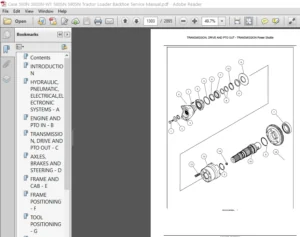
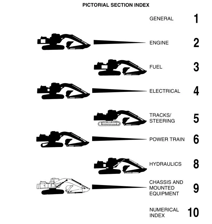
Section 1 of this catalog contains a SN and PI N. location guide, alphabetical index, pictorial index of the sections included, and pictorial index(es) for quick location of hases and tubes (and other system components in some catalogs) An alphabetical index siso appears at the beginning of each section Section 10 is the Numerical lndex which lists ali part numbers in alpha/numeric arder with their page location and reference number.
lllustration and Text
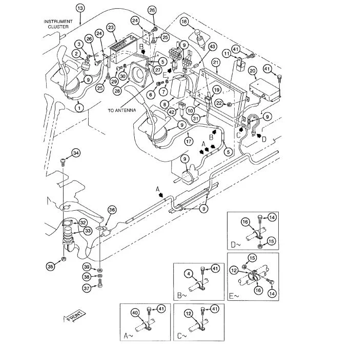
The arrangement of this parts catalog is for easy identification of parts Ali parts are iliustrated in “exploded views” in proper relation to each other. Reference numbers used in the iliustrations reter to those on the text pages. The text pages list reference number, part number, part description ahd the quantity required.
TABLE OF CONTENTS:
Case 9050B Excavator Parts Catalog Manual 7-2391 – PDF DOWNLOAD
A
Adjuster – track ………………………………. 5-15,5-17
Air Cleaner System …………………………. 2-11,2-13
Air Conditioner ………………. 4-25,9-63 – 9-71,9-99
Air Restriction Indicator Switch …………… 2-11,4-5
Alarm – travel ………………………………………….. 4-9
Alternator Relay …………………………….. .4-13,4-15
Antenna – radio ……………………………………… 9-83
Antid rift Valve ……………………………………… 8-165
Arm
Control Lines ………………………………. 8-57,8-59
Cylinder …………………………………………… 8-191
Cylinder Lines …………………………….. 8-65,8-67
Cylinder Supply Lines ………………….. 8-61,8-63
Arm and Cylinder
2.63M (8 ft 8 in) & 3.23M (10 ft 7 in) ……. 9-113
4.03M (13 ft 3 in) ………………………………. 9-115
Ashtray ………………………………………………… 9-83
Auxiliary Equipment Option
Supply and Cylinder Line
Mounting ……………………………. 8-129 – 8-135
Auxiliary Hydraulic Controls …………………….. 9-79
B
Batteries, Battery Cables and Mounting ……. 4-11
Battery Cables …………………………… .4-3,4-7,4-11
Battery Relay ………………………………… .4-13,4-15
Belt – seat ……………………………………… 9-49,9-53
Boom
Control Lines ………………………………. 8-49,8-51
Cylinder …………………………………………… 8-189
Cylinder Lines ……………………………………. 8-55
Pilot Lines …………………………………………. 8-53
Boom Lubrication Lines ……………….. 9-107,9-109
Boom, Mounting Pins and Cylinders ………. 9-111
Bucket
Control Lines ……………………………………… 8-69
Cylinder ………………………………….. 8-193,8-195
Cylinder Lines …………………………… 8-75 – 8-79
Cylinder Supply Lines ………………….. 8-71,8-73
Buckets …………………………………… 9-119 – 9-133
Bucket Teeth ……………………………… 9-135,9-137
Bypass Oil Filter and Lines ……………………… 8-19
C
Cab
Air Conditioner ……………………. 9-63-9-71,9-99
Door …………………………………………………. 9-93
Electrical System ……………………………….. 4-19
Fan ………………………………………… 9-101,9-103
Floor, Mounting and Mats ……………………. 9-73
Front Window Assembly ……………………… 9-87
Lower Front Window …………………………… 9-89
Bur 7-2391
C
Cab – continued
Miscellaneous Parts ……………………. 9-83,9-85
Rear Console/ Panels (w/o AC) ……………. 9-95
Rear Console/Panels (w/AC) ……………….. 9-97
Roof Panel Assembly ………………………….. 9-89
Vandal Guards …………………………………… 9-91
Windows and Seals …………………………….. 9-81
Cables – battery ………………………….. 4-3,4-7,4-11
Cables – ground ………………………………………. 4-9
Carrier Roller – track ……………………….. 5-19,5-21
Chain – track ……………………………………… 5-7,5-9
Cluster – instrument… …………………………….. .4-17
Cold Start ……………………………………………… 2-15
Console – instrument… ……………………. 4-17,4-19
Console Box Control Panel Assemblies ……. 9-47
Control Component Mounting and Hose
Supports…………………………………. 8-29 – 8-33
Control Component Mounting and Hose
Supports – cab ……………………………………. 8-35
Controller – electrical system …………………… .4-19
Controller – motor driver …………………………. .4-19
Control Lines
Arm …………………………………………… 8-57,8-59
Boom ……………………………………….. 8-49,8-51
Bucket ………………………………………………. 8-69
Swing ………………………………………… 8-81,8-83
Travel ……………………………………… 8-91 – 8-95
Control Panel Assemblies ……………………….. 9-47
Control Signal Lines ……………………….. 8-37,8-39
Control Valve
Drain Lines ………………………………………. 8-109
Housings and Miscellaneous
Components …………………………………. 8-161
Main Pilot Valves ………………………………. 8-163
Manually Operated ……………………………. 8-153
Miscellaneous Valves and
Components ……………………… 8-167 – 8-175
Mounting ………………………………………….. 8-159
Pedal Operated ………………………. 8-155,8-157
Pilot Lines ………………………………………….. 8-43
Pilot Control Solenoid ………………………… 8-177
Supply Lines ………………………………. 8-13,8-15
Working Circuit Relief Valves ……. 8-165,8-167
Coolant Overflow Reservoir ………………………. 2-9
Cooling System Hose Supports ……………….. 8-17
Cooling System Supply and Return Lines …. 8-17
Cooling Systems
Engine ………………………………………….. 2-5,2-7
Return Line ………………………………………… 8-17
Supply Line ………………………………………… 8-17
Counterweight ……………………………………….. 9-13
Covers – access ………………………………… 5-3,5-5
Issued December, 1999
1-6 90508 Excavator
ALPHABETICAL INDEX
C
Cushion Valve …………………………………….. 8-181
Cylinder Lines
Arm ……………………………………………… 8-65,8-67
Boom …………………………………………………… 8-55
Bucket ………………………………………… 8-75 – 8-79
Cylinders – hydraulic
Arm …………………………………………………… 8-191
Boom …………………………………………………. 8-189
Bucket ………………………………………. 8-193,8-195
D
Damper Valve …………………………………………… 9-77
Decals ………………………………………… 9-141 – 9-149
Dome Lamp ……………………………………………… 9-83
Door – cab ………………………………………………… 9-93
Double Action Auxiliary Equipment Option
Component Mounting and Tube
Supports ………………………………………….. 8-119
Cylinder Supply and Relief Lines ….. 8-125,8-127
Pilot Control Lines ………………………………… 8-123
Pilot Lines – cab …………………………………… 8-121
E
Electrical Components
Battery ………………………………………………….. 4-11
Instrument Cluster. ………………………………… .4-17
Lamp – cab, dome ………………………………….. 9-83
Travel Alarm ……………………………………………. 4-9
Engine Assembly – See Cummins Dealer
Engine Mounting and Adapting Parts ………. 2-5,2-7
Exhaust System ………………………………………….. 2-3
F
Fans
Cab ………………………………………….. 9-101,9-103
Engine Cooling ……………………………………….. 2-3
Filters
Air. ……………………………………………….. 2-11,2-13
Air System ……………………………………………. 8-19
Fuel, in tank …………………………………………… 3-3
Fuel, side of engine …………………………………. 2-3
Hydraulic Oil. …………. 8-3,8-31,8-89,8-111,8-119
Filter and Reservoir Return Lines ……………….. 8-17
Final Drive Transmission …….. 6-3 – 6-7,6-13 – 6-17
Floor, Mounting and Mats ………………………….. 9-73
Frame – track ………………………………………… 5-3,5-5
Free Swing Circuit …………………………………….. 8-85
Free Swing Solenoid Valve ………………………. 8-179
Fuel Filter – in tank ………………………………………. 3-3
Fuel Level Sender ………………………………………. 3-3
Fuel Lines ………………………………………………….. 3-5
Fuel Tank …………………………………………………… 3-3
Bur 7-2391
F
Fuse Box ………………………………………………. 4-19
Fuses – electrical. …………………………… 4-13,4-15
G
Gauge – liquid level (fuel) ………………………….. 3-3
Gauge – oil ……………………………………………… 8-3
Ground Cables ………………………………………… 4-9
Guards – vandal …………………………………….. 9-91
Guide – track …………………………………………… 5-3
H
Harness
Controller. ………………………………………….. 4-19
Electrical ……………………………………. 4-13,4-15
Extensions …………………………………………. 4-27
Free Swing Switch …………………………….. .4-19
Wiring ……………………………………………….. 4-19
Wiring – left-hand control lever …………….. .4-19
Wiring – right-hand control lever …………… .4-19
Heater and Hoses – cab ………………… 9-59 – 9-63
Horns ………………………………………………. 4-3,4-5
Hose Supports ……………………… 8-17,8-28 – 8-35
Hoses – radiator ………………………………… 2-5,2-7
Hydraulic Circuits
Arm Circuit ………………………………. 8-57 – 8-67
Boom Circuit… ………………………….. 8-49 – 8-59
Bucket Circuit …………………………… 8-69 – 8-79
Load Hold …………………………….. 8-217 – 8-229
Pressure and Return Circuits ……….. 8-45,8-47
Swing Circuit ……………………………. 8-81 – 8-89
Track Drive ……………………….. 6-25,6-27,8-103
Travel Circuit.. ………………………… 8-91 – 8-101
Hydraulic Control Valve …………….. 8-159 – 8-175
Housing and Miscellaneous
Components …………………………………. 8-161
Main Pilot Valves ………………………………. 8-163
Miscellaneous Valves
and Components ……………….. 8-169 – 8-175
Mounting …………………………………………. 8-159
Working Circuit Relief Valves ……. 8-165,8-167
Hydraulic Pump Assembly …………. 8-137 – 8-151
Hydraulic Pump and Coupling …………………… 8-5
Hydraulic Reservoir …………………………………. 8-3
Hydraulic Swivel ………………………………….. 8-197
I
Idler Wheel. …………………………………… 5-11 ,5-13
Index – numerical …………………………………… 10-1
Instrument Cluster and Mounting ……………… 4-17
K
Key – ignition switch ……………………………….. 4-19
1-7
L
Lamps – work ………………………………….. .4-5,4-21
Left-Hand Control Console Linkage ….. 9-43,9-45
Lighter – cigar. ……………………………………….. 4-19
Lines – fuel ……………………………………………… 3-5
Linkage Arms ………………………………………. 9-117
M
Main Electrical Wiring …………………….. .4-3 – 4-15
Manual Control Valve
Pressure and Return Lines ………………….. 8-45
Manually Operated Control Valve …………… 8-153
Miscellaneous Drain Lines ………….. 8-105 – 8-109
Miscellaneous Parts – cab ……………….. 9-83,9-85
Motor – throttle control ……………………………… 3-7
Motor – track drive …. 6-3,6-9,6-11,6-13,6-19,6-23
Motor – wiper. ………………………………………… 9-87
Mounting
Control Component.. ………………….. 8-29 – 8-33
Double Action Auxiliary Equipment.. ……. 8-119
Engine ………………………………………………… 2-3
Main Control Valve ……………………………. 8-159
Radiator ………………………………………… 2-5,2-7
Single Action Auxiliary Equipment ………. 8-111
Swing Drive Assembly ……………… 8-199,8-201
Muffler – engine exhaust …………………………… 2-3
N
Numerical Index …………………………………….. 10-1
0
Oil Cooler- return line ……………………………. 8-17
Oil Cooler – supply line …………………………… 8-17
Oil Filter
Hydraulic ……………. 8-3,8-31,8-89,8-111,8-119
Operator’s Manual Tether. ………………………. 9-49
p
Panel – instrument, side ………………………….. 4-17
Pedal and Floor Mat
Auxiliary Hydraulic Controls …………………. 9-79
Pedal Control Valve –
Pressure and Return Lines ………………….. 8-47
Pedal Operated Control Valve …….. 8-153 – 8-157
Pedals and Levers – track drive control 9-75,9-77
Pilot Control Lines
Double Action Auxiliary Equipment
Option ………………………………………….. 8-123
Single Action Auxiliary Equipment
Option ………………………………………….. 8-113
Pilot Control Solenoid Valve ……………. 8-177
Bur 7-2391
p
Pilot Lines
Boom ………………………………………………… 8-53
Hydraulic Pump and Filter ……………………. 8-41
Miscellaneous …………………………………….. 8-43
Pilot Pressure Distribution Lines ………………. 8-43
Pressure and Return Lines
Control Valve ……………………………… 8-45,8-47
Pressure and Return Manifold Drain Lines .8-107
Pump
Auxiliary …………………………………………….. 8-11
Hydraulic Oil. ………………………… 8-137 – 8-151
Pilot Supply Lines ……………………………….. 8-41
Pump and Filter – pilot lines …………………….. 8-41
R
Radiator and Hoses …………………………… 2-5,2-7
Radiator Mounting, Supports and Seals .. 2-5,2-7
Radiator Overflow Reservoir and Hoses ……… 2-9
Radiator Supports ……………………………… 2-5,2-7
Radio ……………………………………………………. 4-19
Radio Speakers …………………………………….. 4-19
Rear Console and Panels – cab ……….. 9-95,9-97
Reducing Valve ……………………………………. 8-187
Reduction Gear Assembly …………… 8-211,8-213
Relay
Alternator Safety …………………………. 4-13,4-15
Battery ………………………………………. 4-13,4-15
Box …………………………………………………… 4-13
Electrical System Controller ………………… .4-19
Starter ……………………………………….. 4-13,4-15
Remote Control Valve
Assemblies ….. 8-153 – 8-157,9-37,9-75 – ,9-79
Reservoir – hydraulic oil ……………………………. 8-3
Reservoir – pressurization system …….. 8-21,8-23
Reservoir – radiator overflow ……………………… 2-9
Reservoir – washer fluid ………………………….. 4-23
Reservoir to Pump Suction Line ………….. 8-7,8-9
Return Lines – filter and reservoir ……… 8-17,8-19
Right-Hand Control Console
Linkage ……………………………………… 9-39,9-41
Roller – carrier ……………………………….. 5-19,5-21
Roller – track ………………………………….. 5-23,5-25
Roof Panel Assembly ……………………………… 9-89
s
Seat. …………………………………………… 9-49 – 9-53
Seat Belt ………………………………………. 9-49,9-53
Seat Slide Rails and Platform ………….. 9-55,9-57
Senders
Fuel Level ……………………………………………. 3-3
Issued December, 1999
1-8 90508 Excavator
ALPHABETICAL INDEX
s
Sensor
Low Electrolyte Level ………………………….. 4-11
Tachometer …………………………………………. 2-3
Temperature ……………………………………….. 4-9
Shoe – track ………………………………………. 5-7,5-9
Single Action Auxiliary Equipment Option
Component Mounting And Tubing
Supports ………………………………………. 8-111
Cylinder Supply and Relief Lines .. 8-115,8-117
Pilot Control Lines …………………………….. 8-113
Solenoid Valve …………………… 8-177 ,8-179 ,8-185
Solenoid Valves
Free Swing ………………………………………. 8-179
Pilot Control …………………………………….. 8-177
Selector Valve – auxiliary option ………….. 8-185
Speaker – radio ……………………………………… 4-19
Sprocket – track drive …………….. 5-3,5-5,6-3,6-13
Starter – relay ………………………………… .4-13,4-15
Suction Line – reservoir to pump …………… 8-7,8-9
Supply and Return Lines – hydraulic oil
cooling system …………………………………… 8-17
Supply Hydraulic Circuit ………………….. 8-13,8-15
Supply Lines
Arm …………………………………………… 8-61,8-63
Bucket ……………………………………….. 8-71,8-73
Control Valve ……………………………… 8-13,8-15
Pump Pilot. ………………………………………… 8-41
Swing Brake Release Valve ………………….. 8-183
Swing Control Lines ………………………. 8-81 – 8-89
Swing Motor Assembly ………………. 8-203 – 8-209
Swing Motor Power Circuit ……………………… 8-87
Swing System
Brake Release Valve ………………………… 8-183
Control Lines ………………………………. 8-81,8-83
Drive Assembly Mounting …………. 8-199,8-201
Motor Assembly …………………….. 8-203 – 8-209
Motor Power Circuit ……………………………. 8-87
Reduction Gear Assembly ………… 8-211 ,8-213
Switches
Air Restriction lndicator ………………….. 2-11,4-5
Auxiliary Attachment Control. ……………….. 4-19
Cold Start ………………………………………….. 4-19
Ignition ……………………………………………… 4-19
Key …………………………………………………… 4-19
Oil Pressure ………………………………………… 2-3
Pilot ……………………………………………………. 4-5
Pressure …………………………………… 4-3,4-9,8-3
Starter ………………………………………………. 4-19
Temperature ………………………………….. 2-3,4-9
Travel Speed Select… …………………………. 4-19
Swivel ………………………………………………… 8-197
Bur 7-2391
s
Swivel and Swing Motor Drain Lines ………… 8-89
T
Tank – fuel ………………………………………………. 3-3
Tank – oil, hydraulic …………………………………. 8-3
Throttle and Fuel Shutoff Controls ……………… 3-7
Throttle Control Motor ………………………………. 3-7
Tools ………………………………………………….. 9-139
Track Adjuster. ………………………………. 5-15,5-17
Track Carrier Rollers ………………………. 5-19,5-21
Track Chain ……………………………………… 5-7,5-9
Track Drive Controls ………………………. 9-75,9-77
Track Drive Hydraulic Circuit …………………. 8-103
Swivel to Track Drive Motors ……….. 6-25,6-27
Track Drive Motor …. 6-3,6-9,6-11,6-13,6-19,6-23
Track Frame and Drive Sprocket.. ……….. 5-3,5-5
Track Guide ……………………………………………. 5-3
Track Rollers …………………………………. 5-23,5-25
Track Shoes ……………………………………… 5-7,5-9
Transmission Assembly ……. 6-3 – 6-7,6-13 – 6-17
Travel Alarm …………………………………………… 4-9
Travel Control Lines ……………………. 8-91 – 8-101
Turntable ………………………………………………… 9-9
Access Covers ……………………….. 9-3,9-5,9-11
Bearing …………………………………………. 9-3,9-5
Bearing Lubrication Lines ………………………. 9-7
Turntable and Walkways ………………………….. 9-9
u
Upper Structure
Frames, Covers and Insulation …….. 9-15,9-17
Covers and Insulation ………….. 9-19,9-21,9-29
Left-Hand & Right-Hand
Side Doors…………………………….. 9-33,9-35
V
Valve – damper ……………………………………… 9-77
Valves – hydraulic
Ant id rift ……………………………………………. 8-163
Arm Cylinder Holding ………………………… 8-227
Boom Cylinder Holding ……………………… 8-229
Control – Main ……………………….. 8-159 – 8-175
Cushion …………………………………………… 8-181
Free Swing Solenoid …………………………. 8-179
Manually Operated Control ………………… 8-153
Pedal Operated Control …………… 8-155,8-157
Pilot Control Solenoid ………………………… 8-177
Reducing …………………………………………. 8-187
Shuttle …………………………………………….. 8-215
Solenoid – auxiliary option ………………….. 8-185
Swing Brake Release ………………………… 8-183
Valve Assembly – remote control … 8-153 – 8-157
Issued December, 1999
90508 Excavator
ALPHABETICAL INDEX
V
Vandal Guards ………………………………………. 9-91
w
Wheel – idler ………………………………….. 5-11,5-13
Windows
Door – upper ………………………………………. 9-93
Front. ………………………………………………… 9-87
Lower Front ……………………………………….. 9-89
Windows and Seals – cab ……………………….. 9-81
Windshield Washer ………………………………… 4-23
Windshield and Wiper. ……………………………. 9-87
Work Lamps and Wiring …………………… .4-5,4-21
IMAGES PREVIEW OF THE MANUAL:
CASE 9050B EXCAVATOR PARTS CATALOG MANUAL 7-2391 – PDF DOWNLOAD:
PLEASE NOTE:
- This is the same manual used by the dealers to diagnose and troubleshoot your vehicle
- You will be directed to the download page as soon as the purchase is completed. The whole payment and downloading process will take anywhere between 2-5 minutes
- Need any other service / repair / parts manual, please feel free to contact [email protected] . We still have 50,000 manuals unlisted
S.V