Case 988 “Plus” Wheeled Excavator Operator’s Manual 6-23520 GB – PDF DOWNLOAD
Original price was: $89.95.$29.95Current price is: $29.95.
Case 988 “Plus” Wheeled Excavator Operator’s Manual 6-23520 GB – PDF DOWNLOAD
Description
Case 988 “Plus” Wheeled Excavator Operator’s Manual 6-23520 GB – PDF DOWNLOAD
DESCRIPTION:
Case 988 “Plus” Wheeled Excavator Operator’s Manual 6-23520 GB – PDF DOWNLOAD
TO THE OWNER :
Your machine has been designed and built to the highest standards of quality. It conforms to all current safety regulations. See “Official documents”. However, the risk of accidents can never be completely excluded. That is why it is essential to observe elementary safety rules and precautions.
- Read this manual carefully, paying particular attention to the instructions concerning safety, operation and maintenance so as to avoid the risk of injury while operating or servicing the machine. Use this manual as a guide. Your machine will remain a reliable working tool provided it is kept in good working condition and serviced properly.
- The standard attachments and equipment available for use with this machine are intended for general earthmoving purposes, material rehandling, boring, ditch cleaning, etc. If the machine is to be used for handling loads, (tubing, concrete pipe sections, shoring material, etc.), make sure the machine is suitably equipped for this type of work.
- For this type of application, the machine must be equipped with safety valves, an overload indicator, a load handling chart corresponding to the type of machine and its attachment and a load fixing point.
- All legal requirements must also be strictly observed. Do not use this machine for any application or purpose other than those described in this manual. If the machine is to be used for work involving the use of special attachments, accessories or equipment, consult your CASE Dealer in order to make sure that any adaptations or modifications made are in keeping with the machine’s technical specifications and with prevailing safety requirements.
- Any modification or adaptation which is not approved by the manufacturer may invalidate the machine’s initial conformity with safety requirements. The machine must undergo regular inspections, the frequency of which varies according to the type of use. Consult your CASE Dealer.
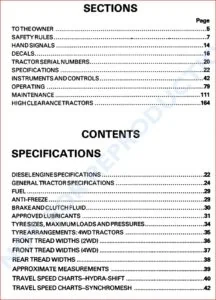
TABLE OF CONTENTS:
Case 988 “Plus” Wheeled Excavator Operator’s Manual 6-23520 GB – PDF DOWNLOAD
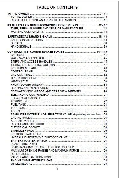
TO THE OWNER ………………………………………………………………………………. 7 – 11
TO THE OWNER ………………………………………………………………………………… 8
RIGHT, LEFT, FRONT AND REAR OF THE MACHINE …………………………. 11
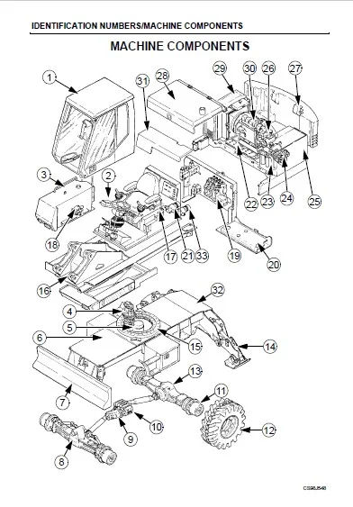
IDENTIFICATION NUMBERS/MACHINE COMPONENTS ……………………. 12 – 17
TYPE, SERIAL NUMBER AND YEAR OF MANUFACTURE …………………… 12
MACHINE COMPONENTS …………………………………………………………………. 16
SAFETY/DECALS/HAND SIGNALS ………………………………………………….. 18 – 43
SAFETY INSTRUCTIONS …………………………………………………………………. 18
DECALS …………………………………………………………………………………………… 30
HAND SIGNALS ……………………………………………………………………………….. 39
CONTROLS/INSTRUMENTS/ACCESSORIES …………………………………. 44 – 115
CAB DOOR ………………………………………………………………………………………. 44
WALKWAY ACCESS GATE ……………………………………………………………….. 45
STEPS AND ACCESS HANDLES ……………………………………………………….. 45
TILTING THE STEERING COLUMN ……………………………………………………. 47
INSTRUMENT PANEL ……………………………………………………………………….. 48
CONTROL PANEL …………………………………………………………………………….. 60
CAB CONTROLS ………………………………………………………………………………. 62
OPERATOR’S SEAT …………………………………………………………………………. 83
WINDSHIELD …………………………………………………………………………………… 86
FRONT LOWER WINDOW …………………………………………………………………. 88
HEATING AND VENTILATION ……………………………………………………………. 89
FORWARD VIEW MIRROR AND REAR VIEW MIRRORS ……………………… 90
ELECTRONIC CONTROL BOX …………………………………………………………… 91
ELECTRICAL CABINET …………………………………………………………………….. 91
TOWING EYE …………………………………………………………………………………… 92
FUEL TANK ……………………………………………………………………………………… 93
TOOL BOXES …………………………………………………………………………………… 94
TOOLS …………………………………………………………………………………………….. 94
STABILIZER/DOZER BLADE SELECTOR VALVE (depending on version) . 95
ENGINE HOODS ………………………………………………………………………………. 96
ACCESS PANELS …………………………………………………………………………….. 97
RIGHT-HAND SIDE DOOR ………………………………………………………………… 99
ELECTRICAL SOCKET ……………………………………………………………………. 100
STABILIZER PADS ………………………………………………………………………….. 100
FOLDING STABILIZERS ………………………………………………………………….. 102
HYDRAULIC RESERVOIR SHUT-OFF VALVE …………………………………… 103
BATTERY MASTER SWITCH …………………………………………………………… 104
LOAD FIXING POINT ………………………………………………………………………. 104
LOAD HANDLING EYE ON THE QUICK COUPLER ……………………………. 105
MAXIMUM OPENING RANGE AND MAXIMUM FORCE ………………………. 106
REFLECTORS ………………………………………………………………………………… 107
VALVE BANK PARTITION HOOD ……………………………………………………… 108
ENGINE COMPARTMENT LIGHT …………………………………………………….. 108
WHEEL BLOCKS …………………………………………………………………………….. 108
2
CONTROLS/INSTRUMENTS/ACCESSORIES (continued)
BOOM LOCKING VALVES ……………………………………………………………….. 109
DIPPER LOCKING VALVES …………………………………………………………….. 110
BUCKET/CLAMSHELL SELECTOR VALVE ……………………………………….. 110
SAFETY VALVES ……………………………………………………………………………. 111
FUEL TANK FILLER PUMP ……………………………………………………………… 112
ROTARY BEACON ………………………………………………………………………….. 114
OPERATING INSTRUCTIONS ……………………………………………………… 116 – 160
BEFORE OPERATING THE MACHINE ……………………………………………… 116
MACHINE OPERATION …………………………………………………………………… 117
RUN-IN PERIOD …………………………………………………………………………….. 119
STARTING THE ENGINE …………………………………………………………………. 120
STARTING THE ENGINE IN COLD WEATHER ………………………………….. 123
STOPPING THE ENGINE ………………………………………………………………… 124
OPERATING THE MACHINE IN COLD WEATHER …………………………….. 125
INSTALLING THE FUEL TANK CAP …………………………………………………. 126
LOAD HANDLING …………………………………………………………………………… 127
MAXIMUM LOAD HANDLING CAPACITY LIMITS ………………………………. 129
HANDLING THE HYDRAULIC BREAKER ………………………………………….. 130
BREAKING TECHNIQUES WITH THE HYDRAULIC BREAKER …………… 130
CHOICE OF TOOLS FOR THE HYDRAULIC BREAKER ……………………… 131
SPECIAL CONDITIONS OF USE FOR THE HYDRAULIC BREAKER ……. 132
TRANSPORTING THE MACHINE …………………………………………………….. 133
HANDLING THE MACHINE ……………………………………………………………… 139
CAB REMOVAL AND INSTALLATION ……………………………………………….. 141
TOWING THE MACHINE …………………………………………………………………. 145
TOWING THE MACHINE IN AN EMERGENCY ………………………………….. 148
OPERATING THE MACHINE IN WATER …………………………………………… 149
TOOL INSTALLATION AND REMOVAL USING THE QUICK COUPLER .. 150
ELECTRIC TRAVEL ………………………………………………………………………… 155
OPERATING THE DOZER BLADE/STABILIZERS
FROM THE OPERATOR’S COMPARTMENT (P2AL version)
(with independent dozer blade/stabilizers, if fitted) ……………………………. 157
PARKING THE MACHINE ………………………………………………………………… 160
JOB SITE AND ROAD OPERATION …………………………………………….. 161 – 187
OPERATING INSTRUCTIONS ………………………………………………………….. 161
ROAD TRAVEL ………………………………………………………………………………. 163
ATTACHING THE CASE CLAMSHELL FOR ROAD TRAVEL ……………….. 173
JOB SITE TRAVEL ………………………………………………………………………….. 178
WORKING INSTRUCTIONS …………………………………………………………….. 180
LOAD HANDLING …………………………………………………………………………… 187
3
SERVICE INTERVALS ………………………………………………………………… 188 – 193
SERVICE INSTRUCTIONS ………………………………………………………………. 188
HOURMETER …………………………………………………………………………………. 189
SERVICE INTERVALS CHART …………………………………………………………. 190
HYDRAULIC BREAKER SERVICING INTERVALS ……………………………… 193
LUBRICATION/FILTERS/FLUIDS ………………………………………………… 194 – 259
FLUIDS AND LUBRICANTS ……………………………………………………………… 194
ENVIRONMENT ……………………………………………………………………………… 196
PLASTIC AND RESIN COMPONENTS ………………………………………………. 197
FLUIDS AND LUBRICANTS CAPACITIES AND SPECIFICATIONS ………. 197
GREASE POINTS ……………………………………………………………………………. 198
GREASING THE HYDRAULIC BREAKER ………………………………………….. 222
FLUID LEVELS ……………………………………………………………………………….. 224
ENGINE …………………………………………………………………………………………. 227
COOLING SYSTEM …………………………………………………………………………. 230
FUEL SYSTEM ……………………………………………………………………………….. 233
RELEASING PRESSURE IN THE HYDRAULIC SYSTEM ……………………. 239
HYDRAULIC SYSTEM …………………………………………………………………….. 240
AIR FILTER …………………………………………………………………………………….. 249
SWING REDUCTION GEAR …………………………………………………………….. 254
AXLES AND REDUCTION GEARS ……………………………………………………. 256
GEARBOX ……………………………………………………………………………………… 260
MAINTENANCE/ADJUSTMENTS …………………………………………………. 262 – 315
FUEL TANK FILTER ………………………………………………………………………… 262
FRONT AXLE LOCKING CYLINDERS ……………………………………………….. 262
WHEELS AND TYRES …………………………………………………………………….. 263
REPLACING TWIN WHEELS ……………………………………………………………. 265
HEATING UNIT FILTER …………………………………………………………………… 271
RADIATOR AND OIL COOLER …………………………………………………………. 272
ENGINE ALTERNATOR BELT AND FAN …………………………………………… 273
ADJUSTING ROCKER ARM CLEARANCE ………………………………………… 274
INSPECTING AND CLEANING THE MACHINE ………………………………….. 274
INSPECTING THE TURNTABLE BEARING ………………………………………. 274
ACCUMULATORS …………………………………………………………………………… 275
INSPECTION AND MAINTENANCE OF THE QUICK COUPLER ………….. 276
REPLACING A BACKHOE BUCKET TOOTH TIP ……………………………….. 277
TEETH AND TOOTH TIP WEAR LIMITS ……………………………………………. 278
REPLACING A BACKHOE BUCKET SIDE CUTTER ……………………………. 279
REPLACING A BACKHOE BUCKET ………………………………………………….. 280
REPLACING A CLAMSHELL TOOTH ………………………………………………… 285
REPLACING A CLAMSHELL AND ITS UNIVERSAL COUPLING ………….. 285
REPLACING A BACKHOE BUCKET WITH A CLAMSHELL (or vice-versa) 288
REPLACING AN EJECTOR BUCKET ………………………………………………… 291
REPLACING A TOOL ON A HYDRAULIC BREAKER ………………………….. 295
REPLACING A TOOL BUSHING ON A HYDRAULIC BREAKER …………… 297
4
MAINTENANCE/ADJUSTMENTS (continued)
REPLACING A HYDRAULIC BREAKER …………………………………………….. 299
WEAR LIMITS FOR THE HYDRAULIC BREAKER ………………………………. 301
SLEEVES FOR THREADED PINS …………………………………………………….. 302
REPLACING A HOSE ……………………………………………………………………… 302
REPLACING STANDARD PINS WITH “EXPANDER” PINS ………………….. 303
CHECKING FOR CYLINDER LEAKAGE ……………………………………………. 304
SHIMMING OF ATTACHMENTS ………………………………………………………. 305
AIR CONDITIONING ……………………………………………………………………….. 307
ENGINE TROUBLESHOOTING ………………………………………………………… 310
ELECTRICAL SYSTEM ……………………………………………………………….. 316 – 333
FUSES AND RELAYS ……………………………………………………………………… 316
BATTERIES ……………………………………………………………………………………. 319
BOOSTER BATTERIES …………………………………………………………………… 322
ALTERNATOR ………………………………………………………………………………… 323
STARTER MOTOR ………………………………………………………………………….. 323
ELECTRONIC CONTROL BOX ………………………………………………………… 324
TEMPERATURE SENDER ……………………………………………………………….. 326
BULBS …………………………………………………………………………………………… 326
REPLACING A BULB ………………………………………………………………………. 327
ADJUSTING THE UPPERSTRUCTURE HEADLIGHTS ……………………….. 333
STORAGE …………………………………………………………………………………. 334 – 336
STORING THE MACHINE ………………………………………………………………… 334
STORING THE HYDRAULIC BREAKER ……………………………………………. 336
SPECIFICATIONS ………………………………………………………………………. 337 – 372
ENGINE …………………………………………………………………………………………. 337
HYDRAULIC SYSTEM …………………………………………………………………….. 338
ELECTRICAL SYSTEM ……………………………………………………………………. 338
UPPERSTRUCTURE ………………………………………………………………………. 338
CAB ………………………………………………………………………………………………. 338
OPERATOR’S COMPARTMENT ………………………………………………………. 340
UNDERCARRIAGE (depending on version) ……………………………………….. 340
TYRES …………………………………………………………………………………………… 340
BRAKES ………………………………………………………………………………………… 340
SAFETY DEVICES ………………………………………………………………………….. 341
GAUGES ……………………………………………………………………………………….. 341
WARNING AND INDICATOR LAMPS ………………………………………………… 341
TRAVEL …………………………………………………………………………………………. 341
ATTACHMENTS ……………………………………………………………………………… 342
NOISE LEVEL ………………………………………………………………………………… 342
VIBRATION LEVEL IN OPERATOR’S COMPARTMENT ……………………… 342
WEIGHTS ………………………………………………………………………………………. 343
BUCKETS ………………………………………………………………………………………. 345
CLAMSHELLS ………………………………………………………………………………… 346
5
SPECIFICATIONS (continued)
HYDRAULIC BREAKER …………………………………………………………………… 348
MACHINE OVERALL DIMENSIONS ………………………………………………….. 351
WORKING RANGE ………………………………………………………………………….. 356
TRANSPORT OVERALL DIMENSIONS …………………………………………….. 362
ROAD TRAVEL OVERALL DIMENSIONS ………………………………………….. 364
ATTACHMENT CONFIGURATIONS ………………………………………………….. 365
MATERIAL DENSITY HANDLING TABLE (Backhoe attachment) ………….. 366
MATERIAL DENSITY HANDLING TABLE (Clamshell attachment) ………… 368
DENSITY OF VARIOUS SOILS AND MATERIALS ………………………………. 370
ALPHABETICAL INDEX ……………………………………………………………… 374 – 377
IMAGES PREVIEW OF THE MANUAL:
CASE 988 “PLUS” WHEELED EXCAVATOR OPERATOR’S MANUAL 6-23520 GB – PDF DOWNLOAD:
PLEASE NOTE:
- This is the SAME exact manual used by your dealers to fix your vehicle.
- The same can be yours in the next 2-3 mins as you will be directed to the download page immediately after paying for the manual.
- Any queries / doubts regarding your purchase, please feel free to contact [email protected]
S.V