Case CONDOR – CONDOR SL Cement Mixer Bucket Service Manual – PDF DOWNLOAD
Original price was: $89.95.$27.95Current price is: $27.95.
Case CONDOR – CONDOR SL Cement Mixer Bucket Service Manual – PDF DOWNLOAD
Description
Case CONDOR – CONDOR SL Cement Mixer Bucket Service Manual – PDF DOWNLOAD
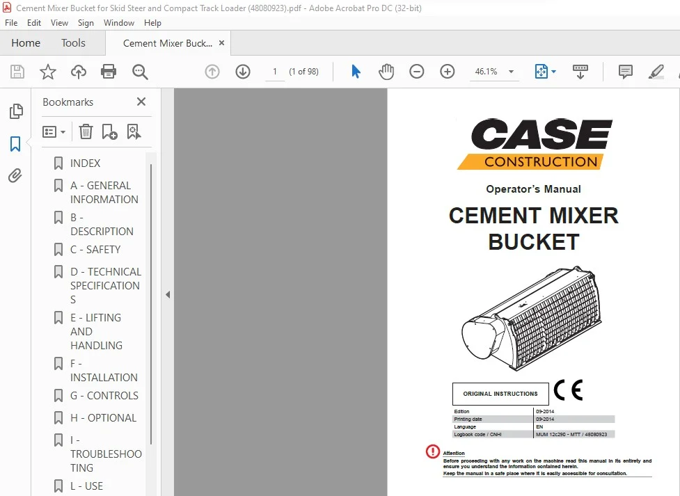
DESCRIPTION:
Case CONDOR – CONDOR SL Cement Mixer Bucket Service Manual – PDF DOWNLOAD
Introduction :
- The manufacturer declines all liability in relation to anomalies due to wrong settings.
Since our products are in continuous evolution, certain details may not exactly correspond to
those completing your equipment model. - In such cases, if you are in doubt with regard to the correct operation, consult an authorised
service centre. Never proceed by trial and error. - In order to always offer the best product, report any errors or omissions found in the manuals
supplied, especially regarding safety situations, advice for improving the equipment and our
customer service and whatever else you wish to communicate to this purpose.
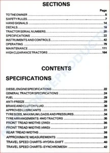
TABLE OF CONTENTS:
Case CONDOR – CONDOR SL Cement Mixer Bucket Service Manual – PDF DOWNLOAD
1 – En
WARRANTY
INSTRUCTIONS UPON DELIVERY …………………………………………………………………………………………………..V
A – GENERAL INFORMATION
LETTER UPON DELIVERY……………………………………………………………………………………………………………….5
INTRODUCTION………………………………………………………………………………………………………………………………6
HOW TO CONSULT THE MANUAL…………………………………………………………………………………………………..6
Topics not covered by the manual……………………………………………………………………………………6
Structure of the publication………………………………………………………………………………………………6
NOTES FOR THE USER…………………………………………………………………………………………………………………..6
Unauthorised modifications……………………………………………………………………………………………..6
User or machine operator………………………………………………………………………………………………..7
BUILDER…………………………………………………………………………………………………………………………………………7
CHECKING THE SUPPLIED PRODUCT…………………………………………………………………………………………….7
SYMBOLS USED……………………………………………………………………………………………………………………………..8
GLOSSARY…………………………………………………………………………………………………………………………………….8
B – DESCRIPTION
DESCRIPTION OF EQUIPMENT……………………………………………………………………………………………………..10
IDENTIFICATION DATA PLATE……………………………………………………………………………………………………….10
APPLIED SIGNALS……………………………………………………………………………………………………………………….. 11
Where to apply the signals…………………………………………………………………………………………….13
Models 150-200-250-250SL-300-300SL-350………………………………………………………13
Model 450………………………………………………………………………………………………………14
MAIN COMPONENTS…………………………………………………………………………………………………………………….15
Models 150-200-250-250SL-300-300SL-350……………………………………………………………………15
Model 450……………………………………………………………………………………………………………………16
OPTIONAL PARTS…………………………………………………………………………………………………………………………17
POSITIONING………………………………………………………………………………………………………………………………..18
EQUIPMENT STATUS…………………………………………………………………………………………………………………….19
Work standby……………………………………………………………………………………………………………….19
Prolonged shut-down…………………………………………………………………………………………………….19
Temporary stop…………………………………………………………………………………………………………….20
Working condition…………………………………………………………………………………………………………20
CHARACTERISTICS OF THE WORK CYCLE…………………………………………………………………………………..20
C – SAFETY
INTENDED USE……………………………………………………………………………………………………………………………..21
IMPROPER USE…………………………………………………………………………………………………………………………….21
CONFORMITY OF THE PRODUCT………………………………………………………………………………………………….21
FORBIDDEN BEHAVIOURS……………………………………………………………………………………………………………22
ENVIRONMENT……………………………………………………………………………………………………………………………..22
RESIDUAL RISKS AND DANGERS…………………………………………………………………………………………………23
During the use……………………………………………………………………………………………………………..23
During maintenance………………………………………………………………………………………………………23
INDEX
2 – En
GENERAL RISKS FOR THE OPERATORS AND EXPOSED PEOPLE………………………………………………..23
OPERATING INSTRUCTIONS…………………………………………………………………………………………………………24
Placing and working……………………………………………………………………………………………………..24
Moving, travelling and parking………………………………………………………………………………………..24
VISIBILITY AND LIGHTING…………………………………………………………………………………………………………….24
ELECTRIC DISCHARGES………………………………………………………………………………………………………………25
THE OPERATORS………………………………………………………………………………………………………………………….26
Operator of the equipment and driver of the operating machine…………………………………………26
Routine maintenance operator……………………………………………………………………………………….26
Site or work area safety manager…………………………………………………………………………………..26
Equipment safety manager…………………………………………………………………………………………….27
SAFETY DEVICES…………………………………………………………………………………………………………………………28
D – TECHNICAL SPECIFICATIONS
TECHNICAL SPECIFICATIONS……………………………………………………………………………………………………….29
ACOUSTICAL NOISE……………………………………………………………………………………………………………………..31
MODELS COMPATIBILITY CHART………………………………………………………………………………………………….31
E – LIFTING AND HANDLING
FOREWORD………………………………………………………………………………………………………………………………….32
SAFETY REQUIREMENTS……………………………………………………………………………………………………………..32
LIFTING…………………………………………………………………………………………………………………………………………34
Intended hooking points………………………………………………………………………………………………..34
HANDLING AND/OR STORAGE……………………………………………………………………………………………………..35
PACKING………………………………………………………………………………………………………………………………………35
Removing the packing (if present)………………………………………………………………………………….35
DIMENSIONS, WEIGHTS AND LIFTING DIAGRAMS………………………………………………………………………..36
CHECKING THE EQUIPMENT………………………………………………………………………………………………………..37
Pre-delivery checks………………………………………………………………………………………………………37
F – INSTALLATION
FOREWORD………………………………………………………………………………………………………………………………….38
INSTALLATION OF THE EQUIPMENT…………………………………………………………………………………………….39
HYDRAULIC CONNECTION……………………………………………………………………………………………………………40
ELECTRICAL CONNECTION………………………………………………………………………………………………………….41
CHECK THE CORRECT CONNECTIONS…………………………………………………………………………………………42
EQUIPMENT REMOVAL…………………………………………………………………………………………………………………43
G – CONTROLS
GENERAL WARNINGS REGARDING THE CONTROLS……………………………………………………………………44
STANDARD ELECTRICAL SWITCH CONTROLS……………………………………………………………………………..44
SAFETY DEVICES…………………………………………………………………………………………………………………………45
Transmission protective casing………………………………………………………………………………………45
Unloading outlet protection grate……………………………………………………………………………………46
INDEX
3 – En
HARNESS FOR 14 PINS CONNECTOR CONTROLS………………………………………………………………………..46
CASE Joystick controls…………………………………………………………………………………………………46
H – OPTIONAL
PROTECTION GRATE OPENING KIT………………………………………………………………………………………………47
HARNESS FOR 14-PIN CONNECTOR…………………………………………………………………………………………….48
I – TROUBLESHOOTING
TROUBLESHOOTING…………………………………………………………………………………………………………………….49
L – USE
GENERAL PRECAUTIONS……………………………………………………………………………………………………………..50
INSPECTIONS AND EXAMINATIONS BEFORE STARTING………………………………………………………………50
DURING USE…………………………………………………………………………………………………………………………………51
Climbing onto and off of the operating machine……………………………………………………………….52
ROAD CIRCULATION…………………………………………………………………………………………………………………….52
RECOMMENDATIONS FOR USING THE BUCKET IN COLD CLIMATES……………………………………………53
WORK CYCLE……………………………………………………………………………………………………………………………….54
Loading the aggregates…………………………………………………………………………………………………54
Loading the cement………………………………………………………………………………………………………54
Water loading and mixing………………………………………………………………………………………………55
Unloading…………………………………………………………………………………………………………………….55
Direct unloading………………………………………………………………………………………………55
Unloading with outlet……………………………………………………………………………………….55
Unloading with flexible hose……………………………………………………………………………..56
OPENING THE PROTECTION GRATE…………………………………………………………………………………………….57
CLOSING WITH GAS CYLINDERS (OPTIONAL)………………………………………………………………………………57
CLOSING USING SCREWS…………………………………………………………………………………………………………….57
M – MAINTENANCE
FOREWORD – GENERAL WARNINGS……………………………………………………………………………………………59
CONSULTATION OF TECHNICAL DOCUMENTS……………………………………………………………………………..61
SPARE PARTS………………………………………………………………………………………………………………………………61
BUCKET CONFIGURATION……………………………………………………………………………………………………………62
SCHEDULED MAINTENANCE………………………………………………………………………………………………………..62
Daily checks…………………………………………………………………………………………………………………62
Every 50 operating hours or every week…………………………………………………………………………62
Every 200 hours…………………………………………………………………………………………………………..62
Every year……………………………………………………………………………………………………………………62
MAINTENANCE OPERATIONS……………………………………………………………………………………………………….63
Cleaning the beton mixer bucket…………………………………………………………………………………….63
LUBRICATION……………………………………………………………………………………………………………………………….64
Preliminary information………………………………………………………………………………………………….64
Lubricating grease comparative table………………………………………………………………………….64
Lubricating points………………………………………………………………………………………………………….65
Supply grease nipples……………………………………………………………………………………..65
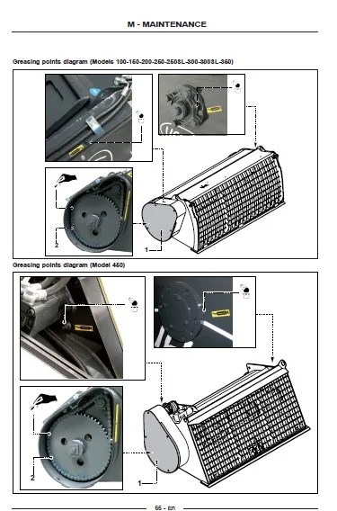
Greasing points diagram (Models 100-150-200-250-250SL-300-300SL-350)………….66
INDEX
4 – En
Greasing points diagram (Model 450)………………………………………………………………..66
TIGHTENING TORQUE TABLE……………………………………………………………………………………………………….67
ORDERING SPARE PARTS…………………………………………………………………………………………………………….67
PLACING THE MACHINE OUT OF SERVICE FOR A PROLONGED PERIOD OF DISUSE………………….68
SERVICE LIFE……………………………………………………………………………………………………………………………….68
CONTROL REGISTER……………………………………………………………………………………………………………………69
Storage instructions………………………………………………………………………………………………………69
Instructions for the drawing up……………………………………………………………………………………….69
Authorised persons……………………………………………………………………………………………………….69
Storage of the control register………………………………………………………………………………………..69
Identification of equipment……………………………………………………………………………………………..70
Equipment delivery to first owner……………………………………………………………………………………72
Transferring the property……………………………………………………………………………………………….73
Mechanism replacement………………………………………………………………………………………………..74
Structural elements replacement…………………………………………………………………………………….74
Safety device and relevant component replacement…………………………………………………………75
Serious failures and their repairs……………………………………………………………………………………75
Periodical inspections……………………………………………………………………………………………………76
Inspections…………………………………………………………………………………………………………………..77
General ………………………………………………………………………………………………………77
Inspection before use………………………………………………………………………………………77
Intervals between inspections…………………………………………………………………………..77
Forms for periodical inspections……………………………………………………………………………………..79
N – SCRAPPING AND DISPOSAL
WARNING……………………………………………………………………………………………………………………………………..80
O – ATTACHMENTS
WIRING DIAGRAM…………………………………………………………………………………………………………………………81
Wiring kit for machines NOT equipped with electric connection……………………………81
Wiring kit for machines equipped with electric connection……………………………………82
Wiring for 14 poles connector…………………………………………………………………………..83
IMAGES PREVIEW OF THE MANUAL:
CASE CONDOR – CONDOR SL CEMENT MIXER BUCKET SERVICE MANUAL – PDF DOWNLOAD:
PLEASE NOTE:
- This is the SAME exact manual used by your dealers to fix your vehicle.
- The same can be yours in the next 2-3 mins as you will be directed to the download page immediately after paying for the manual.
- Any queries / doubts regarding your purchase, please feel free to contact [email protected]
S.V