Case Crawler Excavator CX75SR CX80 Tier 3 Service Manual 87676026 – PDF DOWNLOAD
Original price was: $95.95.$33.95Current price is: $33.95.
Case Crawler Excavator CX75SR CX80 Tier 3 Service Manual
Part No:87676026
Description
Case Crawler Excavator CX75SR CX80 Tier 3 Service Manual
FILE DETAILS:
Case Crawler Excavator CX75SR CX80 Tier 3 Service Manual
Size : 158 MB
Format : PDF
Language : English
Brand: Case
Type of machine: Crawler Excavator
Type of document: Service Manual
Model: Case Crawler Excavator CX75SR CX80 Tier 3
Part No:87676026
DESCRIPTION:
Case Crawler Excavator CX75SR CX80 Tier 3 Service Manual
GENERAL INFORMATION:
- Cleanning Clean all metal parts except bearings, in a suitable cleaning solvent or by steam cleaning. Do not use caustic soda for steam cleaning. After cleaning, dry and put oil on all parts. Clean oil passages with compressed air. Clean bearings in a suitable cleaning solvent, dry the bearings completely and put oil on the bearings.
- Inspection Check all parts when the parts are disassembled. Replace all parts that have wear or damage. Small scoring or grooves can be removed with a hone or crocus cloth. Complete a visual inspection for indications of wear, pitting and the replacement of parts necessary to prevent early failures.
- Bearings Check bearings for easy action. If bearings have a loose fit or rough action replace the bearing. Wash bearings with a suitable cleaning solvent and permit to air dry. DO NOT DRY BEARINGS WITH COMPRESSED AIR. Needle bearings Before you press needle bearings in a bore always remove any metal protrusions in the bore or edge of the bore. Before you press bearings into position put petroleum jelly on the inside and outside diameter of the bearings.
- Gears Check all gears for wear and damage. Replace gears that have wear or damage.
- Oil seals, O-rings and gaskets Always install new oil seals, O-rings and gaskets. Put petroleum jelly on seals and O-rings. Shafts Check all shafts that have wear or damage. Check the bearing and oil seal surfaces of the shafts for damage.
- Service parts Always install genuine Case service parts. When ordering refer to the Parts Catalog for the correct part number of the genuine Case replacement items.
- Failures due to the use of other than genuine Case replacement parts are not covered by warranty.
- Lubrication Only use the oils and lubricants specified in the Operator’s or Service Manuals. Failures due to the use of non-specified oils and lubricants are not covered by warranty.
- To prevent injury always follow the Warning, Caution and Danger notes in this section and throughout the manual. Put the warning tag shown below on the key for the keyswitch when servicing or repairing the machine. One warning tag is supplied with each machine. Additional tags Part Number 331-4614 are available from your service parts supplier
- Long storage can lead to the accumulation of impurities and condensation in the fuel. Engine trouble can often be traced to the presence of water in the fuel. The storage tank must be placed outside and the temperature of the fuel should be kept as low as possible.
- Drain off water and impurities regularly.
CASE CRAWLER EXCAVATOR CX75SR CX80 TIER 3 SERVICE MANUAL 87676026 – PDF DOWNLOAD:
IMAGES PREVIEW OF THE MANUAL:
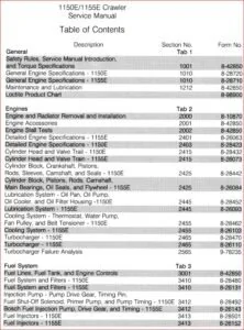
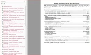
TABLE OF CONTENTS:
Case Crawler Excavator CX75SR CX80 Tier 3 Service Manual
DIVISION/SECTION SECTION N° REFERENCE N°
1 GENERAL INFORMATION
Safety, general information and standard torque data 1001 7-27691NA
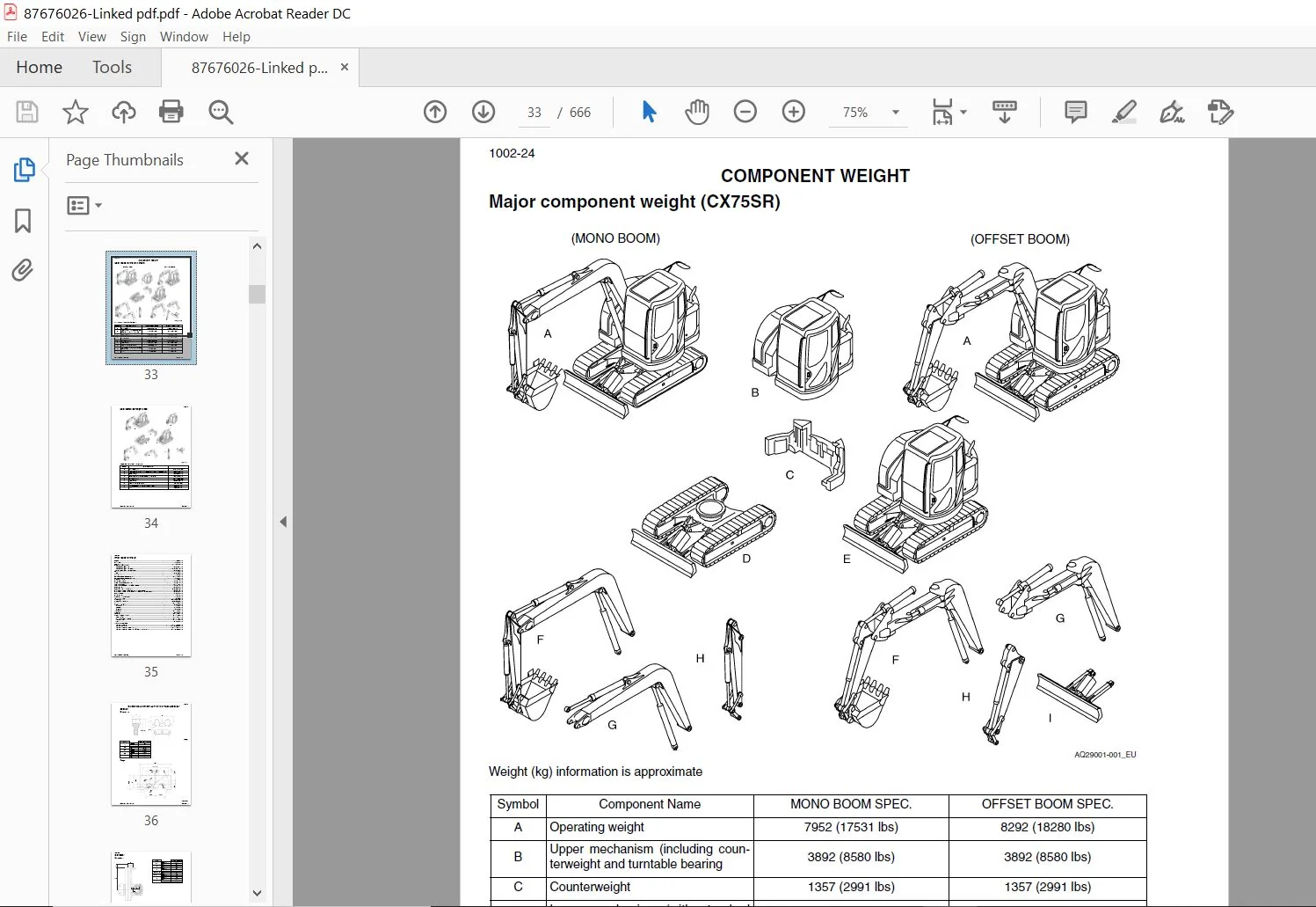
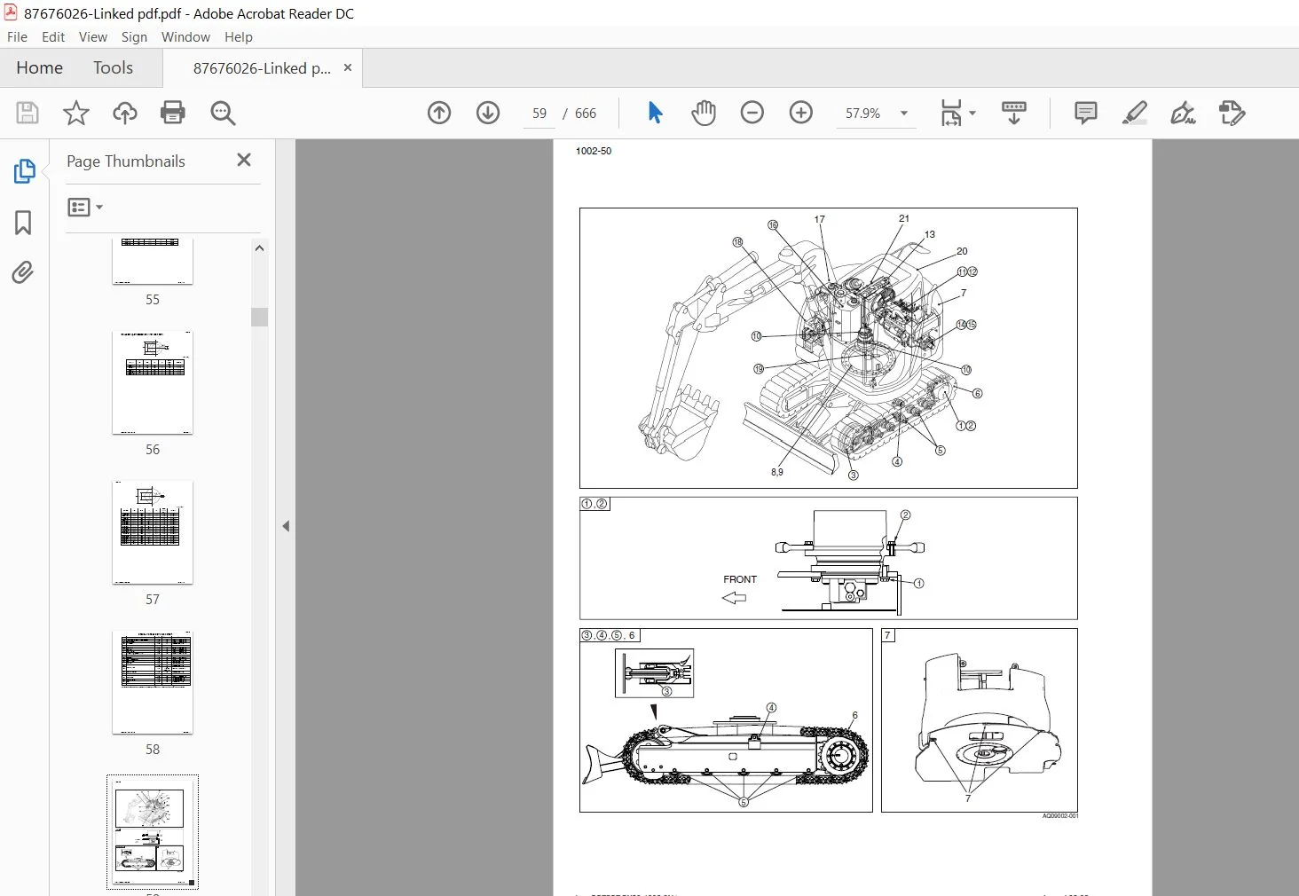
General specifications and special torque setting 1002 SC75SRCX80-1002-0NA
2 ENGINE
Removal and installation of the engine 2000 SM75SR2000-0EN
Engine specifications *
Disassembly and assembly of the engine *
3 FUEL SYSTEM
Removal and installation of the fuel tank 3001 SM75SR3001-0EN
Fuel engine system *
4 ELECTRICAL SYSTEM
Electrical and engine functions and service support 4001 SC75SRCX80-4001-0NA
Electrical equipment and electrical circuit diagrams 4020 SC75SRCX80-4020-0NA
5 UNDERCARRIAGE
Removal and installation of tracks 5001 SM75SR5001-0EN
Rollers 5003 SM75SR5003-0EN
Take-up roller 5005 SM75SR5005-0EN
6 DRIVE TRAIN
Removal and installation of the drive motor and
final drive transmission 6001 SM75SR6001-0EN
Disassembly and assembly of the drive motor and
final drive transmission 6002 SM75SR6002-0EN
Removal and installation of the swing motor and
swing reduction gear 6003 SM75SR6003-0EN
Disassembly and assembly of the swing reduction gear 6004 See 8019
7 UNDERCARRIAGE HYDRAULICS
* Consult the Engine Service Manual
Lep SM75SRTOC-0NA Issued 08-08
DIVISION/SECTION SECTION N° REFERENCE N°
8 UPPERSTRUCTURE HYDRAULICS
Specifications, troubleshooting, checks and
hydraulic pressure settings 8001 SC75SRCX80-8001-0NA
Removal and installation of the hydraulic reservoir 8002 SM75SR8002-0EN
Removal and installation of the main hydraulic pump 8003 SM75SR8003-0EN
Removal and installation of the main hydraulic control valve – CX75SR 8004 SM75SR8004-0EN
Removal and installation of the main hydraulic control valve – CX80 8004 SM80-8004-0EN
Removal and installation of the attachment cylinders 8005 SM75SR8005-0EN
Removal and installation of the hydraulic swivel 8006 SM75SR8006-0EN
Removal and installation of the pilot blocs 8007 SM75SR8007-0EN
Disassembly and assembly of the main hydraulic pump 8010 SM75SR8010-0EN
Disassembly and assembly of the main hydraulic control valve – CX75SR 8011 SM75SR8011-0EN
Disassembly and assembly of the main hydraulic control valve – CX80 8011 SM80-8011-0EN
Disassembly and assembly of the attachment cylinders 8012 SM75SR8012-0EN
Disassembly and assembly of the hand control levers 8013 SM75SR8013-0EN
Disassembly and assembly of the foot control levers 8014 SM75SR8014-0EN
Disassembly and assembly of the solenoid valve block 8015 SM75SR8015-0EN
Disassembly and assembly of the cushion valve 8016 SM75SR8016-0EN
Disassembly and assembly of the hydraulic swivel 8018 SM75SR8018-0EN
Disassembly and assembly of the swing motor 8019 SM75SR8019-0EN
Hydraulic functions 8020 SC75SRCX80-8020-0NA
Hydraulic component functions 8030 SC75SRCX80-8030-0NA
9 UPPERSTRUCTURE
Air conditioning unit 9007 SM75SR9007-0EN
Large size hydraulic schematics – CX75SR Pocket 87725725A
Large size electrical schematics – CX75SR Pocket 87742052A
Large size hydraulic schematics – CX80 Pocket KAJ11600-E00
Large size electrical schematics – CX80 Pocket
PLEASE NOTE:
- This is the SAME exact manual used by your dealers to fix your vehicle.
- The same can be yours in the next 2-3 mins as you will be directed to the download page immediately after paying for the manual.
- Any queries / doubts regarding your purchase, please feel free to contact [email protected]