CASE CX135SR TIER 3 CX135SR TIER 3 CRAWLER EXCAVATOR SERVICE REPAIR MANUAL (84187486A NA) CASE – PDF DOWNLOAD
Original price was: $83.95.$41.95Current price is: $41.95.
Case Crawler Excavator CX135SR Tier 3 Service Manual
Size : 71.6 MB
Format : PDF
Language : English
Brand: Case
Type of machine: Crawler Excavator
Type of document: Service Manual
Model: Case Crawler Excavator CX135SR Tier 3
Part No: 84187486A NA
Description
CASE CX135SR TIER 3 CX135SR TIER 3 CRAWLER EXCAVATOR SERVICE REPAIR MANUAL (84187486A NA) CASE
File Details:
Case Crawler Excavator CX135SR Tier 3 Service Manual
Size : 71.6 MB
Format : PDF
Language : English
Brand: Case
Type of machine: Crawler Excavator
Type of document: Service Manual
Model: Case Crawler Excavator CX135SR Tier 3
Part No: 84187486A NA
CASE CX135SR TIER 3 CX135SR TIER 3 CRAWLER EXCAVATOR SERVICE REPAIR MANUAL (84187486A NA) CASE – PDF DOWNLOAD:
Image Preview:
Description:
- Cleanning
Clean all metal parts except bearings, in a suitable cleaning solvent or by steam cleaning. Do not use caustic soda for steam cleaning. After cleaning, dry and put oil on all parts. Clean oil passages with compressed air. Clean bearings in a suitable cleaning solvent, dry the bearings completely and put oil on the bearings. - Inspection
Check all parts when the parts are disassembled. Replace all parts that have wear or damage. Small scoring or grooves can be removed with a hone or crocus cloth. Complete a visual inspection for indications of wear, pitting and the replacement of parts necessary to prevent early failures. - Bearings
Check bearings for easy action. If bearings have a loose fit or rough action replace the bearing. Wash bearings with a suitable cleaning solvent and permit to air dry. DO NOT DRY BEARINGS WITH COMPRESSED AIR. - Needle bearings
Before you press needle bearings in a bore always remove any metal protrusions in the bore or edge of the bore. Before you press bearings into position put petroleum jelly on the inside and outside diameter of the bearings. - Gears
Check all gears for wear and damage. Replace gears that have wear or damage. - Oil seals, O-rings and gaskets
Always install new oil seals, O-rings and gaskets. Put petroleum jelly on seals and O-rings. - Shafts
Check all shafts that have wear or damage. Check the bearing and oil seal surfaces of the shafts for damage. - Service parts
Always install genuine Case service parts. When ordering refer to the Parts Catalog for the correct part number of the genuine Case replacement items. Failures due to the use of other than genuine Case replacement parts are not covered by warranty. - Lubrication
Only use the oils and lubricants specified in the Operator’s or Service Manuals. Failures due to the use of non-specified oils and lubricants are not covered by warranty.
Table Of Contents:
1 GENERAL INFORMATION
Safety, general information and standard torque data 1001 7-27691NA
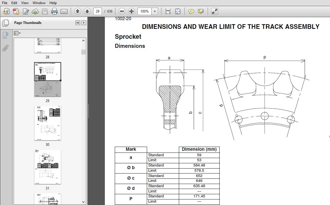
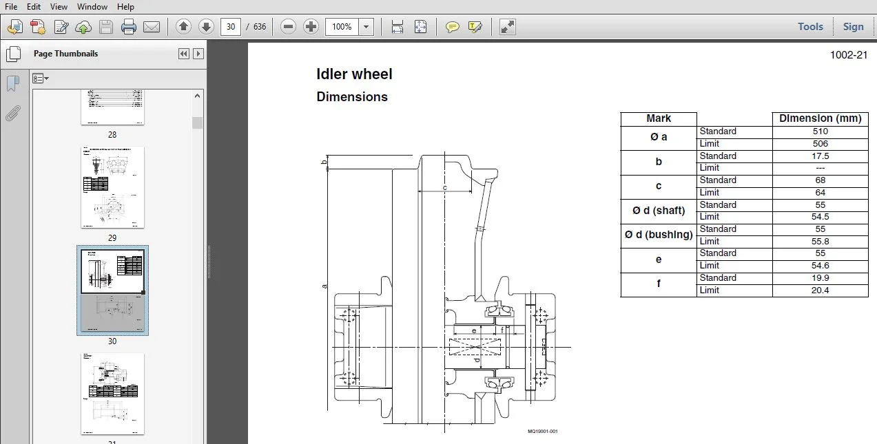
General specifications and special torque setting 1002 SC135SR1002-1NA
2 ENGINE
Removal and installation of the engine 2000 SM135SR2000-0EN
Engine specifications *
Disassembly and assembly of the engine *
3 FUEL SYSTEM
Removal and installation of the fuel tank 3001 SM135SR3001-0EN
Fuel engine system *
4 ELECTRICAL SYSTEM
Electrical and engine functions and service support 4001 SC135SR4001-1NA
5 UNDERCARRIAGE
Removal and installation of tracks 5001 SM75SR5001-0EN
Rollers 5003 SM135SR5003-0EN
Take-up roller 5005 SM135SR5005-0EN
6 DRIVE TRAIN
Removal and installation of the drive motor and
final drive transmission 6001 SM135SR6001-0EN
Disassembly and assembly of the drive motor and
final drive transmission 6002 SM135SR6002-0EN
Removal and installation of the swing motor and
swing reduction gear 6003 SM135SR6003-0EN
Disassembly and assembly of the swing reduction gear 6004 SM135SR6004-0EN
7 UNDERCARRIAGE HYDRAULICS
8 UPPERSTRUCTURE HYDRAULICS
Specifications, troubleshooting, checks and
hydraulic pressure settings 8001 SC135SR8001-1NA
Removal and installation of the hydraulic reservoir 8002 SM135SR8002-0EN
Removal and installation of the main hydraulic pump 8003 SM135SR8003-0EN
Removal and installation of the main hydraulic control valve 8004 SM135SR8004-0EN
Removal and installation of the attachment cylinders 8005 SM135SR8005-0EN
Removal and installation of the hydraulic swivel 8006 SM135SR8006-0EN
Removal and installation of the pilot blocs 8007 SM75SR8007-0EN
Disassembly and assembly of the main hydraulic pump 8010 SM135SR8010-0EN
Disassembly and assembly of the main hydraulic control valve 8011 SM135SR8011-0EN
Disassembly and assembly of the attachment cylinders 8012 SM135SR8012-0EN
Disassembly and assembly of the hand control levers 8013 SM75SR8013-0EN
Disassembly and assembly of the foot control levers 8014 SM135SR8014-0EN
Disassembly and assembly of the solenoid valve block 8015 SM75SR8015-0EN
Disassembly and assembly of the cushion valve 8016 SM135SR8016-0EN
Disassembly and assembly of the hydraulic swivel 8018 SM135SR8018-0EN
Disassembly and assembly of the swing motor 8019 SM135SR8019-0EN
Hydraulic functions 8020 SC135SR8020-0NA
Hydraulic component functions 8030 SC135SR8030-0NA
9 UPPERSTRUCTURE
Air conditioning unit 9007 SM75SR9007-0EN
Large size hydraulic schematics Pocket 87746261A
Large size electrical schematics Pocket 87746254A
Please Note:
⦁ This is the SAME MANUAL used by the dealerships to diagnose your vehicle
⦁ No waiting for couriers / posts as this is a PDF manual and you can download it within 2 minutes time once you make the payment.
⦁ Your payment is all safe and the delivery of the manual is INSTANT – You will be taken to the DOWNLOAD PAGE.
⦁ So have no hesitations whatsoever and write to us about any queries you may have : heydownloadss @gmail.com