Case CX240 Crawler Excavator Service Manual 7-29051 – PDF DOWNLOAD
Original price was: $89.95.$29.95Current price is: $29.95.
Case CX240 Crawler Excavator Service Manual 7-29051 – PDF DOWNLOAD
Description
Case CX240 Crawler Excavator Service Manual 7-29051 – PDF DOWNLOAD
DESCRIPTION:
Case CX240 Crawler Excavator Service Manual 7-29051 – PDF DOWNLOAD
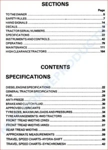
TABLE OF CONTENTS:
Case CX240 Crawler Excavator Service Manual 7-29051 – PDF DOWNLOAD
1 GENERAL INFORMATION
СХ240 Crawler Excavators
ТаЫе of Contents
SECTION №
Safety, general information and standard torque data ………………………………. 1001
General specifications and special torque setting …………………………………….. 1002
Numerical value conversion tаЫе ………………………………………………………….. 1003
2 ENGINE
Removal and installation of the engine …………………………………………………… 2000
Radiator and oil-cooler …………………………………………………………………………. 2001
Engine specifications ………………………………………………………………………………… *
DisassemЫy and assemЫy of the engine …………………………………………………….. *
3 FUEL SYSTEM
Fuel tank ……………………………………………………………………………………………. 3001
Fuel engine system …………………………………………………………………………………… *
4 ELECTRICAL SYSTEM
Electrical system, electrical and electronic trouЫeshooting ………………………. .4001
lnspection and maintenance of batteries and connecting а booster battery … .4002
5 UNDERCARRIAGE
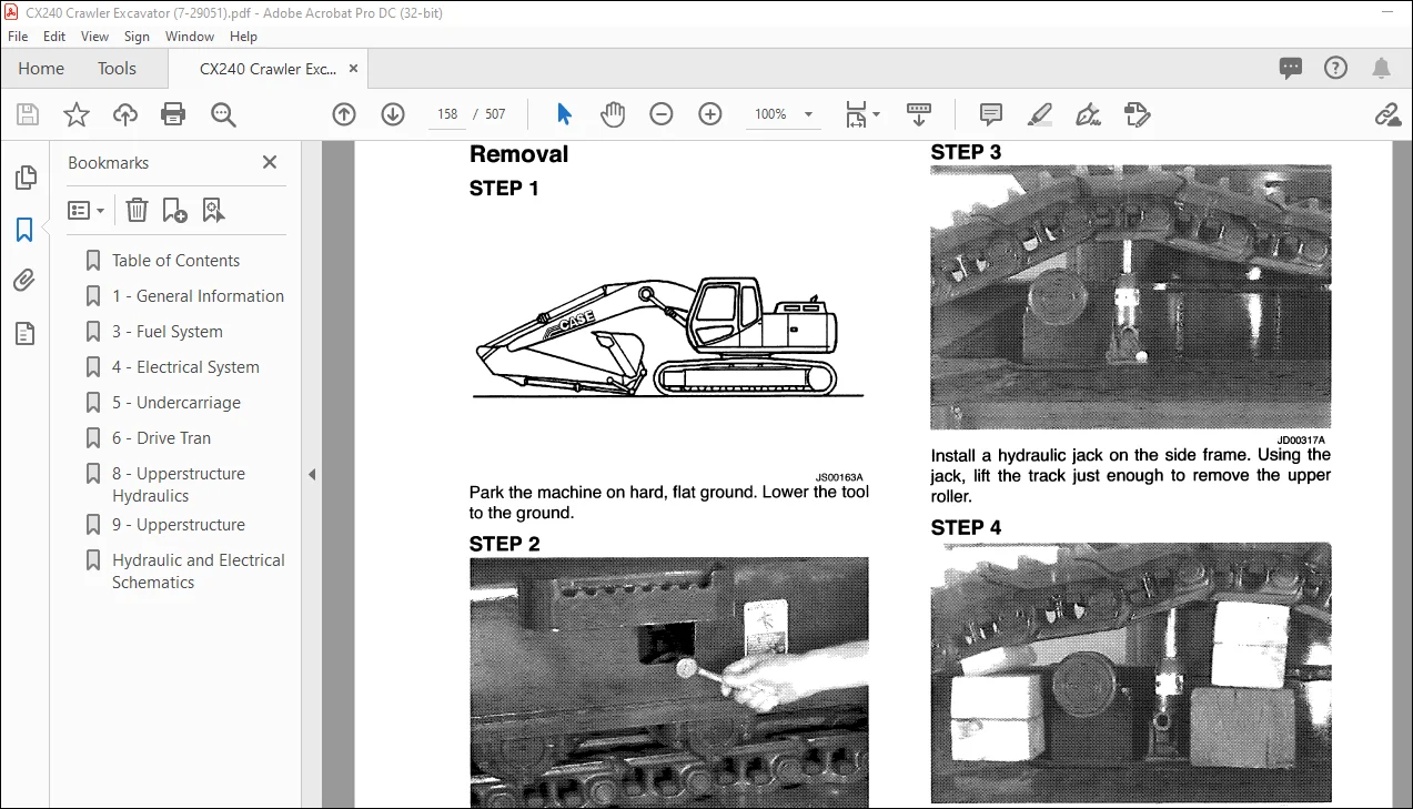
Removal and installation of tracks …………………………………………………………. 5001
Rollers ……………………………………………………………………………………………….. 5003
Sprocket …………………………………………………………………………………………….. 5004
ldler wheel and tension shock absorber …………………………………………………. 5005
6 DRIVE TRAIN
Drive motor and final drive transmission removal and installation ………………. 6001
Drive motor and final drive transmission disassemЫy and assemЫy ………….. 6002
Swing reduction gear, removal and installation ………………………………………… 6003
Swing reduction gear, disassemЫy and assemЫy …………………………………… 6004
7 UNDERCARRIAGE HYDRAULICS
8 UPPERSTRUCTURE HYDRAULICS
Depressurising and decontaminating the hydraulic system, use of the
vacuum pump and Ыeeding the components ………………………………………. 8000
Specifications, trouЫeshooting, checks and hydraulic pressure settings …….. 8001
Hydraulic reservoir removal and installation ……………………………………………. 8002
Main and pilot pumps, removal and installation ……………………………………….. 8003
Main hydraulic control valve, removal and installation ………………………………. 8004
Attachment cylinders, removal and installation ………………………………………… 8005
Hydraulic swivel, removal and installation ………………………………………………. 8006
Pilot Ыосs, removal and installation ……………………………………………………….. 8007
Swing motor, removal and installation ……………………………………………………. 8008
DisassemЫy and assemЫy of the free swing valve ………………………………….. 8009
Main hydraulic pump, disassemЫy and assemЫy ……………………………………. 801 О
Main hydraulic control valve, disassemЬly and assemЬly ………………………….. 8011
Attachment cylinders, disassemЫy and assemЫy ……………………………………. 8012
Hand control levers, disassemЫy and assemЫy ……………………………………… 8013
Foot control levers, disassemЫy and assemЫy ………………………………………. 8014
Six-solenoid valves, disassemЫy and assemЫy ……………………………………… 8015
Caution valve, disassemЫy and assemЫy ……………………………………………… 8016
Safety valve ……………………………………………………………………………………….. 8017
Hydraulic swivel, disassemЫy and assemЫy ………………………………………….. 8018
Swing motor, disassemЫy and assemЫy ……………………………………………….. 8019
Hydraulic functions ………………………………………………………………………………. 8020
9 UPPERSTRUCTURE
Upperstructure, turntaЫe and counterweight …………………………………………… 9002
Boom, dipper and bucket ……………………………………………………………………… 9003
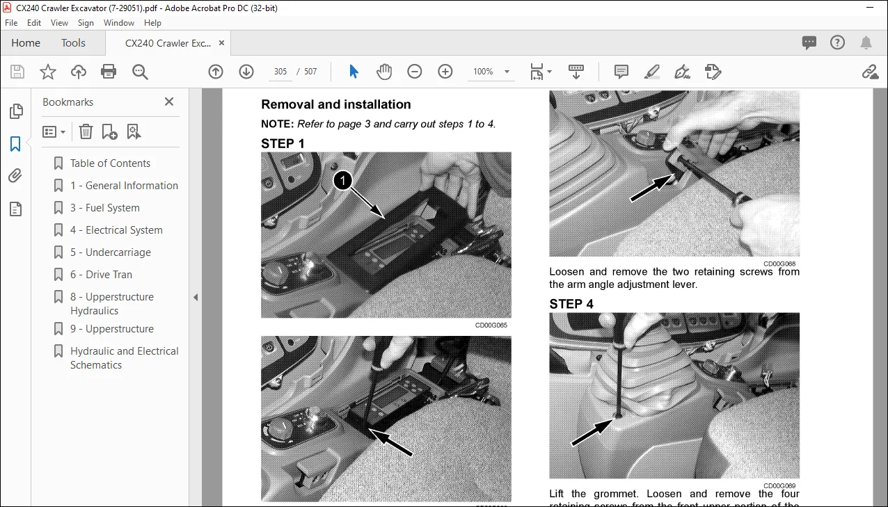
Seat and seat belt ……………………………………………………………………………….. 9004
СаЬ and саЬ equipment ……………………………………………………………………….. 9005
Air conditioner trouЫeshooting and system checks …………………………………… 9006
Air conditioning unit disassemЫy and assemЫy ………………………………………. 9007
Air conditioning servicing ……………………………………………………………………… 9008
Air conditioning components …………………………………………………………………. 9009
Large format hydraulic and electrical schematics ………………………………….. Pocket
IMAGES PREVIEW OF THE MANUAL:
Contact us: [email protected]
PLEASE NOTE:
- This is the SAME manual used by the dealers to troubleshoot any faults in your vehicle. This can be yours in 2 minutes after the payment is made.
- Contact us at [email protected] should you have any queries before your purchase or that you need any other service / repair / parts operators manual.
S.V