Case CX300C Tier 4 Crawler Excavator Service Repair Manual Case CX300C – PDF Download
Original price was: $95.00.$34.00Current price is: $34.00.
Case CX300C Tier 4 Crawler Excavator Service Repair Manual
Part Numbers: 84541700, 84541701, 84541702, 84541703, 84541704, 84541705, 84541706, 84541707
Description
Case CX300C Tier 4 Crawler Excavator Service Repair Manual Case CX300C
CASE CX300C TIER 4 CRAWLER EXCAVATOR SERVICE REPAIR MANUAL CASE CX300C – PDF DOWNLOAD:
SCREENSHOOTS OF THE MANUAL:
SAMPLE PAGE FROM THE MANUAL:
Case CX300C Tier 4 Crawler Excavator Service Repair Manual Case CX300C
- CLEANING
Clean all metal parts except bearings, in a suitable cleaning solvent or by steam cleaning.
Do not use caustic soda for steam cleaning.
After cleaning, dry and put oil on all parts.
Clean oil passages with compressed air.
Clean bearings in a suitable cleaning solvent,
dry the bearings completely and put oil on the bearings. - INSPECTION
Check all parts when the parts are disassembled.
Replace all parts that have wear or damage.
Small scoring or grooves can be removed with a hone or crocus cloth.
Complete a visual inspection for indications of wear, pitting and the replacement of parts necessary to prevent early
failures. - BEARINGS
Check bearings for easy action.
If bearings have a loose fit or rough action replace the bearing.
Wash bearings with a suitable cleaning solvent and permit to air dry.
DO NOT DRY BEARINGS WITH COMPRESSED AIR.
TABLE OF CONTENTS:
Case CX300C Tier 4 Crawler Excavator Service Repair Manual Case CX300C
1 – GENERAL INFORMATION……………………………………………. 2
Section 1001 – Safety, general information and standard torque data…. 2
Section 1002A – Specifications………………………………….. 14
Section 1002B – Main Equipment Table (CX300C)…………………….. 24
Section 1002C – Main Unit Weight………………………………… 38
Section 1002D – Maintenance Standards……………………………. 44
Section 1002E – Bolt Size and Torque Table……………………….. 70
Section 1002F – Overall View……………………………………. 78
Section 1003 – List of special tools…………………………….. 86
Section 1004 – FLUIDS AND LUBRICANTS……………………………..126
Section 1005 – Conversion Table………………………………….132
Section 1900 – Abbreviations…………………………………….138
2 – ENGINE………………………………………………………………………………………. 2
Section 2000 – Removal and Installation of Engine Assembly………………………………………… 2
Section 2001 – Removal and installation of the fuel cooler engine
inter-cooler radiator and oil cooler…. 14
Section 2004 – Removal and Installation of Turbo Charger………………………………………….. 30
Section 2005 – Removal and Installation of EGR Cooler and EGR Valve………………………………… 38
Section 2006 – Removal and Installation of Engine Hood……………………………………………. 46
Section 2007 – Removal and Installation of Muffler……………………………………………….. 52
Section 2401 – Primary specifications…………………………………………………………… 58
Section 2415 – Removal and Installation of Cylinder Head………………………………………….. 64
Section 2425 – Removal and Installation of Cylinder Block………………………………………….118
Section 2445 – Lubrication System……………………………………………………………….176
Section 2455 – Cooling System…………………………………………………………………..224
Section 2465 – Removal and Installation of Exhaust Manifold………………………………………..240
Section 2470 – Disassembly, Removal and Installation of DPD Assembly………………………………..250
3 – FUEL SYSTEM…………………………………………………………………………………..260
Section 3001 – Removal and Installation of Fuel Tank………………………………………………260
Section 3004A – Removal and Installation of Fuel Supply Pump……………………………………….268
Section 3004B – Removal and Installation of Common Rail Assembly……………………………………276
Section 3005 – Removal and Installation of Injector……………………………………………….290
4 – ELECTRICAL SYSTEM……………………………………. 2
Section 4001A – Electrical and Engine Basic Functions……. 2
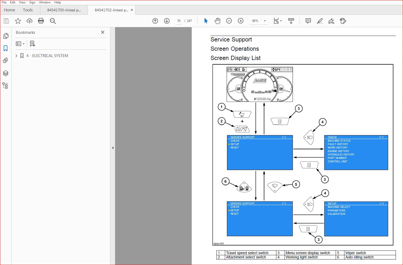
Section 4001B – Service Support……………………….. 66
Section 4001C – Function, Structure, Operation…………..104
Section 4001E – Symptom……………………………….186
Section 4001F – Functional Inspection…………………..204
Section 4001G – Maintenance precautions…………………220
Section 4004 – Removal and Installation of Starter Motor….228
Section 4005 – Removal and Installation of Alternator…….234
Section 4008 – Preheating System……………………….240
4 – ELECTRICAL SYSTEM…………………………………. 2
Section 4020A – Electrical Equipment Layout Diagram…… 2
Section 4020B – Connection Connector Pin Layout………. 42
Section 4020C – Sequence Circuit Diagram…………….. 48
Section 4021 – Engine-side DTC List…………………. 66
Section 4022 – Main Unit-side DTC List………………. 72
Section 4023B – Introduction to the trouble diagnosis…. 78
Section 4023D – Engine Control System……………….. 92
Section 4023G – Engine-side Trouble………………….112
Section 4023H – Main Unit-side Trouble……………….190
Section 4023K – Data Reference Values………………..288
Section 4040 – Electrical Wiring Diagram……………..294
5 – UNDERCARRIAGE………………………………………….. 2
Section 5001A – Removal and Installation of Shoe Assembly…… 2
Section 5001B – Removal and Installation of Shoe Plate……… 10
Section 5003A – Removal and Installation of Upper Roller……. 16
Section 5003B – Assembly and Disassembly of Upper Roller……. 22
Section 5003C – Removal and Installation of Lower Roller……. 36
Section 5003D – Assembly and Disassembly of Lower Roller……. 42
Section 5004 – Removal and Installation of Drive Sprocket…… 56
Section 5005A – Removal and Installation of Take-up Roller….. 64
Section 5005B – Assembly and Disassembly of Take-up Roller….. 70
Section 5005C – Removal and Installation of Grease Cylinder…. 84
Section 5005D – Assembly and Disassembly of Grease Cylinder…. 90
6 – DRIVE TRAIN…………………………………………….100
Section 6001 – Removal and Installation of Travel Motor……..100
Section 6002 – Assembly and Disassembly of Travel Motor……..110
Section 6003 – Removal and Installation of Swing Unit……….158
Section 6004 – Assembly and Disassembly of Swing Unit……….166
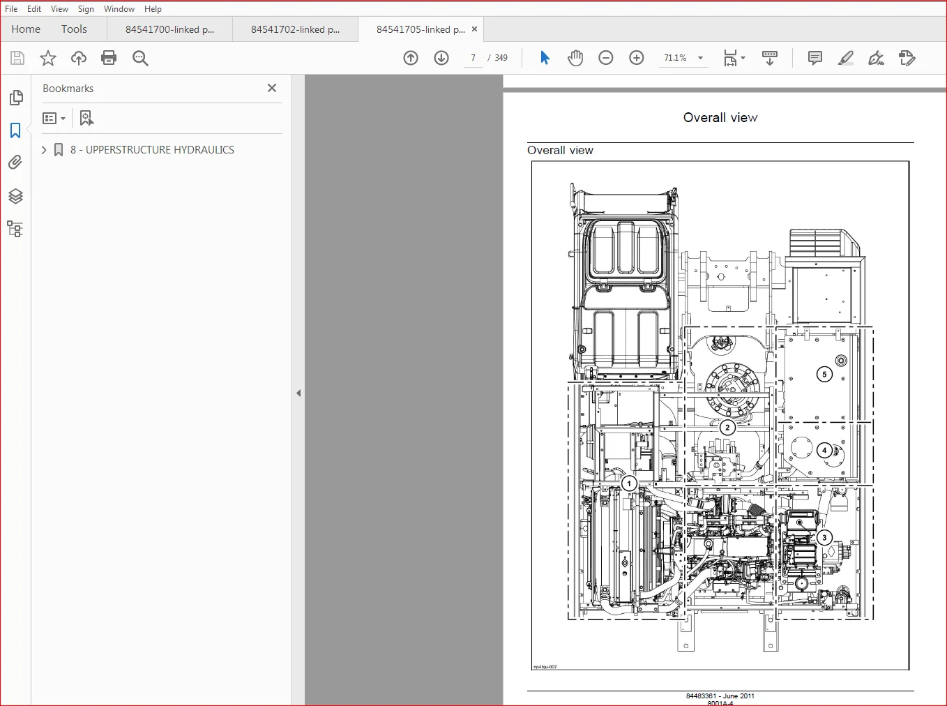
8 – UPPERSTRUCTURE HYDRAULICS…………………………………………………………. 2
Section 8001A – Overall view………………………………………………………. 2
Section 8001B – Port Diagram………………………………………………………. 18
Section 8001D – Pressure Measurement and Adjustment Procedures………………………… 42
Section 8001E – Hydraulic Pump Flow Measurement Procedures……………………………. 68
Section 8001F – Drain Volume Measurement Procedures………………………………….. 78
Section 8001G – Air Bleed Procedure………………………………………………… 86
Section 8002 – Removal and Installation of Hydraulic Oil Tank…………………………. 96
Section 8003 – Removal and Installation of Hydraulic Pump……………………………..106
Section 8004 – Removal and Installation of Control Valve………………………………116
Section 8005A – Removal and Installation of Bucket Cylinder……………………………128
Section 8005B – Removal and Installation of Arm Cylinder………………………………138
Section 8005C – Removal and Installation of Boom Cylinder……………………………..148
Section 8006 – Removal and Installation of Center Joint……………………………….158
Section 8007A – Removal and Installation of Travel Remote Control Valve…………………166
Section 8007B – Removal and Installation of Operation Remote Control Valve………………174
Section 8007C – Removal and Installation of 5 Stack Solenoid…………………………..188
Section 8007D – Removal and Installation of Cushion Valve……………………………..200
Section 8008 – Procedures for Assembly and Disassembly of Hydraulic
Pump Main Unit……….210
Section 8010 – Pump Main Unit Maintenance Standards…………………………………..220
Section 8011 – Procedures for Assembly and Disassembly of Control Valve…………………236
Section 8012 – Procedures for Operation/Assembly and Disassembly of
Hydraulic Cylinder……270
Section 8013 – Procedures for Assembly and Disassembly of Operation
Remote Control Valve….306
Section 8014 – Procedures for Assembly and Disassembly of Travel
Remote Control Valve…….322
Section 8016 – Assembly and Disassembly of Cushion Valve………………………………340
8 – UPPERSTRUCTURE HYDRAULICS………………………………………………………………… 2
Section 8017A – Removal and Installation of Arm HBCV………………………………………… 2
Section 8017B – Removal and Installation of Boom HBCV……………………………………….. 8
Section 8018 – Assembly and Disassembly of Center Joint……………………………………… 16
Section 8019 – Assembly and Disassembly of Swing Motor………………………………………. 28
Section 8020A – Explanation of Hydraulic Circuit and Operations (standard
model)……………….. 50
Section 8020B – Explanation of Hydraulic Circuit and Operations (option)……………………….134
Section 8030A – Structure and Operation Explanation of Hydraulic Pump………………………….148
Section 8030B – Structure and Operation Explanation of Travel Motor……………………………168
Section 8030C – Structure and Operation Explanation of Swing Motor…………………………….188
Section 8030D – Control Valve……………………………………………………………..202
Section 8030E – 5 Stack Solenoid Valve Operation Explanation………………………………….248
Section 8030F – Structure and Operation Explanation of Upper Pilot Valve
(remote control valve)…..254
Section 8030G – Structure and Operation Explanation of Travel Pilot Valve
(remote control valve)….266
Section 8030H – Structure and Operation Explanation of Cushion Valve…………………………..276
9 – UPPERSTRUCTURE……………………………………………… 2
Section 9002 – Removal and Installation of Counterweight………… 2
Section 9003A – Removal and Installation of Bucket……………… 8
Section 9003B – Removal and Installation of Bucket Link…………. 14
Section 9003C – Removal and Installation of Arm………………… 22
Section 9003D – Removal and Installation of Boom……………….. 28
Section 9004 – Removal and Installation of Operator’s Seat………. 40
Section 9005A – Removal and Installation of Cab Assembly………… 46
Section 9005B – Removal and Installation of Wiper………………. 56
Section 9005C – Removal and Installation of Wiper Controller…….. 62
Section 9005D – Removal and Installation of Wiper Motor…………. 68
Section 9005E – Removal and Installation of Monitor…………….. 74
Section 9005F – Removal and Installation of Cab Front Glass……… 80
Section 9005G – Window Lock Adjustment Procedures………………. 86
Section 9005H – Tightening torque…………………………….. 92
Section 9006 – Air Conditioner Overall Diagram…………………. 98
Section 9007 – Assembly and Disassembly of Air Conditioner Units….152
Section 9009 – Removal and Installation of Compressor……………162
Section 9010 – Removal and Installation of Condenser…………….168
Section 9011 – Removal and Installation of Receiver Dryer………..174
Section 9015 – Work Precautions……………………………….180
PLEASE NOTE:
- This is the same manual used by the DEALERSHIPS to SERVICE your vehicle.
- The manual can be all yours – Once payment is complete, you will be taken to the download page from where you can download the manual. All in 2-5 minutes time!!
- Need any other service / repair / parts manual, please feel free to contact us at heydownloadss @gmail.com . We may surprise you with a nice offer