Case CX700B CRAWLER EXCAVATOR SERVICE REPAIR MANUAL (84124939D) Case CX700B – PDF Download
Original price was: $98.95.$40.95Current price is: $40.95.
Case Crawler Excavator CX700B Service Manual_84124939D
Size : 109 MB
Format : PDF
Language : English
Number of Pages : 1488 pages
Brand: Case
Type of machine: Excavator
Type of document: Service Manual
Model: Case Crawler Excavator CX700B
Part No: 84124939D
Description
Case CX700B CRAWLER EXCAVATOR SERVICE REPAIR MANUAL (84124939D) Case CX700B
File Details:
Case Crawler Excavator CX700B Service Manual_84124939D
Size : 109 MB
Format : PDF
Language : English
Number of Pages : 1488 pages
Brand: Case
Type of machine: Excavator
Type of document: Service Manual
Model: Case Crawler Excavator CX700B
Part No: 84124939D
CASE CX700B CRAWLER EXCAVATOR SERVICE REPAIR MANUAL (84124939D) CASE CX700B – PDF DOWNLOAD:
Image Preview:
Description:
Case CX700B CRAWLER EXCAVATOR SERVICE REPAIR MANUAL (84124939D) Case CX700B
- Cleanning
Clean all metal parts except bearings, in a suitable cleaning solvent or by steam cleaning. Do not use caustic soda for steam cleaning. After cleaning, dry and put oil on all parts. Clean oil passages with compressed air. Clean bearings in a suitable cleaning solvent, dry the bearings completely and put oil on the bearings. - Inspection
Check all parts when the parts are disassembled. Replace all parts that have wear or damage. Small scoring or grooves can be removed with a hone or crocus cloth. Complete a visual inspection for indications of wear, pitting and the replacement of parts necessary to prevent early failures. - Bearings
Check bearings for easy action. If bearings have a loose fit or rough action replace the bearing. Wash bearings with a suitable cleaning solvent and permit to air dry. DO NOT DRY BEARINGS WITH COMPRESSED AIR. - Needle bearings
Before you press needle bearings in a bore always remove any metal protrusions in the bore or edge of the bore. Before you press bearings into position put petroleum jelly on the inside and outside diameter of the bearings. - Gears
Check all gears for wear and damage. Replace gears that have wear or damage. - Oil seals, O-rings and gaskets
Always install new oil seals, O-rings and gaskets. Put petroleum jelly on seals and O-rings. - Shafts
Check all shafts that have wear or damage. Check the bearing and oil seal surfaces of the shafts for damage. - Service parts
Always install genuine Case service parts. When ordering refer to the Parts Catalog for the correct part number of the genuine Case replacement items. Failures due to the use of other than genuine Case replacement parts are not covered by warranty. - Lubrication
Only use the oils and lubricants specified in the Operator’s or Service Manuals. Failures due to the use of non-specified oils and lubricants are not covered by warranty.
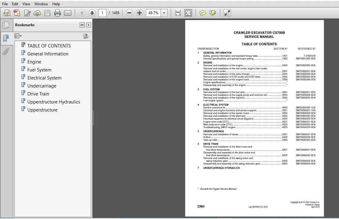
Table Of Contents:
Case CX700B CRAWLER EXCAVATOR SERVICE REPAIR MANUAL (84124939D) Case CX700B
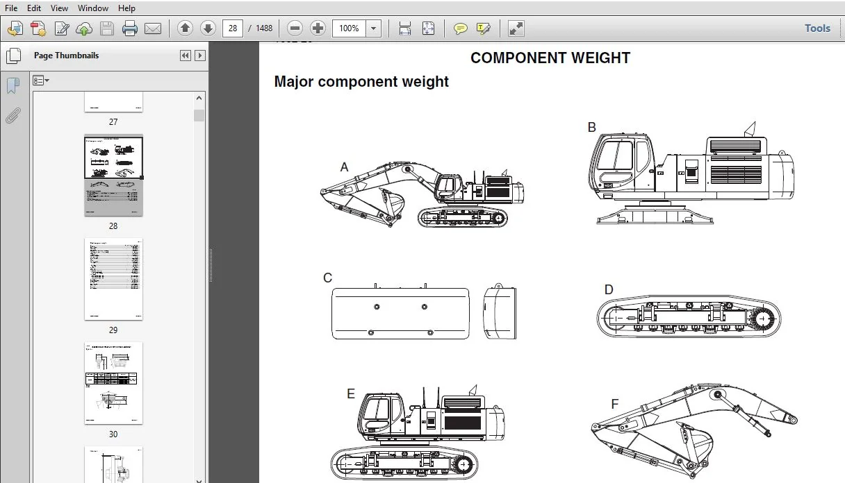
1 GENERAL INFORMATION
Safety, general information and standard torque data 1001 7-27691EN
General specifications and special torque setting 1002 SM700B1002-3EN
2 ENGINE
Removal and installation of the engine 2000 SM700B2000-0EN
Removal and installation of the fuel cooler, engine inter-cooler,
radiator and oil cooler 2001 SM700B2001-0EN
Removal and installation of the turbo charger 2004 SM700B2004-0EN
Removal and installation of EGR cooler and EGR valve 2005 SM700B2005-0EN
Removal and installation of the engine hood 2006 SM700B2006-0EN
Engine specifications
Disassembly and assembly of the engine
3 FUEL SYSTEM
Removal and installation of the fuel tank 3001 SM700B3001-0EN
Removal and installation of the supply pump and common rail 3004 SM700B3004-0EN
Removal and installation of the injectors 3005 SM700B3005-0EN
Fuel engine system
4 ELECTRICAL SYSTEM
Service connector kit 4000 SM350B4000-1EN
Electrical and engine functions and service support 4001 SM700B4001-1EN
Removal and installation of the starter motor 4004 SM700B4004-0EN
Removal and installation of the alternator 4005 SM700B4005-0EN
Electrical equipment & electrical circuit diagrams 4020 SM700B4020-0EN
Engine error code (DTC) 4021 SM700B4021-0EN
Main body error code (DTC) 4022 SM700B4022-0EN
Troubleshooting, 6WG1 engine 4023 SM700B4023-0EN
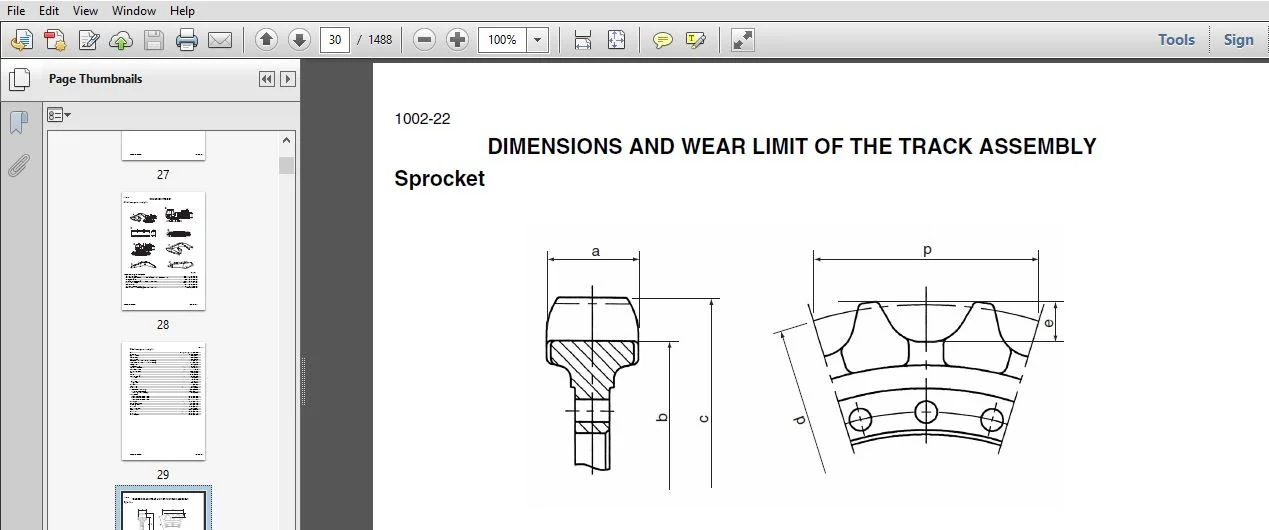
5 UNDERCARRIAGE
Removal and installation of tracks 5001 SM700B5001-0EN
Rollers 5003 SM700B5003-0EN
Take-up roller 5005 SM700B5005-0EN
6 DRIVE TRAIN
Removal and installation of the drive motor and
final drive transmission 6001 SM700B6001-0EN
Disassembly and assembly of the drive motor and
final drive transmission 6002 SM700B6002-0EN
Removal and installation of the swing motor and
swing reduction gear 6003 SM700B6003-0EN
Disassembly and assembly of the swing reduction gear 6004 SM700B6004-0EN
7 UNDERCARRIAGE HYDRAULICS
8 UPPERSTRUCTURE HYDRAULICS
Specifications, troubleshooting, checks and
hydraulic pressure settings 8001 SM700B8001-0EN
Removal and installation of the hydraulic reservoir 8002 SM700B8002-0EN
Removal and installation of the main hydraulic pump 8003 SM700B8003-0EN
Removal and installation of the main hydraulic control valve 8004 SM700B8004-0EN
Removal and installation of the attachment cylinders 8005 SM700B8005-0EN
Removal and installation of the hydraulic swivel 8006 SM700B8006-0EN
Removal and installation of the pilot blocs 8007 SM700B8007-0EN
Disassembly and assembly of the main hydraulic pump 8010 SM700B8010-0EN
Disassembly and assembly of the main hydraulic control valve 8011 SM700B8011-0EN
Disassembly and assembly of the attachment cylinders 8012 SM700B8012-0EN
Disassembly and assembly of the hand control levers 8013 SM130B8013-0EN
Disassembly and assembly of the foot control levers 8014 SM350B8014-0EN
Disassembly and assembly of the cushion valve 8016 SM130B8016-0EN
Removal and installation of the safety valve 8017 SM700B8017-0EN
Disassembly and assembly of the swing motor 8019 SM700B8019-0EN
Hydraulic functions 8020 SM700B8020-0EN
Hydraulic component functions 8030 SM700B8030-1EN
9 UPPERSTRUCTURE
Removal and installation of the counterweight 9002 SM700B9002-0EN
Removal and installation of the boom, dipper and bucket 9003 SM700B9003-0EN
Removal and installation of the seat 9004 SM130B9004-0EN
Removal and installation of the cab and cab equipment 9005 SM130B9005-0EN
Air conditioner functions and troubleshooting 9006 SM700B9006-1EN
Air conditioning unit 9007 SM700B9007-0EN
Air conditioning components 9009 SM700B9009-0EN
Removal and installation of the attachment, counterweight
and side frame 9010 SM700B9010-0EN
Large size hydraulic schematics Pocket KWJ11230-E02
Large size electrical schematics Pocket KWR10070-E04
Please Note:
⦁ This is the SAME exact manual used by your dealers to fix your vehicle.
⦁ The same can be yours in the next 2-3 mins as you will be directed to the download page immediately after paying for the manual.
⦁ Any queries / doubts regarding your purchase, please feel free to contact [email protected]