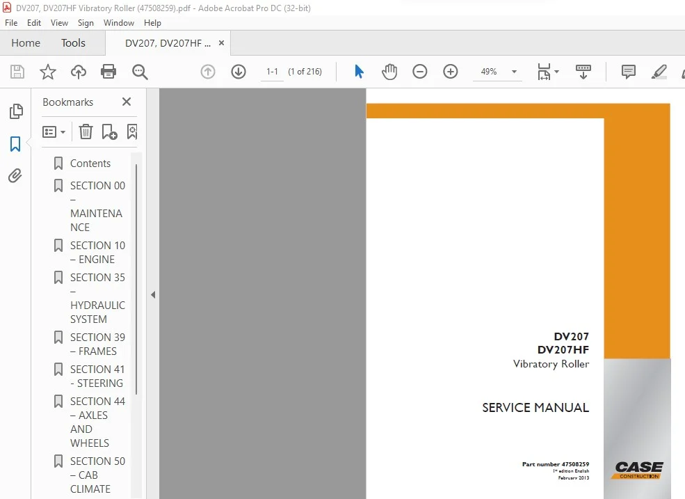
Case DV207 DV207HF Vibratory Roller Service Manual PN 47508259 – PDF DOWNLOAD
Original price was: $86.95.$28.95Current price is: $28.95.
Case DV207 DV207HF Vibratory Roller Service Manual PN 47508259 – PDF DOWNLOAD
Description
Case DV207 DV207HF Vibratory Roller Service Manual PN 47508259 – PDF DOWNLOAD
DESCRIPTION:
Case DV207 DV207HF Vibratory Roller Service Manual PN 47508259 – PDF DOWNLOAD
MAINTENANCE – CHAPTER 1:
- This service manual is divided into several chapters. It includes technical and assembly data, adjustment guidelines
and instructions in the use of special tools, jigs and aids. - The primary purpose of this Service Manual is to provide basic information on removal, installation and servicing/
repair of the machine’s main groups.
Machine group identifi cation in this manual corresponds to the Spare Parts Catalog. - Before beginning work, we recommend that you mark any removed parts that will be reinstalled and that you cover
- all holes in individual hydraulic system parts to prevent hydraulic circuit contamination.
When installing individual parts in the machine, tighten individual bolts or nuts as indicated in the torque tables
(appendix) unless otherwise indicated in the text. - ALWAYS observe the safety instructions and precautions indicated in Chapter 2.
- The manufacturer is continually improving the products based on operational experience and the latest knowledge.
Consequently, the manufacturer reserves the right to make changes to the illustrations, descriptions, procedures
or design patterns given in this manual as developments are made.
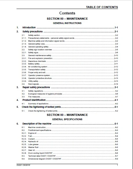
TABLE OF CONTENTS:
Case DV207 DV207HF Vibratory Roller Service Manual PN 47508259 – PDF DOWNLOAD
1. Introduction ……………………………………………………………………………………………………………..1-1
2. Safety precautions ……………………………………………………………………………………………………2-1
2.1. Safety section …………………………………………………………………………………………………………………………………2-2
2.1.1. Precautionary statements – personal safety signal words ……………………………………………………………………..2-2
2.1.2. Machine safety and information signal words ………………………………………………………………………………………2-2
2.1.3. General safety rules …………………………………………………………………………………………………………………………2-3
2.1.4. General operating safety ………………………………………………………………………………………………………………….2-4
2.2. Safety sign location overview ……………………………………………………………………………………………………………2-5
2.2.1. Safety signs ……………………………………………………………………………………………………………………………………2-6
2.3. General maintenance safety ……………………………………………………………………………………………………………2-10
2.3.1. Fire and explosion prevention ………………………………………………………………………………………………………….2-10
2.3.2. Hazardous chemicals ……………………………………………………………………………………………………………………. 2-11
2.3.3. Battery safety ……………………………………………………………………………………………………………………………….. 2-11
2.3.4. Air conditioning system ………………………………………………………………………………………………………………….2-12
2.3.5. Transportation safety ……………………………………………………………………………………………………………………..2-12
2.3.6. Proper entry and exit ……………………………………………………………………………………………………………………..2-12
2.3.7. Operator presence system ……………………………………………………………………………………………………………..2-12
2.3.8. Operator protective structure …………………………………………………………………………………………………………..2-13
2.3.9. Utility safety ………………………………………………………………………………………………………………………………….2-13
2.4. Hand signals …………………………………………………………………………………………………………………………………2-14
3. Repair safety precautions …………………………………………………………………………………………3-1
3.1. Safety regulations ……………………………………………………………………………………………………………………………3-2
3.2. Ecological measures & hygiene principles ………………………………………………………………………………………….3-6
3.3. Fire measures …………………………………………………………………………………………………………………………………3-7
4. Product identifi cation ………………………………………………………………………………………………..4-1
4.1. Summary of applications ………………………………………………………………………………………………………………….4-2
5. Check the tightening of bolted joints …………………………………………………………………………..5-1
5.1. Check the tightening of bolted joints …………………………………………………………………………………………………..5-2
SECTION 00 – MAINTENANCE
GENERAL SPECIFICATIONS
6. Description of the machine ……………………………………………………………………………………….6-1
6.1. Machine construction ……………………………………………………………………………………………………………………….6-2
6.2. Fluid/lubricant specifi cations ……………………………………………………………………………………………………………..6-3
6.2.1. Engine oil ……………………………………………………………………………………………………………………………………….6-3
6.2.2. Fuel ……………………………………………………………………………………………………………………………………………….6-4
6.2.3. Coolant ………………………………………………………………………………………………………………………………………….6-5
6.2.4. Hydraulic oil …………………………………………………………………………………………………………………………………..6-5
6.2.5. Lube grease …………………………………………………………………………………………………………………………………..6-5
6.2.6. Washer fl uid …………………………………………………………………………………………………………………………………..6-5
6.2.7. Gear oil ………………………………………………………………………………………………………………………………………….6-5
6.2.8. Drum cooling liquid DV207HF …………………………………………………………………………………………………………..6-6
6.3. Technical data DV207 / DV207HF ……………………………………………………………………………………………………..6-7
6.4. Dimensional diagram DV207 / DV207HF ……………………………………………………………………………………………6-9
2 DV207 / DV207HF
TABLE OF CONTENTS
7. Tooling …………………………………………………………………………………………………………………….7-1
7.1. Tooling and equipment ……………………………………………………………………………………………………………………..7-2
SECTION 10 – ENGINE
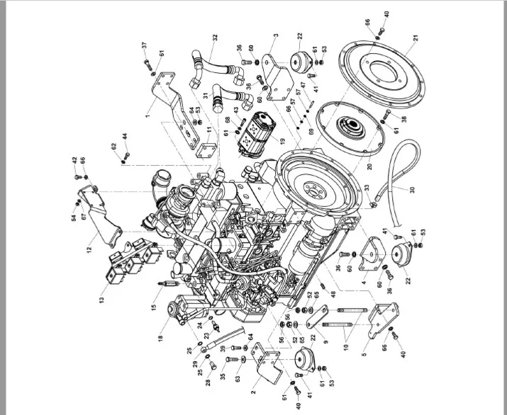
8. Removing the engine ………………………………………………………………………………………………..8-1
9. Removing the cooler …………………………………………………………………………………………………9-1
SECTION 35 – HYDRAULIC SYSTEM
10. Hydraulic system …………………………………………………………………………………………………….10-1
10.1. Hydraulic diagram ………………………………………………………………………………………………………………………….10-3
11. Hydraulics ………………………………………………………………………………………………………………..11-1
11.1. Removing the cooling hydromotor ……………………………………………………………………………………………………11-4
11.2. Removing the gear pump for steering ……………………………………………………………………………………………..11-8
11.3. Removing the tandem pumps for vibration and travel ……………………………………………………………………….11-14
11.3.1. Vibration pump ……………………………………………………………………………………………………………………………11-14
11.3.2. Travel pump ………………………………………………………………………………………………………………………………..11-16
11.4. Adjusting vibration frequency …………………………………………………………………………………………………………11-18
11.5. Adjusting pulse sensors ………………………………………………………………………………………………………………..11-19
11.6. Measuring hydraulic circuit safety pressures …………………………………………………………………………………..11-20
SECTION 39 – FRAMES
12. Articulated joint ……………………………………………………………………………………………………….12-1
12.1. Preparation work ……………………………………………………………………………………………………………………………12-4
12.2. Removing the steering joint …………………………………………………………………………………………………………..12-10
12.3. Removing the slewing ring bearing …………………………………………………………………………………………………12-15
12.4. Removing the steering joint bearing ……………………………………………………………………………………………….12-16
12.5. Installing the steering joint bearing …………………………………………………………………………………………………12-19
12.6. Adjusting the zero position of the steering joint ………………………………………………………………………………..12-22
13. Removing the hood …………………………………………………………………………………………………..13-1
SECTION 41 – STEERING
14. Steering cylinder ………………………………………………………………………………………………………14-1
14.1. Removing hydraulic cylinders for steering and CRAB …………………………………………………………………………14-4
14.2. Replacing packing material for steering or Crab hydraulic cylinders ……………………………………………………..14-5
SECTION 44 – AXLES AND WHEELS
15. Removing the drum ………………………………………………………………………………………………….15-1
15.1. Removing the vibration hydromotor ………………………………………………………………………………………………..15-12
15.2. Removing the travel hydromotor ……………………………………………………………………………………………………15-14
15.3. Removing the auxiliary transmission ………………………………………………………………………………………………15-16
15.4. Removing the front drum ………………………………………………………………………………………………………………15-18
15.5. Replacing the rubber mounting of the drum …………………………………………………………………………………….15-30
SECTION 50 – CAB CLIMATE CONTROL
16. Removing the heater/cooling air fans ………………………………………………………………………..16-1
16.1. Removing the heater ……………………………………………………………………………………………………………………..16-4
16.2. Removing cooling air fans ………………………………………………………………………………………………………………16-8
DV207 / DV207HF 3
TABLE OF CONTENTS
SECTION 55 – ELECTRICAL SYSTEM
17. Electrical installation ………………………………………………………………………………………………..17-1
17.1. Fuses …………………………………………………………………………………………………………………………………………..17-2
17.2. Storage battery ……………………………………………………………………………………………………………………………..17-4
17.3. Alternator ……………………………………………………………………………………………………………………………………..17-5
17.4. Starter Motor …………………………………………………………………………………………………………………………………17-7
17.5. Layout of wiring elements in the machine ………………………………………………………………………………………..17-10
18. Electrical system ……………………………………………………………………………………………………..18-1
18.1. Wiring diagram DV207 / DV207HF …………………………………………………………………………………………………..18-3
SECTION 90 – CAB
19. Cab ………………………………………………………………………………………………………………………….19-1
19.1. Idle and parking brake position sensor ……………………………………………………………………………………………..19-4
19.2. Left-hand control panel, reversing horn sensor ………………………………………………………………………………….19-4
19.3. Seat platform ………………………………………………………………………………………………………………………………..19-8
19.4. Power steering servo ……………………………………………………………………………………………………………………19-12
19.5. Seat switch …………………………………………………………………………………………………………………………………19-16
INDEX
IMAGES PREVIEW OF THE MANUAL:
CASE DV207 DV207HF VIBRATORY ROLLER SERVICE MANUAL PN 47508259 – PDF DOWNLOAD:
PLEASE NOTE:
- This is the same manual used by the dealers to diagnose and troubleshoot your vehicle
- You will be directed to the download page as soon as the purchase is completed. The whole payment and downloading process will take anywhere between 2-5 minutes
- Need any other service / repair / parts manual, please feel free to contact [email protected] . We still have 50,000 manuals unlisted
S.V