
Case Engine CNH 667TA Repair Manual 87600994 – PDF DOWNLOAD
Original price was: $95.95.$46.95Current price is: $46.95.
Case Engine CNH 667TA Repair Manual
Part No: 87600994
Description
Case Engine CNH 667TA Repair Manual
FILE DETAILS:
Case Engine CNH 667TA Repair Manual
Size : 9.9 MB
Format : PDF
Language : English
Number of Pages : 143 pages
Brand: Case
Type of machine: Engine CNH
Type of document: Repair Manual
Model: Case Engine 667TA
Part No: 87600994
DESCRIPTION:
Case Engine CNH 667TA Repair Manual
FOREWORD:
- A good diagnosis is carried out with the competence acquired from years of experience and taking part in repair courses. When a user complains about a bad efficiency or operating anomalies, his indications must be kept into due account, taking from them those useful information that will be used to guide our intervention. After having detected the anomaly, it is advisable to carry out failure search operations by decoding self
- Diagnosis data of the central electronic unit of theEDC (Engine Diesel Control) system. With the use of computerised tools, it is also possible to establish a bi–directional communication with the central unitwithwhich it is possible not only to decode the error codes, but also to address the image in its memory to obtain those further necessary information to go back to the anomaly origin. Every time an inconvenience occurs and its existence is detected,
- It is necessary to proceed with the electronic unit query through one of the pointed–out ways and then proceed with the diagnostic survey through tests and measures through which an outline of operating conditions is obtained and the real anomaly reasons are identified. In case the electronic unit does not provide indications, one will have to proceed with one’s experience by adopting traditional diagnostic modes.
- The exhaust gases can be partially conveyed back into the cylinders to lower themaximum values of the combustion temperature that are responsible for the production of nitrogen oxides (NOx). The exhaust gas recirculation system (EGR), lowering the combustion temperature by decreasing the concentration of oxygen in the combustion chamber, is therefore an effective system to control the emission of NOx.
- Internal EGR acting on the exhaust valves The internal EGR system, thanks to an appropriate exhaust cam design permits some of the exhaust gases to be reintroduced back into the engine cylinders. This type of EGR, internal EGR is not provided with any electronically controlled element: the system is always on. Its configuration doesn’t need any additional elements such as control valves, pipes or heat exchangers.
- The exhaust cam, besides themain lobe, has an additional lobe (C) compared to the configuration without EGR. During the intake stroke of the cylinder under examination, this lobe permits briefly opening the exhaust valve. In this way, recirculation is generated on the cylinder in the intake stroke due to the greater pressure of the exhaust gases compared to the intake gases.
CASE ENGINE CNH 667TA REPAIR MANUAL 87600994 – PDF DOWNLOAD:
IMAGES PREVIEW OF THE MANUAL:
TABLE OF CONTENTS:
Case Engine CNH 667TA Repair Manual
Coding of source engines EW–2–4
Main engines features EW–2–5
General engines features EW–2–6
Assembling play — specifications EW–2–8
Tightening torque EW–2–14
Tools EW–2–15
Graphic indications and symbols EW–2–16
667TA engines EW–2–17
Description of main mechanic
engine components EW–2–18
Crankcase EW–2–18
Drive shaft EW–2–19
Drive shaft seal rings EW–2–19
Connecting rods EW–2–20
Pistons EW–2–21
Distributing shaft EW–2–22
EGR exhaust gas recirculation system EW–2–22
Internal EGR acting on the
exhaust valves EW–2–22
Valve control EW–2–23
Cylinder head engines: 667TA/EBF —
667TA/EBD — 667TA/EED EW–2–24
Cylinder head engines: 667TA/EEG —
667TA/EEC EW–2–25
Valves and valve seats EW–2–26
Valves and valve seats EW–2–27
Valve drive jumpers EW–2–27
Engine head grinder EW–2–27
Engine flywheel EW–2–28
Auxiliary component drive EW–2–29
Engine lubrification EW–2–30
Heat exchanger EW–2–31
Oil pressure regulation valve EW–2–31
By–pass valve EW–2–31
Oil pump EW–2–32
Oil sump engines: 667TA/EEG –667TA/
EEC — 667TA/EBF — 667TA/EED EW–2–33
Oil sump engines: 667TA/EED —
667TA/EBD EW–2–34
Engine oil vapour recirculation EW–2–35
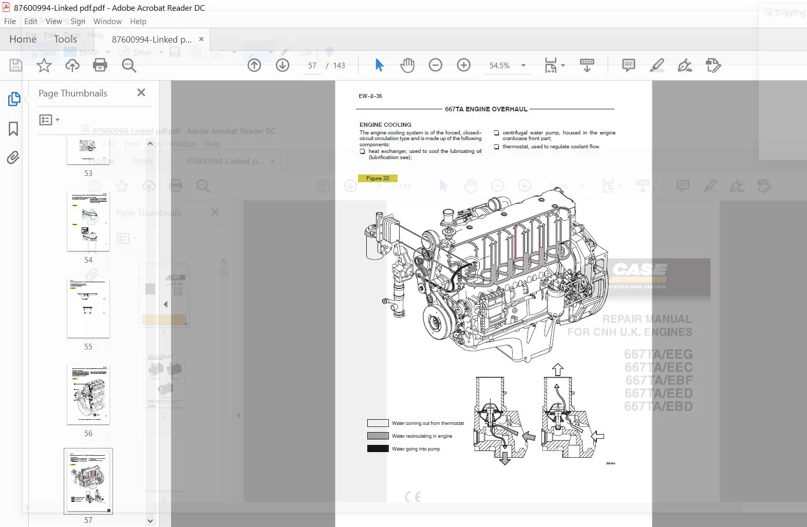
Engine cooling EW–2–36
Water pump EW–2–37
Thermostat EW–2–37
High pressure electronic injection
system (Common rail) EW–2–38
EDC 7 operation EW–2–39
Supply system EW–2–40
Supply system diagram EW–2–41
Fuel filter EW–2–42
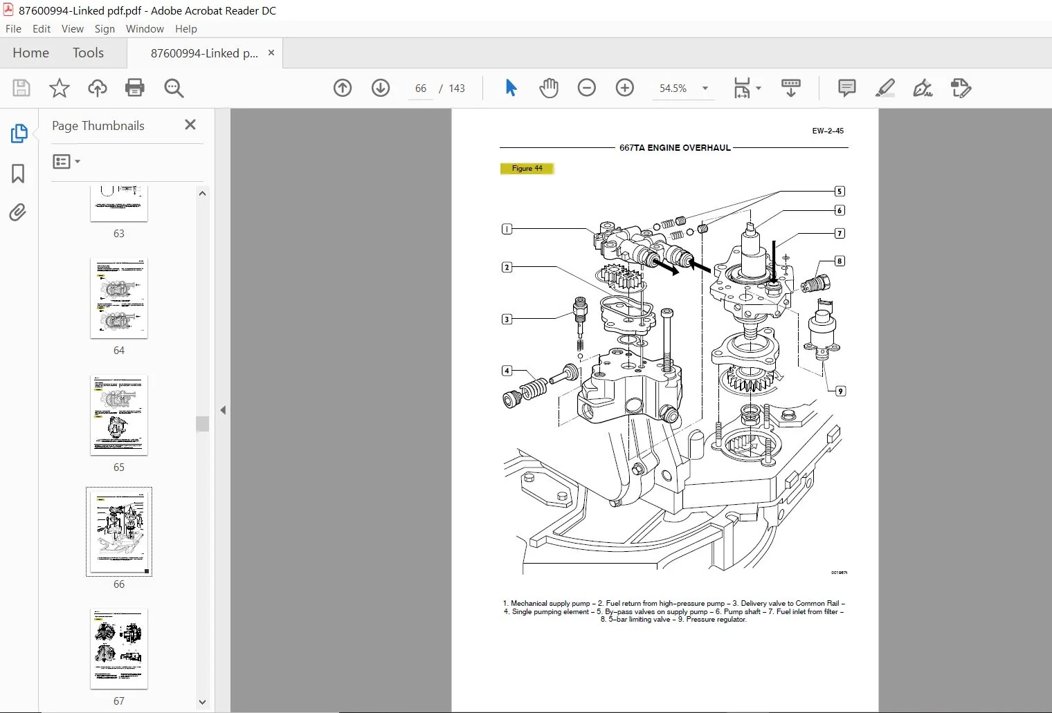
Mechanical supply pump EW–2–43
Normal operating condition EW–2–43
Output overpressure condition EW–2–43
Drain conditions EW–2–44
High–pressure pump type CP3 3 EW–2–44
High pressure pump–inside structure EW–2–46
Working principle EW–2–47
Operation EW–2–49
Rail EW–2–49
Boost gauge valve EW–2–50
Electro–injector EW–2–51
Electro–injector EW–2–52
Pressure limiter for fuel return EW–2–53
Location of the main electrical
components EW–2–54
EDC7 ECU EW–2–55
Cable on engine EW–2–56
Injectors connector (A) EW–2–57
Sensors connector (C) EW–2–57
Crankshaft sensor EW–2–58
Timing sensor EW–2–58
Supercharging air pressure —
temperature sensor EW–2–59
Engine oil temperature–pressure sensor EW–2–59
Fuel temperature and pressure sensor EW–2–60
Electro–injectors EW–2–61
Pre–post heating resistance
and contactor EW–2–62
Coolant temperature sensor EW–2–63
Fuel temperature sensor EW–2–64
High pressure pump — pressure regulator EW–2–65
Checking the fuel system EW–2–66
Description of tests and checks
that can be performed EW–2–66
Necessary equipment EW–2–66
Low pressure supply test EW–2–67
Low–Pressure Pump EW–2–68
Test on the pressure relief valve
on the rail EW–2–69
Test on fuel backflow from the return EW–2–70
Engines overhaul at the bench EW–2–72
Disassembling the engine EW–2–72
SECTION 2
Repair operations EW–2–81
Cylinder unit EW–2–81
Checks and measurements EW–2–81
Checking the eccentric lift and
the pin alignment EW–2–81
Bushings EW–2–81
Checking the surface supporting
the head on the cylinder cluster EW–2–83
Timing system EW–2–83
Distributing shaft EW–2–83
Replacing the bushings EW–2–84
Tappets EW–2–84
Mounting the tappets — Distributing shaft EW–2–84
Drive shaft EW–2–85
Measuring the journals and crankpins EW–2–85
Replacing the oil pump drive gears EW–2–87
Measuring the journal assembling play EW–2–87
Mounting the main bearings EW–2–87
Checking the drive shaft shoulder play EW–2–88
Connecting rod–piston assembly EW–2–88
Pistons EW–2–89
Measuring the piston diameter EW–2–89
Conditions for correct pin/piston
matching EW–2–90
Piston rings EW–2–90
Gudgeon pins EW–2–90
Connecting rods EW–2–91
Bushings EW–2–91
Checking the connecting rods EW–2–92
Checking the torsion EW–2–92
Checking the flexion EW–2–92
Mounting the connecting rod–piston
assembly EW–2–92
Connecting rod–piston coupling EW–2–92
Mounting the piston rings EW–2–93
Mounting the connecting rod/piston
assemblies in the cylinder liners EW–2–93
Measuring the crankpin assembling play EW–2–94
Checking piston protrusion EW–2–95
Distribution gearbox case EW–2–95
Valve timing EW–2–96
Flywheel cover case EW–2–96
Engine flywheel EW–2–97
Replacing the engine flywheel ring gear EW–2–97
Cylinder head EW–2–101
Removing the valves EW–2–101
Checking the cylinder head water seal EW–2–102
Checking the cylinder head supporting
surface EW–2–102
Valves EW–2–103
Valve descaling, check and grinding EW–2–103
Checking the play between
the valve stem, valve guide and
valve centring EW–2–103
Valve guide EW–2–103
Valves seats EW–2–104
Valve seat reconditioning — replacement EW–2–104
Valve springs EW–2–105
Mounting the cylinder head EW–2–106
Reattaching the cylinder head EW–2–106
Fitting injectors EW–2–107
Rods and tappets EW–2–108
Rocker arm assembly EW–2–108
Tappet clearance adjustment EW–2–109
Wiring support EW–2–111
PLEASE NOTE:
⦁ This is the same manual used by the DEALERSHIPS to SERVICE your vehicle.
⦁ The manual can be all yours – Once payment is complete, you will be taken to the download page from where you can download the manual. All in 2-5 minutes time!!
⦁ Need any other service / repair / parts manual, please feel free to contact us at heydownloadss @gmail.com . We may surprise you with a nice offer