CASE IH 750 Crawler Section E,H, I, 4MM Service Manual 9-72151A – 208 Pages
Original price was: $99.00.$24.95Current price is: $24.95.
CASE IH 750 Crawler Section E,H, I, 4MM Service Manual 9-72151A
Description
CASE IH 750 Crawler Section E,H, I, 4MM Service Manual 9-72151A – 208 Pages
CASE IH 750 CRAWLER SECTION E,H, I, 4MM SERVICE MANUAL 9-72151A – 208 PAGES:
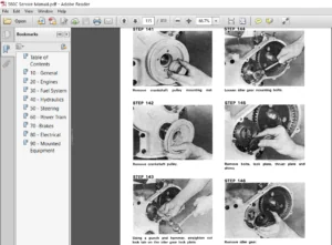
IMAGES PREVIEW OF THE MANUAL:
TABLE OF CONTENTS:
CASE IH 750 Crawler Section E,H, I, 4MM Service Manual 9-72151A
Case Crawler 750 Section E, H, I, 4MM Service Manual_9-72151A
Size : 615 MB
Format : PDF
Language : English
Number of Pages : 208 pages
Brand: Case
Type of machine: Crawler
Type of document: Service Manual
Model: Case Crawler 750 Section E, H, I, 4MM
Part No: 9-72151A
SERVICE SUGGESTIONS..............................................  3
SERVICING THE FUEL FILTERING SYSTEM.............................. 51
SERVICING THE•FUEL INJECTORS•FUEL INJECTION PUMP•CASE POWRCEL.... 67
SERVICING THE ASSEMBLIES CONTAINED IN THE ENGINE BLOCK...........115
DESCRIPTION:
CASE IH 750 Crawler Section E,H, I, 4MM Service Manual 9-72151A
TABLE OF CONTENTS
Engine Will Not Start
or is Difficult to Start —————————————— E-3 thru E-8
Lack of Power ——————————————————- E-9 thm E-21
Smoke From E~ne Exbaust —————————————- E-22 thruE-28
Excessive Fuel Consumption —————————————– E-29 tb.lru E-30
Excessive Oil Consumption ——————————————- E-31 thm E-36
Contamination in the Crankcase Oil ——————————— E-37 thru E-40
Engine Will Not Stop When
Fuel Is Shut ~ ———————————————————- E-40
Generator ———————————————————————-E-41
Starting Motor ————————————————— E-4. E-5 and E~41
Noise, Knocks and Vibration —————————————- E-42 thru E-47
Oil Leakage ——————————————————————- E-47
E-
TABLE OF CONTENTS
Case Four Cylinder A-30l Diesel Engine——- —- ——————— —– H-3
General Description – ———- ————————- – ———– H-4 fum H-5
Diesel Fuel Flow Diagrams ————————————————- H-6
Visual Inspection of the Fuel Lines —————————————– H- 7
Servictng Fuel Lines ——————————————————- H-8
Bleeding the Fuel System —————————— ——————— H-9
Fuel Tank Breather —– – —- – ———– ———————————- H- IO
Fuel Sediment Bowl ———————————- – – —- — – — H- IO thru H- ll
Fuel TankVVater Trap – – ———– – ———————— ————- — H- IO
Cleantngthe Fuel Tank ——– ——————– – ———– — ———– H-ll
Gum and Varnish in the Fuel ————————————— ——– H-12
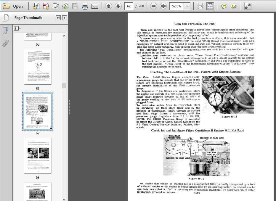
Checking the Conditions of the Fuel Filters VVith Engine Running — ——– H- 12
Checking 1st and 2nd Stage Filter Conditions If Engine Will Not start — — H- 12
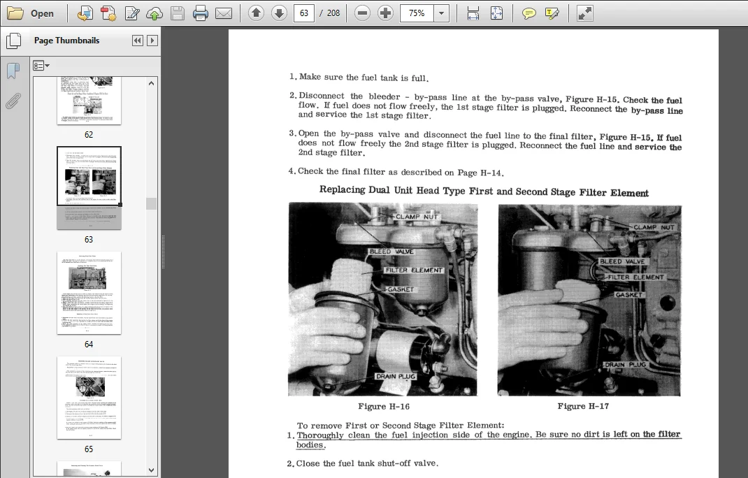
Replacing First and Second stage Filter Elements ———————– H- 13
Servicing Final Fuel Filter and Pressure Relief Valve – ——————– H-14
Checking Final Fuel Filter —————- ————- —————— H-14
Pressure Relief Valve ——- —– ————————————— H-15
Removing and Cleaning Pressure Relief Valve ————————— H-16
TABLE OF CONTENTS
FlJEL IN’J’ECTORS —————————————————– 1-5 thru 1- 25
Description and Operating PrincIples ——————————— 1-5 and 1-6
Diesel Tool Kits ————————————————————- 1-7
Checking Injector Operation on the Engine ———————————– 1-8
Removing and Installing Injector ——————————————– 1-8
Nozzle (Injector) Test Stand ———————————————— 1-10
Test Stand Installation —————————————————– 1-11
Test on Recommendations ————————————————- 1-12
Preparing Test Stand for Operation —————————————– 1-13
Testing Injector ————————————————— 1-13 thru 1-16
Setting Injector Opening Pressure ——————————————- 1-14
Disassembling, Cleaning, Checking and Reassembling Injector —– 1-17 thru 1-,25
ROBERT BOSCH MODEL PES MULTIPLE PLUNGER (EXTERNAL DRIVE)
FlJEL IN’J’ECTION PUMP —————————————————— 1-26
General Description and Important Precautions ——————— 1-26 and 1-27
Removing, T1m1ng and Replacing Fuel Injection Pump ————— 1-28 thruI-30
Adjusting the Governed Engine and Idle Speed ———————- 1-31 thru 1-35
Adjusting No Load (Low) Idle Speed and Engine Shut-off ——————– 1-36
CA.BE POWRCEL —————————————————– 1-41 thru 1-47
~neralDescription ——————————————————– 1-41
Servicing Powrcel ————————————————- 1-42 thru 1-47
Removing and Installing Powrcel ———————————- 1-43 thru 1-44
Cleaning and Checking Powrcel ———————————— 1-45 and 1-46
Instal1ing Powrcel Body Locating Pin ————————————— 1-47
1-
TABLE OF CONTENTS
ENGINE LUBRICATING SYSTEM ——————————- 4MM-4 thru 4MM-26
Engine Lubricating System Diagrams -4MM-4 thru 4MM-5 and 4MM-20 thru 4MM-21
Oil Pump Screen and Cover Removal————————————- 4MM-7
Adjusting Oil Pump Relief Valve Pressure ——————————- 4MM-9
Oil Filter ————————————————– 4MM-20 thru 4MM-23
Oil Cooler ————————————————————– 4MM-24
ENGINE COUNTER BALANCER ——————————- 4MM-I0 thru 4MM-19
Introduction ———————————————— 4MM-I0 thru4MM-ll
Balancer Removal and Disassembly ———————— 4MM-12 thru 4MM-13
Inspection of Oil Pump and Balancer ———————– 4MM-14 thru 4MM-15
Assembly of the Balancer ———————————- 4MM-16 thru 4MM-18
Installlng the Balancer in the Engine ———————————— 4MM-19
PISTONS, CONNECTING RODS AND CYLINDER SLEEVES —- 4MM-27 thru 4MM-54
Engine Run-In Procedure ———————————————- 4MM-28
~ons and Cylinder Sleeves —————————————— 4MM-29
Checking Compression Pressure ————————————– 4MM-30
~on and Connecting Rod Removal and Installation ——————- 4MM-32
Cy~er 5aeeves ——————————————————- 4MM-34
~~er Sleeve lIoning ———————————————— 4MM-36
~l1nder Sleeve Removal and Installation —————————— 4MM-37
~on ~ ———————————————————— 4l4M-38
Piston and Rings ——————————————————- 4MM-40
Measuring the Cylinder Sleeve —————————————– 4MM-42
Installing Replacement Piston Rings ———————– 4MM-43 thru 4MM-44
Connecting Rods and Bearing Liners ———————————– 4MM-45
Bearing Journal on Crankshaft —————————————– 4MM-46
Standard Bearing Liners ———————————————– 4MM-47
UnderSize Bearing Liners ———————————————- 4MM-48
Inspection of Connecting Rod Bearing Liners ————— 4MM-49 thru 4MM-51
~nd Piay————————————————————— 4Ml4-52
~on Pin Removal and Installation ———————————— 4MM-53
CRANKSIIAFT, MAIN BEARINGS AND FLYWHEEL ———— 4MM-55 thru 4MM-74
Crankshaft and Main Bearings ——————————————- 4MM-56
Removing and Insta.lling Main Bearing Liners ————————— 4MM-57
Checking Main Bearing on Clearance ———————————- 4MM-58
Inspection of Main Bearing Liners ————————– 4MM-59 thru 4MM-61
Crankshaft End Piay —————————————————- 4MM-62
Crankshaft Removal —————————————————- 4MM -63
Fl~heelltemoV3l —————————————————– 414M-64
Crankshaft and Oil Seal Removal ————————————– 4MM-64
Crankshaft ~eyFteDnoval ——————————————– 4MM-65
Timing Gear Cover Removal ——————————————- 4MM-65
Crankshaft and Crankshaft Gear Removal —————————— 4MM-66
UnderSize Main Bearing Liners ————————————— 4MM-68
4MM-
TABLE OF CONTENTS ( Continued)
Crankshaft I:nstallation ————————————————– 4MM-69
Installing Crankshaft Gear ———————————————- 4MM-70
I:nstalling Balancer Drive Gear on Crankshaft ————————— 4MM-71
I:nstalling New Crankshaft Rear on Seal ——————————– 4MM- 71
Installing Flywheel ———————— —————————– 4MM-72
Install1ng Ring Gear on Flywheel – – ————————————- 4MM-72
Installing Timing Gear Cover ——————————————- 4MM-73
Crankshaft Pulley Installation —————————————— 4MM-73
CAMSHAFT AND PUSH ROD LIFTERS ———————— 4MM-75 tb.ru 4MM-82
Camshaft Removal and Installation ————————————– 4MM-76
Inspecting Caxnshaft lJushings ——————————————- 4MM-77
Camshaft Bushing Removal and Installation —————————– 4MM-78
Camshaft Gear Removal and Installation ——————————– 4MM-80
Push Rods and Lifters ————————————————– 4MM-82
FUEL INJECTION PUMP DRIVE AND TIMING GEAR TRAIN — 4MM-83 tb.ru 4MM-91
Fuel Inj ection Pump Drive ———————————————– 4MM-84
Injection Pump Drive Removal —————————————— 4MM-85
Injection Pump Drive Inspection —————————————– 4MM-87
Injection Pump Drive Gear Removal and Installation ——————— 4MM-87
TIMING GEAR TRAIN —————————————– 4MM-88 tb.ru 4MM-91
Checking Timing Gear Backlash —————————————– 4MM-B9
Checking Timing Pointer Accuracy ————————————- 4MM-90
PLEASE NOTE:
- This is the SAME manual used by the dealers to troubleshoot any faults in your vehicle. This can be yours in 2 minutes after the payment is made.
- Contact us at [email protected] should you have any queries before your purchase or that you need any other service / repair / parts operators manual.