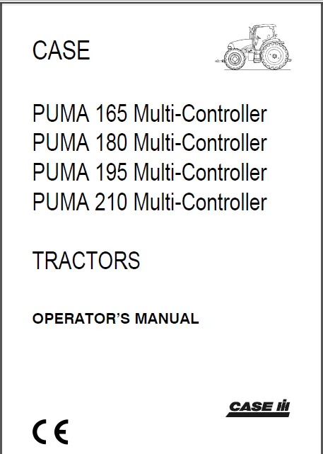
Case IH PUMA 165 180 195 210 Multi Controller Tractors Operators Manual – PDF DOWNLOAD
Original price was: $60.95.$30.95Current price is: $30.95.
Case IH PUMA 165 180 195 210 Multi Controller Tractors Operators Manual
Description
Case IH PUMA 165 180 195 210 Multi Controller Tractors Operators Manual
DESCRIPTION:
- This Manual has been prepared to assist you in the correct procedure for running-in, driving and operating your new tractor and how to maintain it. Read this Manual carefully. Your tractor is intended for use in normal and customary agricultural applications. If at any time you require advice concerning your tractor, do not hesitate to contact your authorised dealer.
- The dealer has factory trained personnel, genuine manufacturers’ parts and the necessary equipment to carry out all your service requirements.
- Your tractor has been designed and built to give maximum performance, economy and ease of operation under a wide variety of operating conditions. Prior to delivery, the tractor was carefully inspected, both at the factory and by your dealer to ensure that it reaches you in optimum condition.
- To maintain this condition and ensure trouble-free operation, it is important that the routine services, as specified in Section 4 of this Manual, are carried out at the recommended intervals.
- OPERATOR’S MANUAL STORAGE A storage pocket for the Operator’s Manual can be found on the rear of the seat. The manual should be kept to hand in this pocket at all times.
- CLEANING THE TRACTOR Your tractor is a state-of-the-art machine with sophisticated electronic controls. This should be borne in mind when cleaning the tractor, particularly if using a high pressure washer. Even though every precaution has been taken to safeguard electronic components and connections, the pressure generated by some of these machines is such that complete protection against water ingress cannot be guaranteed. When using a high pressure washer, do not stand too close to the tractor and avoid directing the jet at electronic components, electrical connections, breathers, seals, filler caps, etc. Never direct a cold water jet at a hot engine or exhaust.
- SAFETY Pages 1-7 to 1-13 inclusive list the precautions to be observed to ensure your safety and the safety of others. Read the safety precautions and observe the advice given beforeoperating the tractor.
- SERVICE AFTER FIRST 50 HOURS WORK In Section 9, at the back of this Manual, you will find the 50-hour service reports. After you have operated the tractor for 50 hours, take your tractor, together with this Manual, to your dealer. He will then perform the manufacturer’s recommended 50 hour service and complete the service report sheets (pages 9-1 and 9-3). The first sheet (page 9-1) is the dealer’s copy and should be removed by the dealer after the service has been carried out. The second page (page 9-3) is your copy of the service performed. Ensure that you and the dealer sign both copies.
- SERVICE PARTS It should be pointed out that genuine parts have been examined and approved by the Company. The installation and/or use of “non-genuine” products could have negative effects upon the design characteristics of your tractor and thereby affect its safety. CASE IH is not liable for any damage caused by the use of “non-genuine” parts and accessories. Only genuine Case IH replacement parts should be used.
- The use of non-genuine parts may invalidate legal approvals associated with this product. It is prohibited to carry out any modifications to the tractor unless specifically authorised, in writing, by the After Sales Service department of the CASE IH.
- WARRANTY Your tractor is warranted according to legal regulations in your country and the contractual agreement with the selling dealer. No warranty shall, however, apply if the tractor has not been used, adjusted and maintained according to the instructions given in the Operator’s Manual.
IMAGES:
CASE IH PUMA 165 180 195 210 MULTI CONTROLLER TRACTORS OPERATORS MANUAL – PDF DOWNLOAD:
TABLE OF CONTENTS:
GENERAL INFORMATION AND SAFETY
TO THE OWNER 1-1
END USER LICENCE AGREEMENT TERMS 1-2
PRODUCT IDENTIFICATION 1-3
ECOLOGY AND THE ENVIRONMENT 1-6
SAFETY INFORMATION 1-7
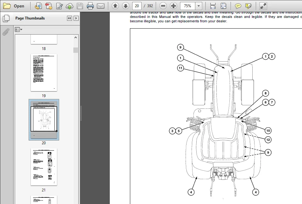
SAFETY DECALS 1-14
INTERNATIONAL SYMBOLS 1-19
AIRBORNE NOISE EMISSION 1-20
SECTION 2
LAYOUT AND FUNCTION OF THE CONTROLS AND INSTRUMENTS
CAB 2-4
ELECTRICAL POWER PANEL 2-20
DRIVER’S SEAT 2-23
PARKING BRAKE, THROTTLE AND FOOT PEDALS 2-31
CONTROL ELEMENTS ON THE STEERING COLUMN 2-33
INTEGRATED CONTROL UNIT (ICU) 2-36
POWERSHIFT TRANSMISSION SYSTEM 2-76
DIFFERENTIAL LOCK 2-97
FOUR WHEEL DRIVE 2-99
FRONT AXLE SUSPENSION (where fitted) 2-101
SECTION 3
WORKING WITH THE TRACTOR
IMPORTANT NOTES 3-2
CONNECTING JUMP LEADS TO THE BATTERY 3-4
STARTING THE ENGINE 3-5
STOPPING THE ENGINE 3-8
POWER MANAGEMENT (PM) 3-10
CONSTANT ENGINE SPEED 3-11
HEADLAND MANAGEMENT CONTROL (HMC) 3-13
TURN ASSIST (WHERE FITTED) 3-24
REAR PTO 3-26
FRONT PTO AND THREE-POINT HITCH (where fitted) 3-40
ELECTRONIC DRAFT CONTROL (EDC) 3-56
ELECTRO HYDRAULIC REMOTES 3-68
THREE-POINT HITCH 3-86
QUICK HITCH 3-92
LINKAGE STABILISERS 3-94
DRAWBARS AND TOWING ATTACHMENTS 3-99
TRAILER BRAKING SYSTEMS (where fitted) 3-112
WHEEL TRACKS 3-119
BALLASTING AND TYRES 3-134
TABLE OF CONTENTS
SECTION 4
LUBRICATION AND MAINTENANCE
GENERAL INFORMATION 4-1
PROTECTIVE GUARDS 4-5
LUBRICATION AND MAINTENANCE CHART 4-10
WHEN THE WARNING SYMBOL APPEARS 4-11
EVERY 10 HOURS OF OPERATION OR DAILY 4-14
EVERY 50 HOURS 4-17
EVERY 100 HOURS 4-28
EVERY 300 HOURS 4-29
EVERY 600 HOURS 4-33
EVERY 1200 HOURS OR 12 MONTHS 4-40
EVERY 1200 HOURS OR 2 YEARS 4-46
EVERY 3 YEARS 4-54
GENERAL MAINTENANCE 4-55
STORING THE TRACTOR 4-73
SECTION 5
FAULT FINDING
INTRODUCTION 5-1
ENGINE 5-4
TRANSMISSION 5-7
HYDRAULICS 5-8
THREE-POINT HITCH 5-9
BRAKES 5-10
CAB 5-10
ELECTRICAL SYSTEM 5-11
SECTION 6
ACCESSORIES
AFS 200 MONITOR (where fitted) 6-2
COOLANT IMMERSION HEATER 6-3
TRANSMISSION OIL HEATER 6-3
ROTATING BEACON 6-4
AUXILIARY HEADLIGHTS 6-4
ADDITIONAL 40 AMP SOCKET 6-5
BATTERY ISOLATOR SWITCH 6-6
DYNAMIC FRONT FENDERS 6-7
SECTION 7
SPECIFICATIONS
GENERAL DIMENSIONS ALL MODELS 7-2
VEHICLE WEIGHTS 7-5
CAPACITIES 7-6
ENGINE 7-7
FUEL SYSTEM 7-7
COOLING SYSTEM 7-8
TRANSMISSION 7-8
MAXIMUM OPERATING ANGLE 7-9
REAR POWER TAKE OFF 7-9
FRONT POWER TAKE OFF 7-9
HYDRAULIC SYSTEM 7-10
REMOTE CONTROL VALVES 7-14
FRONT 3-POINT HITCH 7-14
BRAKES 7-15
STEERING 7-15
ELECTRICAL EQUIPMENT 7-16
MINIMUM HARDWARE TIGHTENING TORQUES 7-17
MINIMUM HARDWARE TIGHTENING TORQUES 7-18
SECTION 8
FIRST SERVICE SHEETS
SECTION 9
INDEX DETAIL
INDEX
Numerics
4 wheel drive
Safety Precautions 2-100
A Accessory
40A power socket 6-5
AFS 200 Monitor 6-2
Auxiliary Headlights 6-4
Battery Isolator Switch 6-6
Dynamic Front Fenders 6-7
Engine Coolant Immersion Heater 6-3
Rotary beacon 6-4
Transmission Oil Heater 6-3
Acoustic alarms 2-67
Air conditioning control 2-11
Airborne noise emission 1-20
Alarm functions 2-67
Audible beep 2-48
Automatic Engine Shutdown 2-50, 3-8
Automatic temperature control 2-13
B
Backlight adjustment 2-49
Ballasting 3-134
Before Operating 2-1
Brake Pedals 2-32
C
Cab 2-4
Cab Identification 1-5
Cab Pressurisation Monitor 2-16
Carrying the tractor on a transporter 3-3
Cleaning the tractor 1-1
Clutch Pedal 2-77
Clutch pedal 2-31
Cold starting aid 3-6
Connecting Jump Leads 3-4
Constant Engine Speed (CES) 3-11
Controls in the Driver’s Cab 2-2
Coolant temperature gauge 2-36
D
Decals 1-14
Differential lock 2-97
Operating in Automatic Mode 2-98
Operating in Manual Mode 2-97
Digital Clock 2-40, 2-45
Dot matrix display 2-41
Driveline Identification 1-4
Driver’s seat 2-23
Dual rear wheels 3-132
E
Ecology and the environment 1-6
Electrical Power Sockets 2-20
Electronic Draft Control 3-56
Console 3-57
Draft control 3-61
EDC control panel 3-57
External switch 3-66
Hitch Position Display 3-58
Indicator light panel 3-58
Position Control 3-64
Pre-operation settings 3-60
Ride control 3-65
Electronic Remote Valves 3-68
End user licence agreement terms 1-2
Engine function displays 2-40
Engine number 1-4
Engine oil pressure gauge 2-36
Error codes and Warnings 2-68
External Rear View Mirrors 2-8
FF
ault Finding
Brakes Features 5-10
Cab Features 5-10
Electrical system 5-11
Engine 5-4
Hydraulic Systems 5-8
Three-point Hitch 5-9
Transmission Features 5-7
First service after 50 hours work 1-1
Follow You Home Lights 2-34
Foot Brake 2-32
Foot Throttle Pedal 2-31
Four wheel drive 2-99
Operating 4WD in Manual Mode 2-99
Operating in Automatic Mode 2-99
Front Axle Suspension 2-101
Front hitch 3-45
Coupling Implement to 3-54
EXTERNAL CONTROLS 3-51
Hitch Settings and Adjustments 3-53
Operating mode 3-50
Operation 3-46
Setting the Height 3-46
Uncoupling Implement from Tractor 3-55
Front PTO 3-40
Auto PTO function 3-42
PTO Switch Operation 3-41
Fuel Level Gauge 2-36
GG
eneral information 1-1
Ground speed 2-93
Ground speed display 2-40
H
Hand throttle 2-32
Hazard light switch 2-35
Headland Management Control (HMC) 3-13
Function 3-15
Playing a Programme 3-20
9 – 2
SECTION 9 – INDEX
Quick Guide 3-13
Recording a programme 3-18
Symbols 3-17
Hitch
Ball hitch 3-109
Fixed Tow Pin (Piton) 3-108
Swivelling Tow Pin – Auto Engagement 3-107
Swivelling Tow Pin – Manual
Engagement 3-107
Vertically adjustable, with non-swivelling
tow hitch 3-105
Vertically adjustable, with swivelling tow
hitch 3-106
I
ICU 2-36
Implement Monitor Installation 2-18
In cab storage 2-19
International symbols 1-19
K
Key Pad 2-42
Key-start switch 2-33, 3-6
L
Lift Rods, Lower Links and Top Link 3-88
Linkage Stabilisers 3-94
Lubrication and maintenance
50-hour service 4-2
Air conditioning system maintenance 4-54
Automatic pick-up hitch 4-59
Battery electrolyte check 4-44
Battery electrolyte level 4-29
Bulb replacement 4-62
Cab Suspension Adjustment 4-60
Change 4WD differential oil 4-42
Change 4WD planetary hub oil 4-43
Change air brake drier reservoir 4-53
Change cab air filters 4-40
Change engine air cleaner inner element 4-50
Change engine breather filter 4-52
Change front PTO gearbox oil 4-43
Change fuel filters 4-38
Change hydraulic and transmission
oil filters 4-35
Change the engine air cleaner
outer element 4-36
Change transmission/rear axle/hydraulic
oil and filters 4-41
Check brake pedal latching/unlatching 4-58
Check engine air intake connections 4-37
Check Front PTO Gearbox Oil Level 4-32
Check remote control valve drain bottles 4-59
Check transmission/rear axle
and hydraulic oil level 4-31
Check valve tappet clearance 4-51
Check wheel nuts 4-26
Clean the cab air filters 4-18
Cleaning the radiator, intercooler, oil cooler
and air-conditioner condenser 4-17
Cleaning the tractor 4-71
Drain air brake reservoir 4-16
Draining and Refilling the Cooling System 4-46
Draining the water separator 4-13
Drive belt tension 4-28
Engine oil change 4-33
Engine oil level 4-15
Four wheel drive lubrication 4-39
Fuel specifications 4-3
Fuel system bleeding 4-55
Fuses and relays 4-65
General Information 4-1
Hand brake adjustment 4-32
Headlight and worklamp adjustment 4-61
Inspect poly V-belt 4-30
Lubricants and Coolants 4-8
Lubricate all grease fittings 4-20
Lubrication and maintenance chart 4-10
Outer element 4-11
Protecting the electrical/electronic components
during charging or welding 4-72
Radiator Coolant Level 4-14
Reservoir 4-16
Safety covers and guards 4-5
Tractor storage 4-73
Transmission clutch calibration 4-56
Tyre Pressures 4-27
M
Mobile telephone 2-18
Multi-function switch 2-34
PP
erformance monitor 2-60
Power Beyond Couplings 3-84
Power Beyond Ports 3-83
Power Management (PM) 3-10
Powershift Transmission 2-76
“Go To” mode 2-83, 2-87
Changing gear shift threshold 2-86
Changing the Auto Shift Point 2-84
Changing the Gear Span 2-85
Creeper Gears 2-91
Error Codes 2-92
Operation 2-77
Speed matching 2-88
Transmission calibration 2-92
Product identification 1-3
PTO operation 1-10
QQ
uick-fit couplers 3-92
R
Radio 2-17
Rear PTO 3-26
Attaching PTO-driven equipment 3-28
Auto PTO Control 3-36
Description 3-26
External switch 3-38
9 – 3
SECTION 9 – INDEX
PTO Switch Operation 3-27
Two-speed PTO systems 3-30
Two-speed PTO with changeable
stub shaft 3-31
Two-speed shiftable PTO 3-33
remote valves 3-68
Einstellung der Durchflussmenge 3-69
Operating Continuous Flow Hydraulic
Equipment 3-81
Operating Several Remote Valves
Simultaneously or Remote
Valves and Hydraulic Lift 3-82
Operation 3-71
Replaying a Timed Programme 3-79
Zeiteinstellung 3-69
Rollover protection 1-13
S
Screen wash/wipe control 2-35
Service Parts 1-1
Servicing the tractor 1-11
Specifications
Brake 7-15
Capacities 7-6
Cooling System 7-8
Electrical Equipment 7-16
Engine 7-7
Front 3-point hitch 7-14
Front PTO 7-9
Fuel System 7-7
General Dimensions 7-2
Hydraulic Systems 7-10
Minimum Hardware Tightening Torques 7-17
Operating Angle 7-9
Rear PTO 7-9
Remote Control Valves 7-14
Steering 7-15
Transmission Features 7-8
Vehicle Weights 7-5
Speed display 2-47
Starting the Engine 3-7
Steering Column Adjustment 2-33
Stopping the Engine 3-8
Swinging Drawbar 3-99
T
Three-point Hitch 3-86
Top link and right-hand lift rod 3-90
Electronic Operation 3-90
Top link support bracket 3-91
Towing equipment 3-104
Towing the Tractor 3-3
Tractor Identification 1-3
TRAILER BRAKE SYSTEM 3-112
AIR OPERATED Trailer Braking System
(Italy only) 3-117
Dual Line System 3-116
Hydraulic 3-113
Pneumatic 3-114
Single Line System 3-116
Transport Locks 3-52
Turn assist 3-24
VV
ehicle identification plate 1-3
Vehicle weight information 1-5
WW
arning lights and telltales 2-37
Warranty 1-1
Wheel tracks 3-119
Bar axle 3-126
Front axle oscillation stops 3-122
Front wheel alignment 3-123
Front Wheel Track Adjustment 3-119
Rear wheel track adjustment 3-124
Steering Stops 3-122
Working with the tractor 1-9
NOTE: CNH Österreich GmbH retains the right to modify
the technical data at any time to differ from the present text
and to make constructive improvements to the current
versions of the pictures and diagrams in this manual without
thereby entering into a commitment to retrofit machines sold
prior
All details in this manual are based on the status of the technical
data at the time of printing
Reprints and translations, including partial reprints and
translations, are prohibited without the written approval of
CNH Österreich GmbH
FILE DETAILS:
Brand: Case IH
Model: 165, 180, 195, 210, 225, Puma 165, Puma 180, Puma 195, Puma 210, Puma 225 PUMA 165, 180, 195, 210, 225, Tractors Agricultural Operator`s Manual
Format: PDF
Product line: Tractors
Publication type: Operator’s Manual
PLEASE NOTE:
⦁ This is not a physical manual but a digital manual – meaning no physical copy will be couriered to you. The manual can be yours in the next 2 mins as once you make the payment, you will be directed to the download page IMMEDIATELY.
⦁ This is the same manual used by the dealers inorder to diagnose your vehicle of its faults.
⦁ Require some other service manual or have any queries: please WRITE to us at [email protected]