Case IH Tractor Axial Flow 5088,6088,7088 Combine Complete Service Manual (84242798) – PDF Download
Original price was: $59.95.$39.95Current price is: $39.95.
Case IH Tractor Axial Flow 5088,6088,7088 Combine Complete Service Manual 84242798
Description
Case IH Tractor Axial Flow 5088,6088,7088 Combine Complete Service Manual 84242798
FILE DETAILS:
Case IH Tractor Axial Flow 5088,6088,7088 Combine Complete Service Manual_84242798
Size : 135 MB
Format : PDF
Language : English
Number of Pages : 798 pages
Brand: Case IH
Type of machine: Tractor
SAMPLE PAGE FROM THE MANUAL:
STARTER SYSTEM TROUBLESHOOTING:
Before continuing with starter system troubleshooting make sure the starting system checklist has been followed. Also, confirm starting system power distribution is good
.Key switch OFF, there must be B+ power at:
– Starter solenoid B+ stud (on starter motor assembly)
– Starter relay B+ stud
– Ignition switch terminal #1
STEERING RELIEF VALVE
- If the steering wheels are turned to their stops, or the wheels can no longer be turned, the steering system pressure increases until it goes on relief. When the steering relief opens it will limit the amount of pressure that may be exerted on the spring end of the steering priority spool (6). This will let the PFC high-pressure standby force the spool against the spring, diverting excess pump flow to the hydraulic circuits. When the signal pressure increases above 185 bar (2680 psi), a simple relief valve (7) located in the main valve block signal line will open.
- An office (10) (in the hand pump) is located in the circuit to limit the amount of oil that is being fed into the signal line, so that the relief valve can limit the pressure in the signal line. This will limit the signal pressure available to the steering priority valve and the compensator. The purpose of this relief valve is to limit the maximum pressure available to the spring-side of the priority spool, thus allowing oil to flow to the main valve assembly. If the steering relief pressure is set too close to the high-pressure stand-by pressure, the oil flow to the main valve assembly may be cut off when the steering relief valve opens.
MANUAL STEERING
- The steering circuit will permit manual steering control of the combine in the event of a dead engine; however, steering effort is more demanding. Manual steering uses the existing oil in the steering circuit for the oil supply, and the operator turning the steering wheel as input power. In manual steering operation, the metering section (turned by the operator) is used as the pump to supply oil to the steering cylinder. As the operator rotates the steering wheel, the centering springs compress and the main spool changes relationship to the sleeve.
- Since there is no supply of hydraulic oil from the PFC pump, the inlet check valve will be held on its seat by the spring. At this point, the recirculation check ball will not be seated due to the fact there is no incoming oil. This allows oil from the return port to be drawn past the recirculation check, through the main spool and sleeve, to supply the metering section, which is now acting as the pump. The metering section controls the amount of oil being directed to the cylinder based on the rotation speed of the steering wheel. Oil flow from the metering section is then directed to the spool and sleeve, then out to the steering cylinder.
TABLE OF CONTENTS:
Case IH Tractor Axial Flow 5088,6088,7088 Combine Complete Service Manual 84242798
ELECTRICAL SCHEMATIC POSTER – PRIOR TO PIN Y8G000101 87719035
ELECTRICAL SCHEMATIC POSTER – PIN Y8G000101 AND AFTER 87474621
HYDRAULIC SCHEMATIC POSTER – PRIOR TO PIN Y8G000101 87719034
HYDRAULIC SCHEMATIC POSTER – PIN Y8G000101 AND AFTER 87474623
STANDARD TORQUE SPECIFICATIONS SECTION 1001
TORQUE SPECIFICATIONS – DECIMAL HARDWARE 1001-2
TORQUE SPECIFICATIONS – METRIC HARDWARE 1001-3
TORQUE SPECIFICATIONS – STEEL HYDRAULIC FITTINGS 1001-4
LOCTITE CHART 1001-5
STATIONARY AIR SCREEN SECTION 2004
Nozzle Drive Motor 2004-3
Removal 2004-3
Installation 2004-5
Vacuum Fan and Rotating Arm 2004-7
Removal 2004-7
Installation 2004- 0
ENGINE REMOVAL SECTION 2020
SPECIFICATIONS 2020-2
SPECIAL TORQUES 2020-2
SPECIAL TOOLS 2020-2
ENGINE REMOVAL 2020-3
ENGINE INSTALLATION 2020-17
ELECTRICAL SCHEMATICS SECTION 4001
SCHEMATIC COLOR LEGEND 4001-2
SUBSYSTEM INDEX 4001-4
ACTUATORS 4001-6
POWER DISTRIBUTION 4001-8
STARTING AND CHARGING SYSTEM 4001-9
CHASSIS GROUNDS 4001-10
CHASSIS GROUNDING POINT LOCATIONS 4001-11
CLEAN GROUNDS 4001-12
POWER DISTRIBUTION (FUSE BLOCKS) 4001-13
UNLOADER CONTROL 4001-16
GRAIN TANK COVERS CONTROL 4001-17
CHAFFER SPREADER CONTROL 4001-18
BACKUP ALARM 4001-19
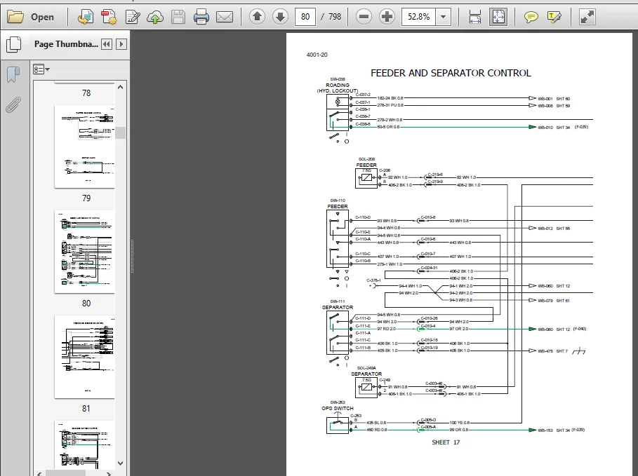
FEEDER AND SEPARATOR CONTROL 4001-20
SPREADER PATTERN CONTROL 4001-22
HEADER SELECTOR VALVE/DECK PLATE CONTROL 4001-23
CONCAVE CONTROL WITH PRESET MACHINES 4001-24
FAN CONTROL WITH PRESET MACHINES 4001-26
ROTOR CONTROL WITH PRESET MACHINES 4001-28
SIEVE CONTROL 4001-30
MULTIFUNCTION PROPULSION HANDLE 4001-34
SIDE KNIVES (CAB) 4001-35
HEADER REEL CONTROL 4001-36
HEADER HEIGHT/TILT CONTROL CAB 4001-38
HEADER HEIGHT/TILT CONTROL CHASSIS 4001-40
SPEED MONITOR 4001-44
A-POST INSTRUMENTATION 4001-46
GRAIN SCAN MONITOR 4001-48
RADIO 4001-49
WIPERS 4001-49
AUXILIARY POWER / HORN / DOME LIGHTS 4001-50
POWER GUIDE AXLE / VARIABLE PROPULSION 4001-51
LUBE SYSTEM 4001-52
RIDE CONTROL 4001-52
ENGINE AND THROTTLE CONTROL/GRID HEATER 4001-53
ENGINE CONTROL 4001-54
HVAC / CAB PRESSURE / AIR SEAT 4001-56
AUTO GUIDANCE 4001-58
PRECISION FARMING 4001-61
BACKLIGHTING / POWER 4001-62
BACKLIGHTING / GROUNDS 4001-63
SIEVE LIGHT & UNDERPANEL LIGHT 4001-64
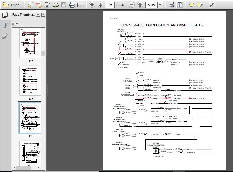
TURN SIGNALS, TAIL/POSITION, AND BRAKE LIGHTS 4001-66
PARKING BRAKE CONTROL 4001-71
BEACON LIGHTS 4001-72
EUROPEAN HEADLIGHTS/BEACON LIGHTS 4001-73
FRONT ROOF WORK LIGHTS 4001-74
REAR, SIDE AND HEADER WORK LIGHTS 4001-76
CAN BUS AND RS232 SYSTEM 4001-78
ELECTRICAL SYSTEM SECTION 4003
SPECIAL TOOLS 4003-3
INSTRUMENTATION AND CONTROLS 4003-4
FUSE AND RELAY IDENTIFICATION 4003-8
CAB CONNECTOR AND COMPONENT LOCATIONS 4003-12
GRAIN MOISTURE/BYPASS UNIT CONNECTOR LOCATIONS 4003-20
ROTOR SPEED CONTROL CONNECTOR LOCATIONS 4003-21
ENGINE COMPARTMENT CONNECTOR LOCATIONS 4003-22
BRAKE SWITCH CONNECTOR LOCATIONS 4003-24
MACHINE GROUND LOCATIONS 4003-25
GROUND POINT LOCATIONS 4003-26
COMBINE SENSOR LOCATIONS 4003-33
COMBINE SENSOR TESTING 4003-44
ELECTRICAL CONNECTORS PINOUT INFORMATION 4003-51
CAN TERMINATOR LOCATIONS 4003-93
STARTING SYSTEM CHECKLIST 4003-95
STARTING SYSTEM POWER DISTRIBUTION 4003-95
STARTER SYSTEM TROUBLESHOOTING 4003-96
STEERING CYLINDER SECTION 5030
SPECIAL TORQUES 5030-2
STEERING CYLINDER 5030-3
Removal 5030-3
Installation 5030-5
STEERING AXLE SECTION 5040
Wheel Bearings 5040-3
DIsassembly 5040-3
Assembly 5040-5
Servicing the Steering Tie Rod End 5040-6
Removal 5040-6
Installation 5040-8
Toe in Adjustment 5040-9
Steering Axle Assembly 5040-11
Axle Extension Positions 5040-12
Height Positions 5040-12
Width Positions 5040-13
Center Section 5040-14
Removal 5040-14
Installation 5040-18
Steering Knuckle 5040-22
Disassembly 5040-23
Assembly 5040-23
Bushing Replacement 5040-24
Removal 5040-24
Installation 5040-25
POWER GUIDE AXLE SECTION 5054
Motor Removal 5054-3
Power Guide Axle – Exploded View 5054-4
Motor Installation 5054-5
HYDROSTATIC DRIVE PUMP SECTION 6017
Removal 6017-3
Inspection 6017-7
Installation 6017-7
PROPULSION SYSTEM AIR REMOVAL 6017-11
Combines without Power Guide Wheels 6017-11
Combines with Power Guide Wheels 6017-12
HYDROSTATIC MOTOR SECTION 6035
Removal 6035-3
Illustration of One Speed and Two Speed Hydrostatic Motors 6035-4
Installation 6035-5
TRANSMISSION REMOVAL AND INSTALLATION 6035-7
ILLUSTRATION OF TRANSMISSION REMOVAL 6035-9
Installation 6035-10
GEAR SHIFT CONTROL CABLE ADJUSTMENT 6035-12
PROPULSION SYSTEM AIR REMOVAL 6035-13
Combines without Power Guide Wheels 6035-13
Combines with Power Guide Wheels 6035-14
BRAKE ASSEMBLY AND TRANSMISSION COVER REMOVAL SECTION 6040
SPECIFICATIONS 6040-3
SPECIAL TORQUES 6040-3
SPECIAL TOOLS 6040-3
BRAKE ASSEMBLY AND TRANSMISSION COVER REMOVAL 6040-5
SHIFTER RAILS AND SHIFT FORK REMOVAL 6040-7
INPUT HOUSING AND SHAFT REMOVAL 6040-10
CHANGE GEAR SHAFT REMOVAL AND DISASSEMBLY 6040-13
DIFFERENTIAL REMOVAL AND DISASSEMBLY 6040-16
DIFFERENTIAL PINION SHAFT REMOVAL AND DISASSEMBLY 6040-21
DIFFERENTIAL PINION SHAFT ASSEMBLY AND INSTALLATION 6040-27
Setting The Differential Pinion Shaft End Play 6040-34
DIFFERENTIAL ASSEMBLY AND INSTALLATION 6040-36
Measuring the Shim Thickness for Differential Bearing Cap 6040-40
CHANGE GEAR SHAFT ASSEMBLY 6040-43
INPUT HOUSING AND SHAFT ASSEMBLY 6040-45
CHANGE GEAR SHAFT AND INPUT HOUSING INSTALLATION 6040-47
Setting the Change Gear Shaft End Play 6040-49
Measuring the Internal Spline Shaft Wear 6040-51
SHIFTER RAILS AND SHIFT FORK ASSEMBLY 6040-53
TRANSMISSION COVER AND BRAKE INSTALLATION 6040-57
CROSS-SECTIONAL DRAWING OF TRANSMISSION 6040-60
FINAL DRIVE SERVICE SECTION 6060
SPECIFICATIONS 6060-2
SPECIAL TOOLS 6060-2
FINAL DRIVE SERVICE 6060-3
CROSS-SECTIONAL DRAWING OF FINAL DRIVE 6060-23
PTO GEARBOX SECTION 6065
Section 6065 is in Book 4 of this Service Manual It was issued with the first revision of this manual
PTO HOUSING SERVICE SECTION 6071
SPECIFICATIONS 6071-2
SPECIAL TORQUES 6071-2
SPECIAL TOOLS 6071-2
PTO HOUSING SERVICE 6071-3
PTO Input Shaft Disassembly 6071-3
Separator Shaft Disassembly 6071-5
PTO Input Shaft Assembly 6071-5
Separator Shaft Assembly 6071-6
Shimming the Bevel Pinion Gear 6071-7
Separator Housing Installation and Bevel Gear Setting 6071-10
Bevel Gear Pattern Check 6071-11
BRAKE ASSEMBLIES SERVICE SECTION 7010
SPECIFICATIONS 7010-2
BRAKE ASSEMBLIES SERVICE 7010-3
Disassembly 7010-3
Inspection 7010-8
Assembly 7010-10
HYDRAULIC SYSTEM – HOW IT WORKS SECTION 8001
GENERAL INTRODUCTION 8001-3
BASIC PRINCIPLES OF THE HYDRAULIC SYSTEM 8001-3
LOAD SENSE SIGNAL TO PFC PUMP COMPENSATOR 8001-4
HYDRAULIC SYSTEM COMPONENT LOCATION 8001-5
HYDRAULIC SYSTEM RESERVOIR 8001-6
HYDRAULIC SYSTEM PRESSURE SCREEN 8001-7
HYDRAULIC SYSTEM FILTRATION 8001-8
PISTON PUMP AND COMPENSATOR VALVE 8001-9
PFC PUMP SYSTEM SCHEMATIC 8001-10
PFC PUMP SYSTEM 8001-14
PFC PUMP EXPLODED VIEW 8001-15
AUXILIARY PUMP SYSTEM 8001-16
FEEDER DRIVE HYDRAULICS 8001-22
CHAFF SPREADER (OPTIONAL) 8001-24
CHAFF SPREADER HYDRAULICS 8001-25
MAIN VALVE COMPONENT LOCATIONS 8001-26
STATIONARY AIR SCREEN (SAS) SYSTEM 8001-31
STATIONARY AIR SCREEN (SAS) HYDRAULIC SYSTEM 8001-32
FEEDER REVERSER SYSTEM 8001-34
FEEDER REVERSER HYDRAULICS 8001-35
STEERING SYSTEM 8001-36
HYDRAULIC SYSTEM COMPONENT LOCATION 8001-37
STEERING RELIEF SETTING AND ADJUSTMENT 8001-40
HIGH PRESSURE STANDBY CHECK AND ADJUSTMENT 8001-41
LOW PRESSURE STANDBY CHECK AND ADJUSTMENT 8001-42
PRESSURE REGULATOR VALVE PRESSURE CHECK (400 PSI) 8001-43
REGULATED PRESSURE CHECK (290 to 320 PSI) AND ADJUSTMENT 8001-44
REEL DRIVE RELIEF PRESSURE CHECK AND ADJUSTMENT 8001-45
PRESSURE REGULATOR VALVE SECTION 8015
Removal 8015-3
Disassembly and Inspection 8015-4
Assembly 8015-5
REMOVING AIR FROM THE HYDRAULIC SYSTEM 8015-6
AIR-CONDITIONING TROUBLESHOOTING SECTION 9010
SAFETY PROCEDURES 9010-4
SPECIAL TOOLS 9010-5
ACCESSING THE EVAPORATOR/HEATER ASSEMBLY 9010-6
THEORY OF OPERATION 9010-7
Serviceable Components – Automatic Temperature Control (ATC) 9010-7
ATC Systems 9010-9
Temperature Range 9010-9
Smart Pressure Switch Cycling System 9010-10
A/C OPERATION 9010-10
ATC WIRING SCHEMATIC 9010-12
ATC TROUBLESHOOTING 9010-13
ATC Electrical Troubleshooting 9010-13
ATC Fault Codes 9010-17
1 – High Pressure Switch and Circuit Test 9010-20
2 – Low Pressure Switch and Circuit Test 9010-20
3 – Blower Potentiometer and Circuit Test 9010-22
4 – Temperature Potentiometer and Circuit Test 9010-23
5 – Cab Temperature Sensor and Circuit Test 9010-24
6 – Evaporator Temperature Sensor and Circuit Test 9010-24
7 – ATC Controller Power Supply and Ground Test 9010-25
8 – Blower Motor Power Supply and Ground Test 9010-26
9 – Clutch Relay Power Supply and Ground Test 9010-27
10 – Heater Control Valve Power Supply and Ground Test 9010-27
11 – ATC Switch and Circuit Test 9010-28
12 – PWM Module Power Supply and Circuit Test 9010-28
13 – LCD Display and Circuit Test 9010-29
14 – Cab Pressurizer Blower Motor and Circuit Test 9010-29
EXTERNAL COMPRESSOR CHECK 9010-30
Compressor and Fan Belts 9010-30
Compressor Mounting Brackets 9010-30
Compressor Clutch 9010-31
Pulley and Belt Alignment 9010-32
OPERATIONAL MODES 9010-33
Keyed Power – Automatic Mode 9010-33
Defog/Defrost Mode 9010-34
BLOWER AND TEMPERATURE CONTROL 9010-35
Blower Motor 9010-35
Blower Speed Control – Temperature Control – ATC Switch – LCD Display 9010-35
Controller Initialization 9010-36
Blower Motor 9010-37
ATC Switch 9010-37
ATC CONTROLLER 9010-38
ATC Controller 9010-38
Low and High Pressure Switches 9010-39
Compressor Clutch 9010-40
CAB TEMPERATURE CHECK 9010-41
Air Louvers 9010-41
Air Conditioner Hose Check 9010-41
Lower Louver Temperature 9010-42
Compressor Hoses 9010-43
Leak Finding Check 9010-43
Heater Hoses 9010-43
Heater Control Valve 9010-44
EVAPORATOR AND PLENUM CHECK 9010-45
Evaporator Core 9010-45
Plenum Sealing 9010-45
Filters 9010-45
CAB AND EVAPORATOR TEMPERATURE SENSORS 9010-46
CAB PRESSURIZER BLOWER 9010-47
ATC COMPONENT LOCATIONS 9010-48
HVAC SYSTEM SERVICE SECTION 9020
SPECIFICATIONS 9020-2
SPECIAL TORQUES 9020-2
SPECIAL TOOLS 9020-3
SAFETY PROCEDURES 9020-4
AIR CONDITIONER SYSTEM REFRIGERANT RECOVERY 9020-5
A/C Compressor 9020-9
Oil Level Check or Adjustment 9020-9
Injection Method 9020-9
Dipstick Method 9020-10
Removal 9020-13
Installation 9020-15
Compressor Belt Adjustment 9020-17
AIR CONDITIONER SYSTEM EVACUATION AND RECHARGING 9020-18
AXIAL FLOW AIR CONDITIONING TEMPERATURE/PRESSURE CHART 9020-22
COMPRESSOR CLUTCH 9020-23
Removal 9020-23
Assembly 9020-27
THERMAL EXPANSION VALVE TESTING 9020-33
THERMAL EXPANSION VALVE REPLACEMENT 9020-35
ATC COMPONENTS 9020-38
CONDENSER, RECEIVER-DRIER AND TUBES 9020-40
INSTALLATION OF EVAPORATOR TEMPERATURE SENSOR 9020-41
HEATER AND EVAPORATOR CORE 9020-42
Accessing the A/C Unit 9020-42
Heater And Evaporator Core Removal 9020-43
Heater and Evaporator Core Installation 9020-47
AUTOMATIC TEMPERATURE CONTROL MODULE REPLACEMENT 9020-53
CAB RECIRCULATION AIR FILTER SERVICE 9020-54
CAB AIR INTAKE FILTER SERVICE 9020-54
CAB PRESSURIZATION TEST 9020-55
THREE SPEED ROTOR GEARBOX (Detent in Cover) SECTION 9102
Section 9102 is in Book 4 of this Service Manual It was issued with the first revision of this manual
THREE SPEED ROTOR GEARBOX (Detent in Housing SECTION 9103
Section 9103 is in Book 4 of this Service Manual It was issued with the first revision of this manual
FEEDER HOUSING AND ROTOR REMOVAL SECTION 9104
SPECIFICATIONS 9104-2
SPECIAL TORQUES 9104-2
SPECIAL TOOLS 9104-2
FEEDER HOUSING 9104-3
Removal 9104-3
Installation 9104-10
ROTOR 9104-17
Removal 9104-17
Inspection And Repair 9104-23
Installation 9104-23
REPLACING THE ROTOR FRONT BEARING 9104-28
WITHOUT REMOVING THE ROTOR 9104-28
Rotor Impeller Blade Clearance Check 9104-36
FEEDER AND CLEANING FAN GEARBOX SECTION 9106
SPECIFICATIONS 9106-2
SPECIAL TORQUES 9106-2
FEEDER AND CLEANING FAN GEARBOX 9106-3
AXIAL-FLOW® 5088, 6088 AND 7088 COMBINE MASTER TABLE OF CONTENTS
84242800 – 8
ELEVATOR DRIVE JACKSHAFT SECTION 9109
SPECIAL TORQUES 9109-2
SPECIFICATIONS 9109-2
ELEVATOR DRIVE JACKSHAFT REMOVAL 9109-3
SERVICING THE ELEVATOR DRIVE JACKSHAFT 9109-4
Disassembly 9109-4
Assembly 9109-14
ELEVATOR DRIVE JACKSHAFT INSTALLATION 9109-23
POWER GRAIN BIN DOORS SECTION 9118
Replacement of Actuator when able to power open covers 9118-3
Adjustments 9118-7
Replacement of Actuator when NOT able to power open covers 9118-8
STRAW CHOPPER GEARBOX SECTION 9125
SPECIAL TORQUES 9125-2
SPECIFICATIONS 9125-2
STRAW CHOPPER GEARBOX 9125-3
Removal 9125-3
Disassembly 9125-4
Assembly 9125-14
Cross-Sectional Drawing of Straw Chopper Gearbox 9125-22
Installation 9125-23
BOOK 4 – 84242802
PTO GEARBOX SECTION 6065
GENERAL SAFETY INFORMATION 6065-3
Removal 6065-4
Installation 6065-7
THREE-SPEED ROTOR GEARBOX (with Detent in Gearcase Cover) SECTION 9102
GEARBOX REMOVAL PROCEDURE 9102-3
GEARBOX DISASSEMBLY 9102-8
GEARBOX ASSEMBLY 9102-26
GEARBOX INSTALLATION PROCEDURE 9102-33
THREE-SPEED ROTOR GEARBOX (with Detent in Gearcase Housing) SECTION 9103
GEARBOX REMOVAL PROCEDURE 9103-3
GEARBOX DISASSEMBLY 9103-8
GEARBOX ASSEMBLY 9103-26
GEARBOX INSTALLATION PROCEDURE 9103-33
SHAKER SYSTEM ALIGNMENT SECTION 9135
GENERAL INFORMATION 9135-3
GENERAL SAFETY INFORMATION 9135-3
SPECIAL TOOLS, LOCTITE® AND CLEANING SOLVENT 9135-4
ALIGNMENT PROCEDURE 9135-5
CASE IH TRACTOR AXIAL FLOW 5088,6088,7088 COMBINE COMPLETE SERVICE MANUAL (84242798) – PDF DOWNLOAD:
SCREENSHOT OF THE MANUAL:
PLEASE NOTE:
⦁ This is the same manual used by the dealers to diagnose and troubleshoot your vehicle
⦁ You will be directed to the download page as soon as the purchase is completed. The whole payment and downloading process will take anywhere between 2-5 minutes
⦁ Need any other service / repair / parts manual, please feel free to contact [email protected] . We still have 50,000 manuals unlisted