Case IH Tractor Precision Air 3580 Air Cart Complete Service Manual – PDF DOWNLOAD
$39.95
Case IH Tractor Precision Air 3580 Air Cart Complete Service Manual
Description
Case IH Tractor Precision Air 3580 Air Cart Complete Service Manual
FILE DETAILS:
Case IH Tractor Precision Air 3580 Air Cart – Complete Service Manual_84329342
Size : 39.7 MB
Format : PDF
Language : English
Number of Pages : 950 pages
Brand: Case IH
Type of machine: Tractor
Type of document: Service Manual
Model: Precision Air 3580 Air Cart – Complete
Part No: 84329342
CASE IH TRACTOR PRECISION AIR 3580 AIR CART COMPLETE SERVICE MANUAL – PDF DOWNLOAD:
IMAGES PREVIEW OF THE MANUAL:


DESCRIPTION:
Case IH Tractor Precision Air 3580 Air Cart – Complete Service Manual_84329342
Technical information:
- This information in this manual has been structured using a unique coding environment. This is the way in which technical information is created, stored, and retrieved in the Technical Information Database. The coding has aligned locations with the warranty system.
- All hydraulic information is now in Section 35. All Electrical / Electronic information is now in Section 55. Mechanical information is now in the section for that part or system.
Tools for electronics system troubleshooting For diagnosing problems with the electronics system you may use one or all of these tools.
1. The monitor diagnostic screens show sensor and system voltages.
2. A standard multimeter.
3. The DATAR diagnostic tool available from parts.
HOW TO MEASURE VOLTAGES IN THE ELECTRONICS SYSTEM
1)When asked to measure a voltage, the voltage being measured is always at one point with respect to (relative to) the voltage at another point.
Example: To measure the voltage at point A with respect to point B, place one meter probe (typically red in color, and connected to the meter connector labeled “V“). Place the other meter probe (typically black in color, and connected to the meter connector labeled “COM“).
2)If the units of voltage are specified as “volts dc”, be sure your meter is set to “dc”. If the units of voltage are specified as “volts ac”, be sure your meter is set to “ac”.
3)North American automotive electrical systems often use the chassis (metal frame) of the automobile as the return path (often referred to as ground) for electrical current. The electronics system does not use the chassis for a return path, and no voltage measurements should be made with respect to the chassis. All components in the electronics system should be considered to be electrically isolated from the chassis, although at the tractor the electronics system return is connected to the battery negative terminal which is in turn connected to the tractor chassis.
ELECTRICAL ISOLATION
Two points are electrically isolated when the resistance between them is “infinite” (very large, greater than 10,000,000 ohms). To verify two points are electrically isolated.
1. Set your meter to measure resistance (usually labeled with the ohm symbol).
2. Hold the two probes apart from each other in the air. The meter must indicate infinite resistance (usually indicated by the infinity symbol or on digital multimeters, “++++” or “0L” for overload).
3. Hold the two probes together. The meter must indicate a very low resistance, less than 1.0 ohms. The resistance measured will vary depending on what scale the meter is set to.
4. Place one probe on one point and the other probe on the other point. It does not matter which probe is placed on which point when measuring resistance. The meter must indicate infinite resistance as it did in 2 above for the two points to be electrically isolated.
ELECTRICAL CONTINUITY
Two points have electrical continuity when the resistance between them is very small, less than 0.1 ohms . To verify two points have electrical continuity
1. Set your meter to measure resistance (usually labeled with the ohm symbol).
2. Since we are expecting to measure a resistance of 0 ohms, set the scale to the lowest available.
3. Hold the two probes apart from each other in the air. The meter must indicate infinite resistance (usually indicated by the infinity symbol or on digital multimeters, “++++” or “0L” for overload).
4. Hold the two probes together. The meter must indicate a very low resistance, less than 1.0 ohms. Record or memorize this resistance. This is the probe resistance.
- CASE IH policy is one of continuous improvement and the right to change prices, specification or equipment at any time without notices is reserved. All data given in this publication is subject to production variations.
- Dimensions and weight are approximate only and the illustrations do not necessarily show products in standard condition. For exact information about any particular product, please consult your CASE IH Dealer.
TABLE OF CONTENTS:
Case IH Tractor Precision Air 3580 Air Cart – Complete Service Manual_84329342
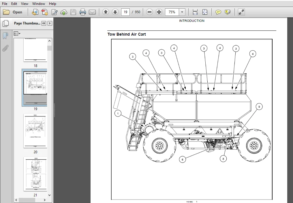
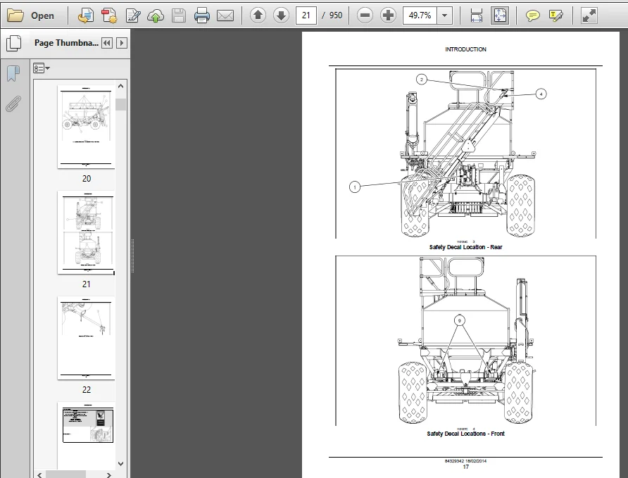
INTRODUCTION
Front axle system 25
[25400] Non-powered front axle 251
Rear axle system 27
[27550] Non-powered rear axle 271
Hydraulic systems 35
[35000] Hydraulic systems351
[35204] Remote control valves 352
[35300] Reservoir, cooler, and filters 353
[35744] Seeding hydraulic circuit354
[35748] Metering system hydraulic circuit355
[35912] Hydraulic seeding fan system 356
Wheels 44
[44511] Front wheels441
[44520] Rear wheels 442
Electrical systems 55
[55000] Electrical system 551
[55100] Harnesses and connectors552
[55301] Alternator553
[55404] External lighting554
[55516] Seeding control system 555
[55517] Cab seeding controls556
[55545] Auger 557
[55640] Electronic modules558
[55954] Split meter control system 559
[55DTC] FAULT CODES5510
84329342 18/02/2014
Metering system 61
[61800] Split meter control system 611
[61904] Product metering 612
Seeding 77
[77100] Product handling and delivery drive system 771
[77101] Seeding fan system 772
[77904] Air distribution system 773
INDEX DETAILS:
Case IH Tractor Precision Air 3580 Air Cart – Complete Service Manual_84329342
Air distribution system – Air flow 3
Air distribution system – Flow test Open Hose Method (*)19
Air distribution system – Flow test Velocity Chart Method (*) 21
Air distribution system – Pneumatic schema 7
Air distribution system – Troubleshooting (*)29
Damper – Flow setting (*) 28
Manifold – Configure 5
Manifold – Exploded view Manifold Lift Cylinder 14
Outlet valve – Pneumatic schema 11
Outlet valve – Pneumatic schema Three tank air carts only 13
Primary air package – Exploded view (*)18
Primary air package – Static description (*)16
PLEASE NOTE:
- This is the same manual used by the DEALERSHIPS to SERVICE your vehicle.
- The manual can be all yours – Once payment is complete, you will be taken to the download page from where you can download the manual. All in 2-5 minutes time!!
- Need any other service / repair / parts manual, please feel free to contact us at heydownloadss @gmail.com . We may surprise you with a nice offer