Case M13K Truck Articulated Forklift Technical Manual – PDF DOWNLOAD
Original price was: $89.95.$28.95Current price is: $28.95.
Case M13K Truck Articulated Forklift Technical Manual – PDF DOWNLOAD
Description
Case M13K Truck Articulated Forklift Technical Manual – PDF DOWNLOAD
DESCRIPTION:
Case M13K Truck Articulated Forklift Technical Manual – PDF DOWNLOAD
GENERAL :
- Do not operate unless the needle on the air pressure gauge is in the green zone. If the needle
cannot be kept in the green zone, use a safe method to move the truck to the repair area.
Do not change the FOPS in any way. - Changes made to the FOPS which are not authorized, such
as welding, drilling or cutting will make the FOPS weaker and decrease your protection.
Replace the FOPS if it becomes damaged in any way. DO NOT TRY TO MAKE REP AIRS TO
THE FOPS. - The injector tip and valve is a matched assembly. The two parts are made smooth to fit together
with accuracy. The injector tip or valve can not be replaced separately for service. If it is
necessary to replace either the valve or tip, replace the complete tip assembly. - Do not mix the
tip assemblies and bodies while the injectors are being disassembled.
Keep dear of this area when engine is running. Machine could pivot unless the pivot safety
lock is in its lock position. Stand to the side of the lock ring when airing tires.
TABLE OF CONTENTS:
Case M13K Truck Articulated Forklift Technical Manual – PDF DOWNLOAD
INTRODUCTION . . . . . . . . . . . . . . . . . . ix
1. Purpose ……………….. ix
2. Scope . . . . . . . . . . . . . . . . . . . . . . ix
3. Terms ………………… ix
I DESCRIPTION ………………. 1-1
1-1. Purpose of Equipment ……. 1-1
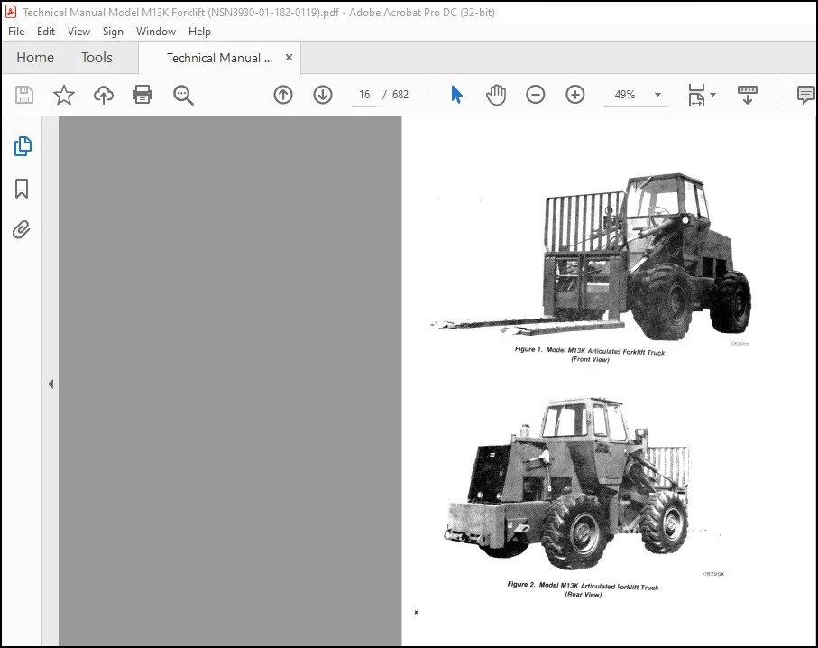
1-2. General Description ……… 1-1
1-3. Component and Systems
Description . . . . . . . . . . . . . . 1-11
1-4. Personnel Cab Assembly ….. 1-11
1-5. Fork/Conveyor …………. 1-11
1-6. Fork Actuator Linkage …… 1-11
1-7. Chassis ………………. 1-11
1-8. Power Train …………… 1-11
1-9. Axle Assemblies ………… 1-12
1-10. Electrical System ……….. 1-15
1-11. Hydraulic System ……….. 1-15
1-12. Pneumatic System ………. 1-22
1-13. Fuel System …………… 1-23
1-14. Cold Start System ………. 1-26
1-15. Cooling System. . . . . . . . . . . . . 1-27
1-16. Hand Operated Winch ……. 1-28
II SPECIAL TOOLS AND TEST
EQUIPMENT . . . . . . . . . . . . . . . . . . . . 2-1
2-1. General . . . . . . . . . . . . . . . . . . . 2-1
III PREPARATION FOR USE ……… 3-1
3-1. Introduction …………… 3-1
3-2. Lubrication ……………. 3-1
3-3. Visual Inspection ……….. 3-1
3-4. Miscellaneous Equipment …. 3-1
3-5. Preparation for Air
Transport. . . . . . . . . . . . . . . . 3-1
3-6. Preparation for Use After
Air Transport . . . . . . . . . . . . 3-4
3-7. Preparation for Rail
Transport. …………… 3-6
3-8. Preparation for Use After
RaH Transport . . . . . . . . . . . 3-6
IV IN USE INSPECTION, MAINTENANCE
AND LUBRICATION ………….. 4-1
4-1. Introduction …………… 4-1
4-2. Troubleshooting . . . . . . . . . . . . 4-1
4-3. Scheduled Inspections ……. 4-1
4-4. Maintenance Safety ……… 4-28
Lubrication . . . . . . . . . . . . . . . . 4-28
General Maintenance . . . . . . . 4-38
Engine Air Cleaning
System. . . . . . . . . . . . . . . . . . 4-38
Spark Arresting Muffler . . . . . 4-41
Drive Belts . . . . . . . . . . . . . . . . 4-41
Engine Cooling System –
General . . . . . . . . . . . . . . . . . 442
Cooling System
Maintenance . . . . . . . . . . . . . 4-43
Fuel System – General . . . . . 4-45
Fuel System
Maintenance . . . . . . . . . . . . . 4-45
Cold Start System ………. 4-47
Braking System . . . . . . . . . . . . 4-48
Electrical System . . . . . . . . . . . 4-49
Cab Components ……….. 4-51
Hydraulic System –
General . . . . . . . . . . . . . . . . . 4-53
Hydraulic System
Maintenance . . . . . . . . . . . . . 4-55
Engine Tuneup Procedure …. 4-57
Engine Speed
Adjustments . . . . . . . . . . . . . 4-73
V OVERHAUL PROCEDURES ……. 5-1
5-1. Introduction …………… 5-1
5-2. General Removal
Instructions . . . . . . . . . . . . . . 5-1
5-3. General Disassembly
Instructions . . . . . . . . . . . . . . 5-1
5-4. General Cleaning
Instructions . . . . . . . . . . . . . . 5-4
5-5. General Inspection
Instructions. . . . . . . . . . . . . . 5-5
5-6. Fluorescent Penetrant
Inspection . . . . . . . . . . . . . . . 5-7
5-7. General Repair
Instructions . . . . . . . . . . . . . . 5-7
5-8. General Assembly and
Installation Instructions . . . 5-8
5-9. Storage ………………. 5-9
5-10. Specific Overhaul
Procedures …………… 5-9
5-11. Forklift Truck Assembly . . . . . 5-9
5-12. Carriage and Fork
Mounting Group . . . . . . . . . . 5-9
5-13. Conveyor Assembly ……… 5-9
5-14. Carriage and Fork
Mounting ……………. 5-12
TABLE OF CONTENTS (Continued)
Section/Para Page Section/Para Page
V 5-15. Forklift Frame and Related V 5-50. Water Pump Group . . . . . . . . 5-136
Parts . . . . . . . . . . . . . . . . . . 5-15 5-51. Water Manifold and
5-16. Lift and Tilt Cylinders ….. 5-15 Thermostat Group ……. 5-144
5-17. Frame Group . . . . . . . . . . . . . 5-21 5-52. Engine Manifold Group. . . . . 5-14 7
5-18. Front Frame Group . . . . . . . . 5-21 5-53. Timing Gear Cover Group … 5-148
5-19. Grille and Hood Group . . . . . 5-23 5-54. Cylinder Head and Cover
5-20. Rear Frame and Trunnion Group ……………… 5-150
Group ……………… 5-23 5-55. Valve Mechanism Group …. 5-165
5-21. Cab Mounting and 5-56. Oil Pan and Oil Pump
Components Group. . . . . . . 5-29 Group. . . . . . . . . . . . . . . . . . 5-184
5-22. Cab Electrical Systems 5-57. Camshaft Group ……….. 5-191
Group ……………… 5-34 5-58. Cylinder Block, Piston and
5-23. Electrical Components. . . . . . 5-34 Connecting Rod Group. . . . 5-208
5-24. Front and Rear Windshield 5-59. Flywheel Housing Group. . . . 5-224
Wipers . . . . . . . . . . . . . . . . . 5-36 5-60. Crankshaft and Flywheel
5-25. Instrument Panel and Group ……………… 5-224
Tachometer Group . . . . . . . 5-39 5-61. Front Oil Seal
5-26. Front Harness Assembly. . . . 5-42 Replacement ………… 5-226
5-27. Lighting Equipment Group .. 5-42 5-62. Rear Oil Seal
5-28. Cab Heater and Defroster Replacement ………… 5-228
System. . . . . . . . . . . . . . . . . 5-42 5-63. Replacement of Main
5-29. Rear Harness Assembly . . . . 5-46 Bearings (without removini
5-30. Battery, Starter and Battery crankshaft) . . . . . . . . . . . . . 5-233
Cables Group . . . . . . . . . . . 5-46 5-64. Crankshaft and Main
5-31. Starter Assembly . . . . . . . . . . 5-46 Bearings . . . . . . . . . . . . . . . 5-238
5-32. Brushholder/End Cap . . . . . . 5-62 5-65. Flywheel . . . . . . . . . . . . . . . . . 5-252
5-33. End Cap . . . . . . . . . . . . . . . . . 5-63 5-66. Oil Filter and Cooler . . . . . . . 5-253
5-34. Field Frame . . . . . . . . . . . . . . 5-64 5-67. Cylinder Block Group . . . . . . 5-255
5-35. Shift Lever Housing …….. 5-68 5-68. Engine Gasket Kits . . . . . . . . 5-255
5-36. Starter Drive Housing …… 5-73 5-69. Transmission and
5-37. Engine Mount Group ……. 5-75 Mounting Parts ………. 5-258
5-38. Alternator and Mounting 5-70. Transmission Assembly. . . . . 5-258
Parts Group …………. 5-79 5-71. Transmission Disassembly . . 5-267
5-39. Radiator, Fan, and Drive 5-72. Removal of Exterior
Belt Group. . . . . . . . . . . . . . 5-94 Components. . . . . . . . . . . . . 5-267
5-40. Air Compressor to 5-73. Removal of Input
Reservoir Group . . . . . . . . . 5-96 Components …………. 5-268
5-41. Air Dryer 5-74. Front Cover, Input Shaft
Assembly ……………… 5-96 and Torque Converter
5-42. Air Compressor Assembly. . . 5-99 Group ……………… 5-269
5-43. Compressor Cylinder Block 5-75. Converter/Transmission
and Crankcase ………. 5-104 Housings and Gears …… 5-269
5-44. Air Compressor Governor … 5-112 5-76. Removal of Converter
5-45. Fuel Injection System Components and Housing . 5-272
Group ……………… 5-116 5-77. Turbine Driven Gears,
5-46. Fuel Injection Nozzle ……. 5-118 Freewheel Unit and Front
5-47. Fuel Injection Pump ……. 5-126 Cover ……………… 5-273
5-48. Fuel Filter System ……… 5-134 5-78. Removal of Turbine
5-49. Fuel Injection Pump and Gearing and Oil Suction
Drive ……………… 5-136 Tube ………………. 5-275
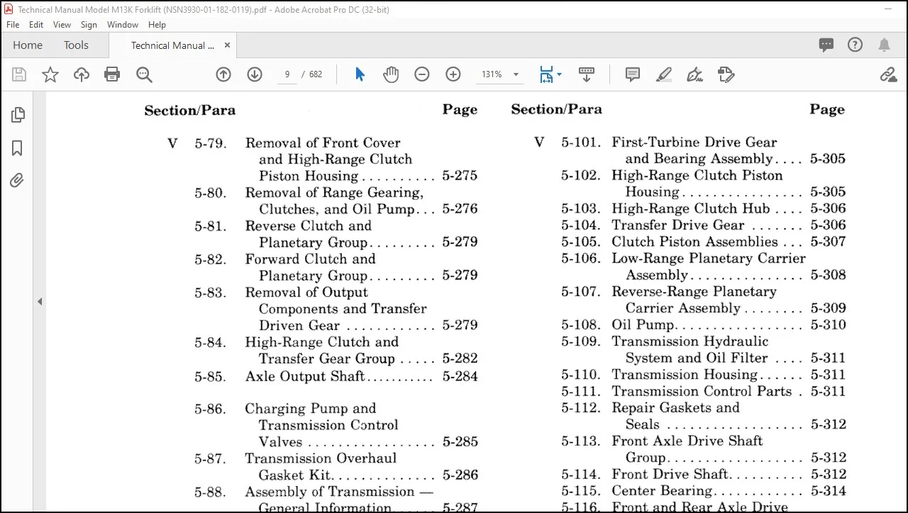
V 5-79. Removal of Front Cover V 5-101. First-Turbine Drive Gear
and High-Range Clutch and Bearing Assembly. . . . 5-305
Piston Housing ………. 5-275 5-102. High-Range Clutch Piston
5-80. Removal of Range Gearing, Housing . . . . . . . . . . . . . . . . 5-305
Clutches, and Oil Pump … 5-276 5-103. High-Range Clutch Hub . . . . 5-306
5-81. Reverse Clutch and 5-104. Transfer Drive Gear ……. 5-306
Planetary Group. . . . . . . . . 5-279 5-105. Clutch Piston Assemblies . . . 5-307
5-82. Forward Clutch and 5-106. Low-Range Planetary Carrier
Planetary Group. . . . . . . . . 5-279 Assembly. . . . . . . . . . . . . . . 5-308
5-83. Removal of Output 5-107. Reverse-Range Planetary
Components and Transfer Carrier Assembly …….. 5-309
Driven Gear ………… 5-279 5-108. Oil Pump …………….. 5-310
5-84. High-Range Clutch and 5-109. Transmission Hydraulic
Transfer Gear Group . . . . . 5-282 System and Oil Filter …. 5-311
5-85. Axle Output Shaft ……….. 5-284 5-110. Transmission Housing …… 5-311
5-111. Transmission Control Parts . 5-311
5-86. Charging Pump and 5-112. Repair Gaskets and
Transmission Control Seals ……………… 5-312
Valves …………….. 5-285 5-113. Front Axle Drive Shaft
5-87. Transmission Overhaul Group ……………… 5-312
Gasket Kit. . . . . . . . . . . . . . 5-286 5-114. Front Drive Shaft ………. 5-312
5-88. Assembly of Transmission – 5-115. Center Bearing ………… 5-314
General Information. . . . . . 5-287 5-116. Front and Rear Axle Drive
5-89. Installation of Output Shaft Group. . . . . . . . . . . . . 5-316
Components, Transfer Driven 5-117. Center Drive Shaft. . . . . . . . . 5-316
Gear ………………. 5-288 5-118. Rear Drive Shaft ………. 5-318
5-90. Installation of Range 5-119. Slip Yoke ……………. 5-318
Clutches and Gearing …. 5-289 5-120. Universal Joint . . . . . . . . . . . 5-318
5-91. Installation of High-Range 5-121. Axle and Mounting …….. 5-319
Clutch Piston Housing and 5-122. Wheels and Tires . . . . . . . . . . 5-320
Front Cover. . . . . . . . . . . . . 5-292 5-123. Axle Housing and
5-92. Installation of Turbine Planetary Group. . . . . . . . . 5-322
Gearing and Oil Suction 5-124. Planetary . . . . . . . . . . . . . . . . 5-322
Tube ………………. 5-293 5-125. Ring Gear and Wheel Hub . . 5-326
5-93. Installation of Converter 5-126. Axle Spindle . . . . . . . . . . . . . . 5-329
Housing and Converter 5-127. Axle Breather. . . . . . . . . . . . . 5-331
Components. . . . . . . . . . . . . 5-294 5-128. Differential and Carrier
5-94. Installation of Input Assembly . . . . . . . . . . . . . . . 5-331
Components …………. 5-295 5-129. Reservoir to Treadles, Brake
5-95. Installation of Exterior Actuator and Clutch Cutout
Components …………. 5-296 Group. . . . . . . . . . . . . . . . . . 5-34 7
5-96. Control Valve Body …….. 5-297 5-130. Air Reservoir . . . . . . . . . . . . . 5-34 7
5-97. First and Second Turbine 5-131. Double Check Valve Assembly
Assembly …………… 5-298 and Stoplamp Switch . . . . . 5-349
5-98. Torque Converter Pump . . . . 5-299 5-132. Brake Treadle and Valve
5-99. Torque Converter Housing . . 5-300 Assembly. . . . . . . . . . . . . . . 5-355
5-100. Turbine-Driven Gears and 5-133. Brake Actuator. . . . . . . . . . . . 5-366
Freewheel Clutch …….. 5-303 5-134. Hydraulic Brake Cylinder … 5-368
Section/Para Page Section/Para Page
V 5-135. Air Chamber. . . . . . . . . . . . . . 5-369 V 5-165. Fork Tilt Hydraulic Circuit . 5-468
5-136. Brake Actuator to Wheel 5-166. Forklift Control Valve
Cylinder Group. . . . . . . . . . 5-370 and Levers. . . . . . . . . . . . . . 5-468
5-137. Disc Brake Master Cylinder 5-167. Fuel Tank and Related
System. . . . . . . . . . . . . . . . . 5-372 Parts ……………… 5471
5-138. Brake Fluid Reservoir . . . . . . 5-372 5-168. Accelerator and Linkage
5-139. Brake Calipers ………… 5-373 Group …………………. 5-471
5-140. Treadle to Hydraulic Tank 5-169. Winch and Mounting Parts .. 5-474
and Hom Group . . . . . . . . . 5-378 5-170. Cold Start System ……….. 5-474
5-141. Horn Valve Assembly . . . . . . 5-380 5-171. Decals and Plates Group …. 5-477
5-142. Pressure Protection Valve
Assembly …………… 5-381 VI CLEANING ………………… 6-1
5-143. Pressure Regulator Valve 6-1. Introduction . . . . . . . . . . . . . . 6-1
Assembly. . . . . . . . . . . . . . . 5-388
5-144. Horn Assembly. . . . . . . . . . . . 5-389 VII INSPECTION, REPAIR AND
5-145. Parking Brake REPLACEMENT ……………. 7-1
Linkage ………………. 5-391 7-1. Introduction . . . . . . . . . . . . . . 7-1
5-146. Parking Brake Caliper …… 5-393
5-147. Deleted VIII TESTING ………………….. 8-1
5-148. Steering Control Valve and 8-1. General ……………… 8-1
Related Parts . . . . . . . . . . . 5-395 8-2. Battery Tests . . . . . . . . . . . . . 8-1
5-149. Steering Control Valve and 8-3. Battery Charging. . . . . . . . . . 8-6
Column Assembly …….. 5-395 8-4. Starting Circuit Tests . . . . . . 8-7
5-150. Steering Control Valve to 8-5. Starter No-Load Test ……. 8-13
Cylinders Group . . . . . . . . . 5410 8-6. Starter Solenoid Tests . . . . . . 8-15
5-151. Steering Cylinders ……… 5-413 8-7. Alternator Tests. . . . . . . . . . . 8-17
5-152. Steering Hydraulic Circuit .. 5-415 8-8. Fuel Injector Tests ……… 8-20
5-153. Flow Control Valve …….. 5-417 8-9. Transmission Tests . . . . . . . . 8-22
5-154. Hydraulic and Steering Pump 8-10. Stall Tests ……………. 8-25
Assembly …………… 5-418 8-11. Air System Tests ………. 8-28
5-154A.Auxiliary Steering Group … 5-431 8-12. Steering Relief Valve
5-154B.Auxiliary Steering Pump and Pressure Check. . . . . . . . . . 8-30
Motor and Related Parts .. 5-431 8-13. Hydraulic Cylinder Tests . . . 8-31
5-154C.Auxiliary Steering Pump …. 5-436 8-14. Flowmeter Test Number
5-154D.Auxiliary Steering Motor …. 5-438 One ………………. 8-33
5-155. Hydraulic Tank and 8-15. Flowmeter Test Number
Related Parts . . . . . . . . . . . 5-445 Two ………………. 8-37
5-156. Pump to Reservoir Hydraulic 8-16. Flowmeter Test Number
Circuit . . . . . . . . . . . . . . . . . 5-446 Three ……………… 8-39
5-157. Pump to Control Valve 8-17. Flowmeter Test Number
Hydraulic Circuit …….. 5-446 Four ………………. 841
5-158. Hydraulic Control Valve …. 5-446 8-18. Fail Safe Valve Test. . . . . . . . 842
5-159. Main Relief Valve ……… 5-451 8-19. Auxiliary Steering Motor
5-160. Control Valve Spool and Pump Tests ……….. 8-42
Assembly. . . . . . . . . . . . . . . 5456 5-161. Load Check Valve . . . . . . . . . 5-462 IX TABLE OF LIMITS ………….. 9-1
5-162. Lift Arms Hydraulic 9-1. Introduction ………….. 9-1
Circuit Group . . . . . . . . . . . 5-463 9-2. Specific Torque
5-163. Fork Spacing Hydraulic Specifications . . . . . . . . . . . 9-1
Circuit Group ……….. 5-465 9-3. General Torque Values ….. 9-1
5-164. Fork Spacing Cylinder 9-4. Table of Limits. . . . . . . . . . . . 9-1
Assembly …………… 5-465 9-5. Table of Miscellaneous
Limits …………….. 9-1
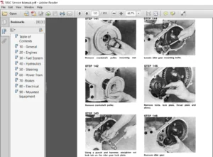
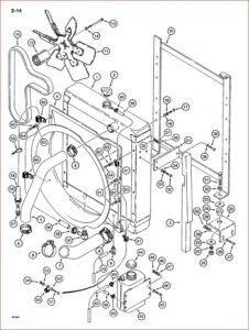
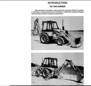
IMAGES PREVIEW OF THE MANUAL:
Contact us: [email protected]
PLEASE NOTE:
- This is not a physical manual but a digital manual – meaning no physical copy will be couriered to you. The manual can be yours in the next 2 mins as once you make the payment, you will be directed to the download page IMMEDIATELY.
- This is the same manual used by the dealers inorder to diagnose your vehicle of its faults.
- Require some other service manual or have any queries: please WRITE to us at [email protected]
S.V