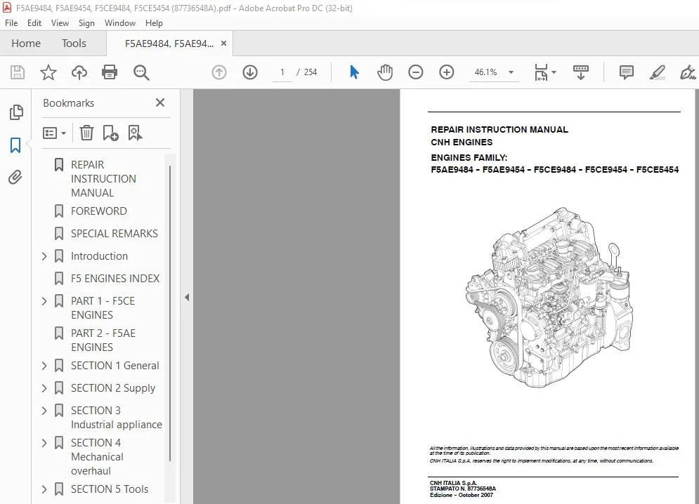
Case New Holland F5AE9484 F5AE9454 F5CE9484 F5CE9454 F5CE5454 Repair Instruction Manual
Original price was: $89.95.$28.95Current price is: $28.95.
Case New Holland F5AE9484 F5AE9454 F5CE9484 F5CE9454 F5CE5454 Repair Instruction Manual – PDF DOWNLOAD
Description
Case New Holland F5AE9484 F5AE9454 F5CE9484 F5CE9454 F5CE5454 Repair Instruction Manual – PDF DOWNLOAD
DESCRIPTION:
Case New Holland F5AE9484 F5AE9454 F5CE9484 F5CE9454 F5CE5454 Repair Instruction Manual – PDF DOWNLOAD
PREFACETOUSER’SGUIDELINE MANUAL :
Manuals for repairs are split into Parts and Sections, each one of which is marked by a numeral; the contents of these sections are
indicated in the general table of contents.
The sections dealing with things mechanic introduce the specifications, tightening torque values, tool lists, assembly
detaching/reattaching operations, bench overhauling operations, diagnosis procedures and maintenance schedules.
The sections (or parts) of the electric/electronic system include the descriptions of the electric network and the assembly’s
electronic systems, wiring diagrams, electric features of components, component coding and the diagnosis procedures for the
control units peculiar to the electric system.
Section 1 describes the engines illustrating its features and working in general.
Section 2 describes the type of fuel feed.
Section 3 relates to the specific duty and is divided in four separate parts:
1. Mechanical part, related to the engine overhaul, limited to those components with different characteristics based on the relating
specific duty.
2. Electrical part, concerning wiring harness, electrical and electronic equipment with different characteristics based on the relating
specific duty.
3. Maintenance planning and specific overhaul.
4. Troubleshooting part dedicated to the operators who, being entitled to provide technical assistance, shall have simple and direct
instructions to identify the cause of the major inconveniences.
Sections 4 and 5 illustrate the overhaul operations of the engine overhaul on stand and the necessary equipment to execute such
operations.
The appendix contains a list of the general safety regulations to be respected by all installation and maintenance engineers in order
to prevent serious accidents taking place.
The manual uses proper symbols in its descriptions; the purpose of these symbols is to classify contained information. In particular,
there have been defined a set of symbols to classify warnings and a set for assistance operations.
TABLE OF CONTENTS:
Case New Holland F5AE9484 F5AE9454 F5CE9484 F5CE9454 F5CE5454 Repair Instruction Manual – PDF DOWNLOAD
REPAIR INSTRUCTION MANUAL…………………………… 1
FOREWORD………………………………………….. 3
SPECIAL REMARKS……………………………………. 5
Introduction………………………………………. 7
PREFACETOUSER’SGUIDELINEMANUAL…………………… 9
GENERAL WARNINGS……………………………….. 11
GENERAL WARNINGSON THE ELECTRICSYSTEM…………….. 13
Bonding and screening…………………………… 14
OPTIONAL ELECTRICAL…………………………….. 15
F5 ENGINES INDEX…………………………………… 17
PART 1 – F5CE ENGINES………………………………. 19
SECTION 1 General specifications…………………. 21
TECHNICAL CODING……………………………. 23
ENGINE VIEWS……………………………….. 24
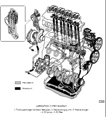
LUBRICATION SYSTEM………………………….. 27
Oil pump…………………………………… 28
Engine oil filter…………………………… 29
ENGINE OIL VAPOUR RECIRCULATION………………. 30
ENGINE COOLING SYSTEM……………………….. 31
WATER PUMP…………………………………. 32
HEAT EXCHANGER……………………………… 33
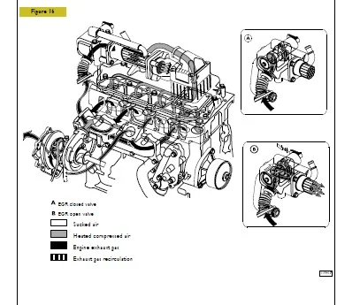
EGR EXHAUST GAS RECIRCULATION………………… 34
EXTERNAL E.G.R. (F5CE5454 ENGINES)……………. 35
BOOSTING…………………………………… 36
SECTION 2 Supply……………………………….. 37
SUPPLY…………………………………….. 39
PIPE LAYOUT………………………………… 40
SUPPLY PUMP………………………………… 42
WORKING SYSTEM DESCRIPTION…………………… 43
L.D.A. Load Delivery Adjustment device………… 45
PRIMING PUMP……………………………….. 46
FUEL FILTER………………………………… 47
SECTION 3 Industrial application…………………. 49
MAIN SPECIFICATIONS…………………………. 51
PART ONE – MECHANICAL COMPONENTS……………… 53
ENGINE DISASSEMBLY ON BENCH………………. 55
BOSCH VE4/12F Pump………………………. 57
Timing gear case………………………… 60
Timing…………………………………. 64
Check sand inspections…………………… 70
PART TWO – ELECTRICAL EQUIPMENT………………. 71
CABLE FOR ENGINE SWITH EXTERNAL EGR SYSTEM…. 73
EGR E.C.U. ELECTRICAL LAYOUT……………… 74
EGR E.C.U………………………………. 75
Pin out EGR E.C.U……………………….. 76
ELECTRIC CABLE TO CONNECT KSB WITH CERA……. 77
Oil pressure switch……………………… 79
Cooling liquid temperature sensor for KSB….. 80
Air pressure temperature sensor…………… 81
Engine drive shaft sensor………………… 82
EGR Solenoid valve………………………. 83
Starter………………………………… 84
PART THREE – TROUBLESHOOTING…………………. 85
DIAGNOSIS BY FAILURE…………………….. 87
PART FOUR – MAINTENANCE PLANNING……………… 93
SCHEDULED MAINTENANCE……………………. 95
SECTION 4 Mechanical overhaul……………………. 97
GENERAL SPECIFICATIONS………………………. 99
ENGINE OVERHAUL……………………………..106
REPAIRS CYLINDER UNIT………………………..107
TIMING SYSTEM……………………………….109
ENGINE DRIVE SHAFT…………………………..112
CYLINDER HEAD……………………………….122
VALVES……………………………………..123
VALVE GUIDE…………………………………124
VALVES PRINGS……………………………….125
CYLINDER HEAD ASSEMBLY……………………….125
TORQUE SETTING………………………………127
SECTION 5 Tools…………………………………131
TOOLS………………………………………133
Appendix……………………………………….137
SAFETY PRESCRIPTIONS…………………………….139
PART 2 – F5AE ENGINES……………………………….141
SECTION 1 General ………………………………….143
TECHNICAL CODING………………………………..145
ENGINE VIEWS……………………………………146
LUBRICATION…………………………………….149
Oil pump……………………………………….150
Engine oil filter……………………………….152
ENGINE OIL VAPOUR RECIRCULATION…………………..153
COOLINGSYSTEM…………………………………..154
WATER PUMP……………………………………..155
HEAT EXCHANGER………………………………….156
TURBOCHARGING…………………………………..157
EGR EXHAUST GAS RECIRCULATION…………………….158
SECTION 2 Supply……………………………………159
SUPPLY…………………………………………161
PIPE LAYOUT…………………………………….162
SUPPLY PUMP…………………………………….164
WORKING SYSTEM DESCRIPTION……………………….165
L.D.A. Load Delivery Adjustment device…………….167
PRIMING PUMP……………………………………168
FUEL FILTER…………………………………….169
SECTION 3 Industrial appliance……………………….171
MAIN SPECIFICATIONS……………………………..173
PART ONE -MECHANICAL COMPONENTS………………….175
ENGINE DISASSEMBLY ON BENCH…………………..177
BOSCH VE4/12F Pump…………………………..178
Timing gear case…………………………….181
Timing……………………………………..185
Check sand inspections……………………….191
PART TWO – ELECTRICAL EQUIPMENT…………………..193
ELECTRIC CABLE TO CONNECT KSB WITH CERA………..195
Oil pressure switch………………………….197
Cooling liquid temperature sensor for KSB………198
Engine pulse transmitter……………………..199
PART THREE – DIAGNOSIS…………………………..201
DIAGNOSIS BY FAILURE…………………………203
PART FOUR SCHEDULED MAINTENANCE…………………..209
SCHEDULED MAINTENANCE………………………..211
SECTION 4 Mechanical overhaul………………………..213
GENERAL SPECIFICATIONS…………………………..215
ENGINE OVERHAUL…………………………………222
REPAIRS CYLINDER UNIT……………………………223
TIMING SYSTEM…………………………………..225
ENGINE DRIVE SHAFT………………………………228
VALVES…………………………………………238
VALVEGUIDE……………………………………..239
VALVESPRINGS……………………………………240
TORQUE SETTING………………………………….241
SECTION 5 Tools…………………………………….245
TOOLS………………………………………….247
SAFETY PRESCRIPTIONS………………………………..253
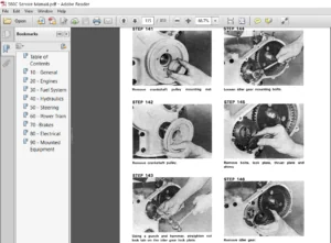
IMAGES PREVIEW OF THE MANUAL:
CASE NEW HOLLAND F5AE9484 F5AE9454 F5CE9484 F5CE9454 F5CE5454 REPAIR INSTRUCTION MANUAL:
PLEASE NOTE:
- This is the SAME exact manual used by your dealers to fix your vehicle.
- The same can be yours in the next 2-3 mins as you will be directed to the download page immediately after paying for the manual.
- Any queries / doubts regarding your purchase, please feel free to contact [email protected]
S.V