Case Poclain 75C-90C Service Manual 01-0018E – PDF DOWNLOAD
Original price was: $89.95.$19.95Current price is: $19.95.
Case Poclain 75C-90C Service Manual 01-0018E – PDF DOWNLOAD
Description
Case Poclain 75C-90C Service Manual 01-0018E – PDF DOWNLOAD
DESCRIPTION:
Case Poclain 75C-90C Service Manual 01-0018E – PDF DOWNLOAD
- The 75C and 90C are track-mounted hydraulic excavators.
- They are designed for earthmoving operation on all kinds of terrain.
- These machines benefit from the experience acquired from other models in the Podain range, and incorporate
the latest advances as regards both technique and comfort
Thanks to Podain’s Variodyn hydraulic circuit, optimum use is made of the power available, and as a result a
high output can be obtained from these machines. - Owing to the wide range of attachments which can be mounted, the 75C and 90C are versatile machines, we!!
suited for earthmoving, rehandling, winning, boring, ditch•cleaning, etc”…
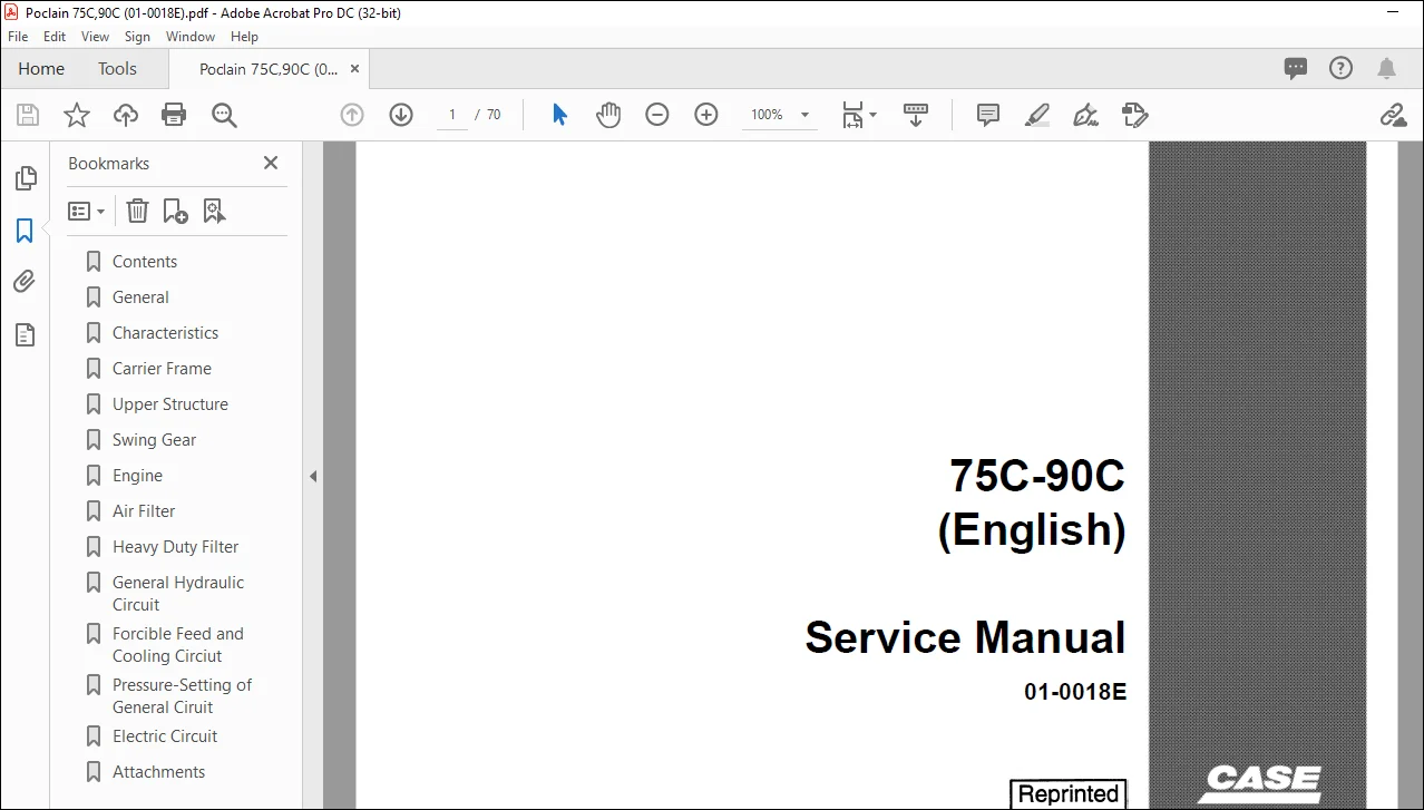
TABLE OF CONTENTS:
Case Poclain 75C-90C Service Manual 01-0018E – PDF DOWNLOAD
GENERAL DESCRIPTION ………………………………………………… .
CHARACTERISTICS ……………………………………………………. .
CARRIER FRAME ………………………..
– Track group …………………………………………………………. .
– Pinion-type reduction gear ………………………………………………. .
– Tensioner and shock-absorber …………………………………………….. .
– Rollers. . . . . . . . . . . . . . . . . . . . . . . . . . . . . . . . . . . . . . . . . . . . . . . . . . . . . . . . …………… .
– Tracks• Pads ………………………………………………………… .
UPPERSTRUCTURE ……………………………………………………. .
SWING GEAR …………………………………………….
ENGINE ……………………………………………………………
DRY-TYPE AIR FILTER ………………………………………………… .
HEAVY DUTY FILTER ………………………………………………….. .
GENERAL HYDRAULIC CIRCUIT
— General layout. . . . . . . . . . . . . . . . . . . . . . . . . . . . . . . . . . . . . . . . . . . . . . . . . . . . . . . . . . . . . . . . . . 18
– Operation …………………………………………………………… 20 to 25
– Description ………………………………………………………….. 26 to 29
– Components :
Hydraulic oil tank . . . . . . . . . . . . . . . . . . . . . . . . . . . . . . . . . . . . . . . . . . . . . . . . . . . . . . . . . . . . . 30
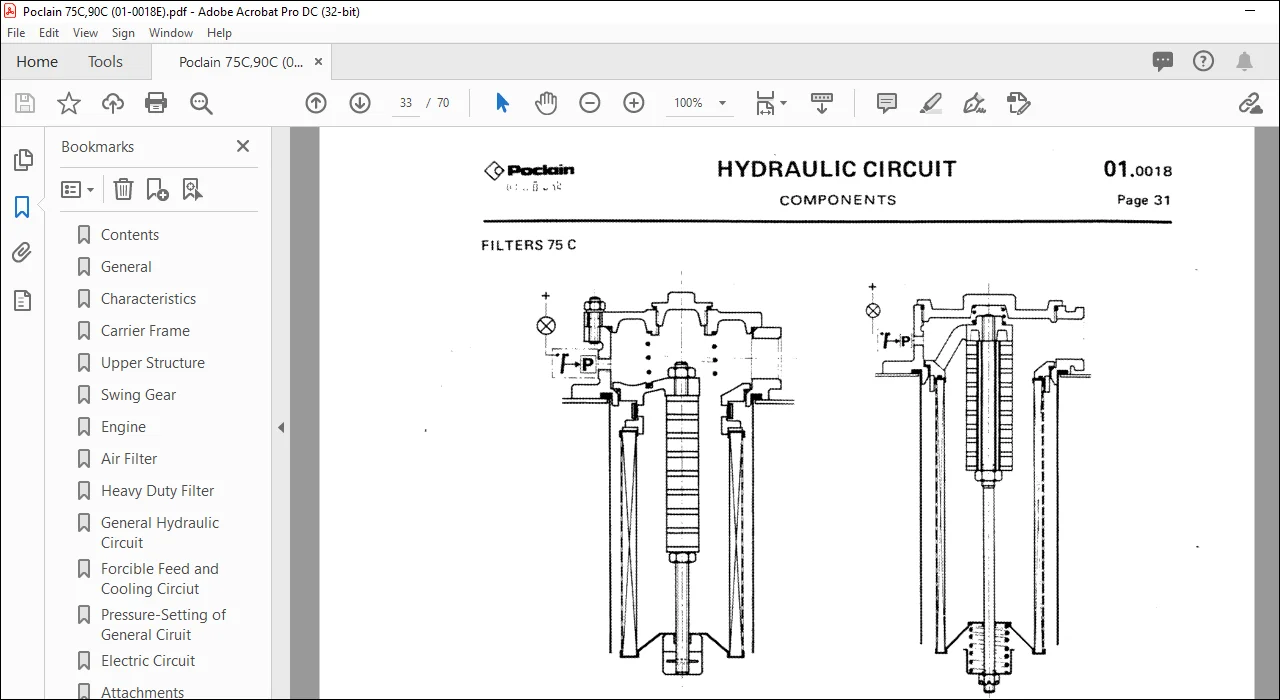
Hydraulic filters . . . . . . . . . . . . . . . . . . . . . . . . . . . . . . . . . . . . . . . . . . . . . . . . . . . . . . . . . . . . . . 31
Hydraulic pump …………………………………………………….. 32 to 33
Make and break assembly ………………………………………………. 34 to 35
Valve bank control . . . . . . . . . . . . . . . . . . . . . . . . . . . . . . . . . . . . . . . . . . . . . . . . . . . . . . . . . . . . 36
3 S19 valve banks . . . . . . . . . . . . . . . . . . . . . . . . . . . . . . . . . . . . . . . . . . . . . . . . . . . . . . . . . . . . . 37
S19 inlet block ……………………………………………………… 38 to 39
Discharge valve . . . . . . . . . . . . . . . . . . . . . . . . . . . . . . . . . . . . . . . . . . . . . . . . . . . . . . . . . . . . . . 40
S19 control valves. . . . . . . . . . . . . . . . . . . . . . . . . . . . . . . . . . . . . . . . . . . . . . . . . . . . . . . . . . . . . 41
S19 safety valve.. . . . . . . . . . . . . . . . . . . . . . . . . . . . . . . . . . . . . . . . . . . . . . . . . . . . . . . . . . . . . . 42
3 P22 valve banks . . . . . . . . . . . . . . . . . . . . . . . . . . . . . . . . . . . . . . . . . . . . . . . . . . . . . . . . . . . . . 43
P22 control valves. . . . . . . . . . . . . . . . . . . . . . . . . . . . . . . . . . . . . . . . . . . . . . . . . . . . . . . . . . . . . 44
P22 forcible feed/safety block . . . . . . . . . . . . . . . . . . . . . . . .. . . . . . . . . . . . . . . . . . . . . . . . . . . 45
• Flow regulator valve . . . . . . . . . . . . . . . . . . . . . . . . . . . . . . . . . . . . . . . . . . . . . . . . . . . . . . . . . . . 46
Hydraul’ic motors ……………………………………………………. 4 7 to 48
Swing joint…………. . . . . . . . . . . . . . . . . . . . . . . . . . . . . . . . . . . . . . . . . . . . . . . . . . . . . . 49
Double-acting hydraulic cylinders. . . . . . . . . . . . . . . . . . . . . . . . . . . . . . . . . . . . . . . . . . . . . . . . . 50
FORCIBLE FEED ANO COOLING Cl RCUIT
– Diagrammatic layout……………………………………………….. . . . . . 52
-· Components :
· Cooler……………………………………………………………. 53
Hydraulic accumulator . . . . . . . . . . . . . . . . . . . . . . . . . . . . . . . . . . . . . . . . . . . . . . . . . . . . . . . . . 53
Gear-type pump . . . . . . . . . . . . . . . . . . . . . . . . . . . . . . . . . . . . . . . . . . . . . . . . . . . . . . . . . . . . . 54
Gear-type motor . . . . . . . . . . . . . . . . . . . . . . . . . . . . . . . . . . . . . . . . . . . . . . . . . . . . . . . . . . . . . . 54
• Counter-pressure valve. . . . . . . . . . . . . . . . . . . . . . . . . . . . . . . . . . . . . . . . . . . . . . . . . . . . . . . . . . 55
PRESSURE-SETTING OF GENERAL CIRCUIT …………………………………. 56 to 57
ELECTRIC CIRCUIT
– Diagram. . . . . . . . . . . . . . . . . . . . . . . . . . . . . . . . . . . . . . . . . . . . . . . . . . . . . . . . . . . . . . . . . . . . . . . 58
– Description ………………………………………………………….. 59 to 60
ATTACHMENTS ……………………….•……………………………… 61 to63
IMAGES PREVIEW OF THE MANUAL:
CASE POCLAIN 75C-90C SERVICE MANUAL 01-0018E – PDF DOWNLOAD:
PLEASE NOTE:
- This is the SAME exact manual used by your dealers to fix your vehicle.
- The same can be yours in the next 2-3 mins as you will be directed to the download page immediately after paying for the manual.
- Any queries / doubts regarding your purchase, please feel free to contact [email protected]
S.V