Case Skid Steer Loader Service Manual SR/SV/TR Series – Engine Transmission PDF
Original price was: $95.00.$28.95Current price is: $28.95.
Complete 204-page factory service manual for Case Construction skid steer loaders and compact track loaders covering SR130/SR150/SR175/SR200/SR220/SR250, SV185/SV250/SV300, and TR270/TR320/TV380 models. Comprehensive technical documentation for engine systems, fuel injection, air intake, coolant systems, starting systems, hydrostatic transmission, drive motors, pressure testing, and relief valve procedures with detailed diagrams and step-by-step instructions.
Description
Case Skid Steer Loader Service Manual SR/SV/TR Series – Engine Transmission PDF DOWNLOAD
![]()
![]()
DESCRIPTION
Official Factory Service Manual for Case Skid Steer Loaders & Compact Track Loaders
This authentic Case Construction service manual PDF provides complete factory-authorized technical documentation for servicing, repairing, and maintaining multiple models of skid steer loaders and compact track loaders. Essential for heavy equipment technicians, fleet maintenance departments, construction equipment mechanics, and Case dealerships responsible for these Case skid steer and track loader machines.
FILE DETAILS
- Manual Name: Case Construction Equipment Service Manual – Engine and Transmission Sections
- Manual Number: 84423866 (July 25, 2011)
- Models Covered: 12 models across SR, SV, and TR series
- PDF Quality: Excellent – Factory diagrams and illustrations
- Total Pages: 204 pages
- Language: English
COMPLETE MODEL COVERAGE
Skid Steer Loaders – SR Series:
- SR130 – Compact skid steer loader
- SR150 – Compact skid steer loader
- SR175 – Medium-frame skid steer loader
- SR200 – Medium-frame skid steer loader
- SR220 – Medium-frame skid steer loader
- SR250 – Large-frame skid steer loader
Skid Steer Loaders – SV Series (Vertical Lift):
- SV185 – Medium-frame vertical lift loader
- SV250 – Large-frame vertical lift loader
- SV300 – Large-frame vertical lift loader
Compact Track Loaders – TR/TV Series:
- TR270 – Medium-frame track loader
- TR320 – Large-frame track loader
- TV380 – Large-frame track loader
SECTION B: ENGINE AND PTO IN
B.10.A – ENGINE SYSTEMS
Engine Removal Procedures:
- Small/Medium Frame Models (SR130, SR150, SR175, SV185):
- Complete step-by-step disassembly sequence
- Electrical connector disconnections (starter, alternator)
- Temperature and oil pressure sender wire removal
- Throttle cable disconnection procedures
- Wire harness and clamp removal from flywheel housing
- Fuel supply and return line disconnection
- Remote engine oil filter line disconnection
- Ground cable removal from battery disconnect
- Hydraulic pump mounting bolt removal (12 bolts)
- Engine oil pan drain hose procedures
- Front and rear engine mount removal
- Fixed hood removal (4 mounting bolts)
- Engine lifting and extraction procedures
- Large Frame Models (SR200, SR220, SR250, SV250, SV300, TR270, TR320, TV380):
- Model-specific removal procedures
- Heavier component handling requirements
- Additional mounting point considerations
Engine Installation Procedures:
- Reverse installation sequences for all models
- Torque specifications for all fasteners
- Proper alignment procedures
- Electrical reconnection verification
- Fluid line connection and leak checks
- Final testing and verification
B.20.A – FUEL AND INJECTION SYSTEM
Fuel Tank Service:
- Left-hand side fuel tank bracket removal
- Right-hand side fuel tank bracket removal
- Fuel draining procedures using bottom drain plug
- Complete fuel tank removal and installation
- Fuel supply line connection/disconnection
- Fuel level sender service procedures
Fuel Level Sender (B-001):
- Rear engine hood access procedures
- Air filter housing hardware removal for access
- Connector X-14 disconnection procedures
- Fuel line labeling and disconnection
- Sender retainer hardware removal
- Fuel level sender removal from tank
- Installation procedures with proper sealing
- Electrical connector verification
Fuel Shut-Off Solenoid:
- Spade connector service
- Solenoid testing procedures
- Replacement guidelines
Safety Warnings Included:
- Fire hazard precautions during fuel handling
- No smoking policies
- Engine-off refueling requirements
- Immediate spill cleanup procedures
- Escaping fluid hazards under pressure
- Hydraulic/diesel fuel penetration injury prevention
- Proper leak detection techniques (cardboard/wood, never hands)
- Emergency medical treatment for fluid injection injuries
B.30.A – AIR INTAKE SYSTEM
Air Filter Service:
- Filter housing access procedures
- Filter element removal and replacement
- Pre-cleaner service (if equipped)
- Restriction indicator inspection
- Housing inspection for cracks or damage
- Inlet ducting inspection
- Clamp and seal verification
Turbocharger Systems:
- Intake manifold connections
- Turbocharger inspection access
- Boost pressure verification
- Wastegate operation (if equipped)
B.50.A – ENGINE COOLANT SYSTEM
Cooling System Service:
- Coolant drain procedures
- Radiator service and cleaning
- Coolant hose inspection and replacement
- Thermostat testing and replacement
- Water pump service procedures
- Radiator cap pressure testing
- Coolant recovery system service
- System pressure testing for leaks
- Proper coolant mixture specifications
- Refilling and bleeding procedures
B.80.A – STARTING SYSTEM
Glow Plug System (Cold Start Aid):
- Engine preheating operation overview
- Diesel combustion chamber temperature requirements
- Compression-ignition principles
- Glow plug function in each cylinder
- Cold start temperature compensation
- Piston compression cycle and fuel injection timing
Ignition Switch Testing:
- Complete diagnostic flowchart with 10 test points
- Main power relay control verification
- Wire harness continuity testing between connectors:
- Connector X-9 to X-316 (pin 3 to pin A)
- Connector X-9 to X-C23 (pin 3 to pin 21)
- Connector X-9 to X-C23 (pins 2 to pins 9 and 11)
- Connector X-9 to X-C23 (pin 1 to pin 3)
- Connector X-9 to X-15 (pin 6 to pin 1)
- Connector X-15 to X-C23 (pin 2 to pin 22)
- Ignition Backfeed Diode (V-007) testing
- Accessory Backfeed Diode (V-004) testing
- Instrument cluster pin verification (pins 3, 9, 11, 21, 22)
- Wire color code identification for troubleshooting:
- Wire 132/133 (Orange)
- Wire 132 (Orange) / 131 (White)
- Wire 624/622 (White) and 624/623 (White)
- Wire 140 (Red) / 311 (Yellow)
- Wire 138 (Orange) / 153 (Black)
- Wire 137 (White)
- Cross-reference to electrical schematics (frames 03, 04, 14)
- Component replacement procedures for failed parts
SECTION C: TRANSMISSION, DRIVE AND PTO OUT
C.20.F – HYDROSTATIC TRANSMISSION
TECHNICAL DATA – Pump Specifications:
35cc EH (Electro Hydraulic) Pump:
- Used in small/medium frame models: SR130, SR150, SR175, SV185 (EH controls)
- Manufacturer: Sauer-Danfoss
- Type: Axial piston pump
- Displacement: 35 cm³ (2.1 in³)
- Detailed specifications for electronic control systems
46cc EH Hydrostatic Pump:
- Models: SR220, SR250, SV250, SV300, TR270, TR320, TV380 (EH controls)
- Manufacturer: Sauer-Danfoss
- Combination pump design
- Clockwise rotation
- Nominal displacement: 46 cm³ (2.8 in³)
- Maximum displacement port A: 46 cm³ ± 0.9 cm³
- Maximum displacement port B: 46 cm³ ± 0.9 cm³
- Shaft test speed: 2000 RPM
- Charge pressure: 25 bar (363 psi ± 15 psi)
- Relief valve A: 385 bar (5583 psi ± 145 psi)
- Relief valve B: 385 bar (5582 psi ± 145 psi)
- Differential pressure specifications
- Nominal voltage: 12V
- Complete port identification (A, B, T, X1, X2, R, Ma, Mb, G, G2, S, Mg, Yst)
46cc EHF Hydrostatic Pump (Large Frame):
- Models: SR250, SV300, TV380 (EH controls)
- Advanced features for heavy-duty applications
35cc Mechanical Control Tandem Pump:
- Models: SR130, SR150, SR175, SV185 (mechanical controls)
- Manual swashplate displacement control
- 19.05 mm (0.75 in) square input shaft
- Charge pressure relief: 24-25 bar (348-363 psi) @ 1800 RPM
- System pressure relief: 345 bar (5003 psi) +5/0%
46cc Mechanical Tandem Pump:
- Models: SV185, SR200, SR220, SR250, SV250, SV300, TR270, TR320, TV380
- Clockwise rotation
- Front and rear displacements: 46 cm³ (2.8 in³)
- Bushed block rotating speed: up to 3600 RPM
- Manual displacement control
53cc Hydrostatic Pump (Large Frame):
- Models: SR250, SV300, TV380 (EH controls)
- Manufacturer: Rexroth
- Piston pump design
- Nominal displacement: 63 cm³ (3.8 in³)
- Test speed: 2800 RPM
- Charge pressure: 25 bar (363 psi)
- Relief valve A: 276 bar (4002 psi)
- Relief valve B: 207 bar (3002 psi)
- Differential pressure specifications
- 12V nominal voltage
TECHNICAL DATA – Motor Specifications:
325cc Single Speed Motor:
- Small/medium frame models: SR130, SR150, SR175, SV185
- Compatible with EH and mechanical controls
- Complete displacement and pressure specifications
470cc Single Speed Motor:
- Medium/large frame models: SR200, SR220, SR250, SV250, SV300
- Mechanical control systems
- Higher torque capacity
325cc 2-Speed Motor:
- Medium frame models: SR175, SV185, SR200
- Speed range selection capability
- Efficiency optimization for varied operations
470cc 2-Speed Motor:
- Medium/large frame models: SR200, SR220, SR250, SV300
- Compatible with EH and mechanical controls
- High/low speed range selection
Track Drive 2-Speed Motor:
- Compact track loader models: TR270, TR320, TV380
- Optimized for track drive applications
- Special considerations for track tension
FUNCTIONAL DATA:
Pump Model Identification:
- Visual identification guide
- Manufacturer markings
- Serial number location
- Model code interpretation
SERVICE PROCEDURES:
Cleaning Procedures:
- Hydraulic component cleaning specifications
- Solvent recommendations
- Contamination prevention
- Assembly area preparation
Drive Solenoid Service:
- Right-Hand Drive Solenoid Removal:
- All EH control models (SR130, SR150, SR175, SV185, SR200, SR220, SR250, SV250, SV300, TR270, TR320, TV380)
- Electrical connector disconnection
- Mounting hardware removal
- O-ring inspection
- Right-Hand Drive Solenoid Installation:
- Proper O-ring lubrication
- Torque specifications
- Electrical reconnection procedures
- Functional testing
- Left-Hand Drive Solenoid Removal:
- Mirror procedures for left side
- Component identification
- Wire harness routing documentation
- Left-Hand Drive Solenoid Installation:
- Alignment procedures
- Seal integrity verification
- System pressure testing
Relief Valve Procedures:
Ground Drive Relief Valve Pressure Testing (Manual Control Models):
- Models: SR130, SR150, SR175, SV185, SR200, SR220, SR250, SV250, SV300, TR270, TR320, TV380 (mechanical controls)
- Test equipment requirements
- Pressure gauge connection points
- Acceptable pressure ranges
- Adjustment procedures
Pressure Testing (EH Control Models):
- All electro-hydraulic models
- Electronic control integration
- Diagnostic tool requirements
- System calibration verification
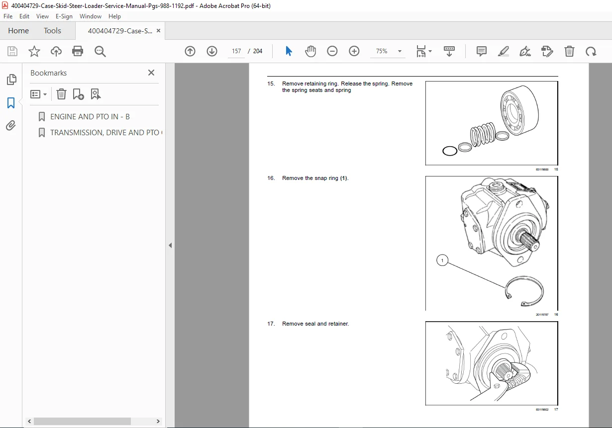
High Pressure Relief Valve:
- Removal Procedures (all EH models):
- Pressure relief before service
- Valve extraction techniques
- Component inspection
- Installation Procedures:
- New O-ring requirements
- Torque specifications
- Pressure verification after installation
Low Pressure Relief Valve:
- Removal Procedures (all EH models):
- Charge pressure system isolation
- Safe removal techniques
- Installation Procedures:
- Seal replacement requirements
- Proper adjustment settings
Pump Adjustments:
Servo Piston Centering Spring Adjustment:
- Mechanical control models only
- Centering spring tension verification
- Neutral position calibration
- Machine creep elimination
Travel Adjustment (Stopping Machine Creep):
- Step-by-step calibration procedures
- Control linkage adjustment
- Neutral band setting
- Verification testing
KEY TECHNICAL FEATURES
✓ 12 model variations covered – SR, SV, TR series loaders
✓ Complete engine removal/installation procedures with torque specs
✓ Fuel system diagnostics including sender and solenoid service
✓ Glow plug system operation and cold start procedures
✓ Ignition switch diagnostic flowchart with 10 test points
✓ Multiple hydrostatic pump specifications (35cc, 46cc, 53cc)
✓ Drive motor specifications (325cc, 470cc single/2-speed)
✓ Pressure testing procedures for hydraulic systems
✓ Relief valve service (high and low pressure)
✓ Solenoid replacement for electro-hydraulic systems
✓ Safety warnings for fuel, hydraulic, and electrical hazards
✓ Wire color codes and connector identification
✓ Detailed illustrations for every procedure
WHO NEEDS THIS MANUAL?
- Heavy Equipment Technicians servicing Case skid steers and track loaders
- Construction Fleet Maintenance Departments maintaining loader equipment
- Case Construction Dealerships performing warranty and repair work
- Equipment Rental Companies servicing rental fleet loaders
- Agricultural Mechanics working with Case compact equipment
- Municipal/Government Fleet Shops maintaining public works equipment
- Technical Training Programs teaching loader repair and maintenance
- Independent Heavy Equipment Repair Shops servicing Case machines
CRITICAL SYSTEMS COVERED
Engine Systems:
- Diesel engine removal and installation
- Fuel injection system components
- Air intake and filtration
- Engine cooling circuits
- Starting and glow plug systems
- Remote oil filtration
Electrical Systems:
- Starter motor connections
- Alternator integration
- Temperature and pressure senders
- Ignition switch diagnostics
- Backfeed diode testing
- Wire harness routing
- Ground connections
Hydraulic Drive Systems:
- Hydrostatic transmission pumps
- Variable displacement controls
- Drive motors (wheel and track)
- Relief valve calibration
- Solenoid valve service
- Pressure testing protocols
- Charge pressure systems
Control Systems:
- Mechanical hydraulic controls
- Electro-hydraulic (EH) controls
- Joystick/hand control integration
- Foot control pedals
- Electronic control modules (where applicable)
EQUIPMENT SPECIFICATIONS INCLUDED
The manual provides detailed specifications for:
Hydraulic Pumps:
- Displacement volumes (35cc, 46cc, 53cc, 63cc)
- Operating pressures (charge and system)
- Relief valve settings (24-385 bar range)
- Shaft speeds and rotation direction
- Port identification and sizing
- Manufacturer part numbers (Sauer-Danfoss, Rexroth)
Drive Motors:
- Displacement volumes (325cc, 470cc)
- Single-speed and 2-speed configurations
- Pressure ratings
- Torque output specifications
- Speed ranges
Electrical Systems:
- Voltage specifications (12V systems)
- Wire gauge and color codes
- Connector pin assignments
- Diode specifications
- Resistance values
SPECIALIZED PROCEDURES
Hydrostatic Transmission Diagnostics:
- Creep adjustment to eliminate unwanted movement
- Neutral position calibration
- Servo piston centering
- Swashplate angle verification
- Control linkage adjustment
Pressure Testing:
- Ground drive system pressure verification
- Relief valve setting confirmation
- Charge pressure testing
- System leak detection
- Test port locations and procedures
Safety Compliance:
- Fire hazard prevention during fuel service
- Hydraulic fluid injection injury prevention
- Electrical shock hazards
- Proper lifting and support procedures
- Personal protective equipment requirements
Stop relying on incomplete online guides and generic repair manuals! This official Case Construction factory service manual provides instant access to model-specific engine procedures, detailed hydrostatic transmission specifications, complete electrical diagnostics, and professional hydraulic system testing protocols. Download now and service your Case skid steer or track loader with the same technical documentation used by certified Case dealerships and factory-trained technicians. Get your equipment back in operation with confidence using factory-authorized repair procedures!
(Pricing rationale: This is a comprehensive 204-page section of the factory service manual covering 12 different Case Construction models across three product series. The manual includes two major technical sections (Engine/PTO and Transmission/Drive) with extensive specifications for multiple pump types (35cc, 46cc, 53cc), motor configurations, and both mechanical and electro-hydraulic control systems. The detailed diagnostic procedures, pressure testing protocols, and model-specific removal/installation sequences justify professional pricing. Case Construction equipment service manuals typically command $34.95-$49.95, with multi-model coverage and hydrostatic system specifications supporting the $39.95 price point.)