Case SV Series Vibratory Rollers Service Manual 7-29532 – PDF DOWNLOAD
Original price was: $89.95.$32.95Current price is: $32.95.
Case SV Series Vibratory Rollers Service Manual 7-29532 – PDF DOWNLOAD
Description
Case SV Series Vibratory Rollers Service Manual 7-29532 – PDF DOWNLOAD
DESCRIPTION:
Case SV Series Vibratory Rollers Service Manual 7-29532 – PDF DOWNLOAD
INTRODUCTION :
This series of Vibratory Rollers is suitable for compaction of all kinds of ground and for large and averagescale site pretaration in highway construction (construction of highways, railways, airports), in hydro-engineering (construction of dams), in building construction (industrial areas, ports), and the like.
- These machines are manufactured in compliance with the latest developments and standards, which ensure their safe function. lf the machine is used incorrectly, by untrained operators or for other purposes than those stipulated within, there is a danger of an accident or damage to the equipment or injury to personnel. SV208 – SV210 / SV212- SV216 / SV223 – SV228 The main purpose of this manual is to give the information necessary for carrying out assembly and disassembly of the machine as well as service repairs of main assemblies of the equipment.
- lt contains technical and installation data, instructions on how to adjust the machine and how to use special toeis, fixtures and aids. The manufacturer continuously seeks to make product improvements on the basis of experience and latest developments in the field. For this reason, the manufacturer may make some changes in drawings, descriptions and designs in this manual
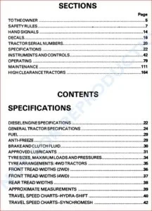
TABLE OF CONTENTS:
Case SV Series Vibratory Rollers Service Manual 7-29532 – PDF DOWNLOAD
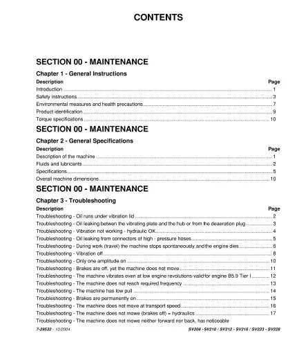
SECTION 00 – MAINTENANCE
Chapter 1 – General lnstructions
Description Page
lntroduction …………………………………………………………………………………………………………………………………….. 1
Safety instructions ……………………………………………………………………………………………………………………………. 3
Environmental measures and health precautions …………………………………………………………………………………. 7
Product identification ………………………………………………………………………………………………………………………… 9
Torque specifications ……………………………………………………………………………………………………………………… 1 O
SECTION 00 – MAINTENANCE
Chapter 2 – General Specifications
Description Page
Description of the machine ……………………………………………………………………………………………………………….. 1
Fluids and lubricants ………………………………………………………………………………………………………………………… 2
Specifications ………………………………………………………………………………………………………………………………….. 5
Overall machine dimensions ……………………………………………………………………………………………………………. 1 O
SECTION 00 – MAINTENANCE
Chapter 3 – Troubleshooting
Description Page
Troubleshooting – Oil runs under vibration lid ………………………………………………………………………………………. 2
Troubleshooting – Oil leaking betwen the vibrating pia te and the hub or from the deaeration plug ………………. 3
Troubleshooting – Vibration not working – hydraulic OK …………………………………………………………………………. 4
Troubleshooting – Oil leaking from connectors of high – pressure hoses ………………………………………………….. 5
Troubleshooting – During work (travei) the machine stops spontaneously and the engine dies …………………… 6
Troubleshooting – Vibration off …………………………………………………………………………………………………………… 8
Troubleshooting – Only one amplitude on ………………………………………………………………………………………….. 1 O
Troubleshooting – Brakes are off, yet the machine does not move ………………………………………………………… 11
Troubleshooting – The machine vibrates even at low engine revolutions-valid for engine B5.9 Tier 1 ••••••••••••• 12
Troubleshooting – The machine does not reach required frequency ……………………………………………………… 13
Troubleshooting – The machine has low pull ……………………………………………………………………………………… 14
Troubleshooting – Brakes are permanently on ……………………………………………………………………………………. 15
Troubleshooting – The machine does not move at transport speed ……………………………………………………….. 16
Troubleshooting – The machine does not mowe (brakes off) = hydraulics ……………………………………………… 17
Troubleshooting – The machine does not mowe neither forward nor back, has noticeable
7-29532 – 10/2004 SV208 – SV210 / SV212 – SV216 / SV223 – SV228
2 CONTENTS
low pull in one direction …………………………………………………………………………………………………………………… 18
Troubleshooting – ASC does not work – 2 valves ………………………………………………………………………………… 19
Troubleshooting – ASC does not work – 4 valves ………………………………………………………………………………… 20
Troubleshooting – Steering is defective, the wheel gets stucks …………………………………………………………….. 21
Troubleshooting – Steering does not work in difficult terrain …………………………………………………………………. 22
Troubleshooting – Steering goes to one side ……………………………………………………………………………………… 23
Troubleshooting – The machine’s brackes stay on when the steering wheel is turned ……………………………… 24
Troubleshooting – After starting, the machine’s brakes remain on ………………………………………………………… 25
Troubleshooting – Oil leak from hydraulic system ……………………………………………………………………………….. 26
Troubleshooting – Hydraulic oil foams up …………………………………………………………………………………………… 27
Troubleshooting – Hydraulic oil is too hot.. …………………………………………………………………………………………. 28
Troubleshooting – The machine cannot be started ……………………………………………………………………………… 29
SECTION 00 – GENERAL INSTRUCTION
Chapter 4 – Special service tools
Description Page
Tools and equipment ……………………………………………………………………………………………………………………….. 1
7-29532 – 10/2004 SV208 – SV210 / SV212 – SV216 / SV223 – SV228
CONTENTS 3
SECTION 1 O – ENGINE
Chapter 1 – Removal and installation
Description Page
Specifications ………………………………………………………………………………………………………………………………….. 2
Description ……………………………………………………………………………………………………………………………………… 3
Torque specifications ……………………………………………………………………………………………………………………….. 5
Special too Is ……………………………………………………………………………………………………………………………………. 5
Removal …………………………………………………………………………………………………………………………………………. 7
1 nstallation …………………………………………………………………………………………………………………………………….. 14
Accelerator cable assembly removal and installation ………………………………………………………………………….. 14
SECTION 21 – TRANSMISSION
Chapter 1 – Hydraulic motor
Description Page
Description ……………………………………………………………………………………………………………………………………… 2
Specifications ………………………………………………………………………………………………………………………………….. 3
Torque specifications ……………………………………………………………………………………………………………………….. 3
Disassembly ……………………………………………………………………………………………………………………………………. 3
Reconditioning and replacement ……………………………………………………………………………………………………….. 5
Assembly ……………………………………………………………………………………………………………………………………….. 8
SECTION 21 – TRANSMISSION
Chapter 2 – Travei reduction gear
Description Page
Specification ……………………………………………………………………………………………………………………………………. 1
Torque specifications ……………………………………………………………………………………………………………………….. 2
Special too Is ……………………………………………………………………………………………………………………………………. 2
Exploded view of travei brake ……………………………………………………………………………………………………………. 6
Disassembly and assembly ………………………………………………………………………………………………………………. 7
Brake test ……………………………………………………………………………………………………………………………………….. 9
Exploded view ……………………………………………………………………………………………………………………………….. 1 O
Disassembly and assembly …………………………………………………………………………………………………………….. 11
SECTION 29 – HVDROSTATIC DRIVE
Chapter 1 – Pumps – drive coupling
Description Page
Specifications ………………………………………………………………………………………………………………………………….. 1
Torque specifications ……………………………………………………………………………………………………………………….. 1
Description ……………………………………………………………………………………………………………………………………… 2
Special too Is ……………………………………………………………………………………………………………………………………. 3
Removal of pumps, clutch …………………………………………………………………………………………………………………. 3
Drive coupling …………………………………………………………………………………………………………………………………. 7
SV208 – SV210 / SV212- SV216 / SV223 – SV228 7-29532 – 10/2004
4 CONTENTS
SECTION 35 – HVDRAULIC SYSTEM
Chapter 1 – Hydraulic cylinders for Cab and Hood
Description Page
Torque Specifications ………………………………………………………………………………………………………………………. 1
Description ……………………………………………………………………………………………………………………………………… 2
Special too Is ……………………………………………………………………………………………………………………………………. 3
Hood hydraulic cylinders …………………………………………………………………………………………………………………… 5
Cab hydraulic cylinder ………………………………………………………………………………………………………………………. 7
Hydraulic cylinders …………………………………………………………………………………………………………………………… 7
SECTION 35 – HVDRAULIC SYSTEM
Chapter 2 – Vibration Motor
Description Page
Specifications ………………………………………………………………………………………………………………………………….. 1
Torque specifications ……………………………………………………………………………………………………………………….. 1
Description ……………………………………………………………………………………………………………………………………… 2
Disassembly ……………………………………………………………………………………………………………………………………. 3
Assembly ……………………………………………………………………………………………………………………………………….. 8
Supply pressure relief valve adjustment ……………………………………………………………………………………………. 12
SECTION 35 – HVDRAULIC SYSTEM
Chapter 3 – Hydraulic circuit
Description Page
Hydraulic installation ………………………………………………………………………………………………………………………… 2
Functional description ………………………………………………………………………………………………………………………. 2
Travei without activation …………………………………………………………………………………………………………………… 3
Travei activated, moving forward ……………………………………………………………………………………………………….. 4
The multi-function valve ……………………………………………………………………………………………………………………. 5
The idler-wheel lock-block on the flow divider ……………………………………………………………………………………… 6
ASC valve ………………………………………………………………………………………………………………………………………. 7
Vibration hydraulics ………………………………………………………………………………………………………………………….. 8
Vibration without activation ……………………………………………………………………………………………………………….. 8
Vibration activated …………………………………………………………………………………………………………………………. 1 O
Steering hydraulics ………………………………………………………………………………………………………………………… 12
Steering without activation ………………………………………………………………………………………………………………. 13
Steering to the right. ……………………………………………………………………………………………………………………….. 14
Lifting hydraulics ……………………………………………………………………………………………………………………………. 15
Lifting of the cab or hood ………………………………………………………………………………………………………………… 16
Lowering the cab and hood ……………………………………………………………………………………………………………… 17
Reservoir hydraulics ………………………………………………………………………………………………………………………. 18
Hydraulic reservo ir …………………………………………………………………………………………………………………………. 18
Discharging of closed circuits ………………………………………………………………………………………………………….. 19
Brake release – emergency towing …………………………………………………………………………………………………… 20
Test points ……………………………………………………………………………………………………………………………………. 21
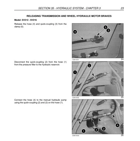
Releasing transmission and wheel hydraulic motor brakes ………………………………………………………………….. 23
7-29532 – 10/2004 SV208 – SV210 / SV212 – SV216 / SV223 – SV228
CONTENTS 5
Hydraulic diagram SV208 – SV21 O two valves ASC ……………………………………………………………………………. 28
Hydraulic diagram SV208 – SV21 O 4 valves ASC ……………………………………………………………………………….. 30
Hydraulic diagram SV212 – SV216 two valves ASC ……………………………………………………………………………. 32
Hydraulic diagram SV212 – SV216 4 valves ASC ……………………………………………………………………………….. 34
Hydraulic diagram SV223 – SV228 two valves ASC ……………………………………………………………………………. 36
Hydraulic diagram SV223 – SV228 4 valves ASC ……………………………………………………………………………….. 38
SECTION 35 – HVDRAULIC SYSTEM
Chapter 4 – Hydraulic pump
Description Page
Specifications ………………………………………………………………………………………………………………………………….. 1
Torque specifications ……………………………………………………………………………………………………………………….. 1
Description ……………………………………………………………………………………………………………………………………… 2
Disassembly ……………………………………………………………………………………………………………………………………. 3
Reconditioning and replacement of parts ……………………………………………………………………………………………. 8
Assembly ……………………………………………………………………………………………………………………………………… 14
lnspection and adjustments …………………………………………………………………………………………………………….. 26
SECTION 39 – FRAMES
Chapter 1 – Drum
Description Page
Description ……………………………………………………………………………………………………………………………………… 2
Specifications ………………………………………………………………………………………………………………………………….. 6
Torque specifications ……………………………………………………………………………………………………………………….. 6
Special too Is ……………………………………………………………………………………………………………………………………. 7
Drum removal ……………………………………………………………………………………………………………………………….. 11
Vibrator pi ate assembly ………………………………………………………………………………………………………………….. 21
Removal of the right side of the drum ……………………………………………………………………………………………….. 23
Removing the rubber mounting on SV223 – SV228 …………………………………………………………………………….. 29
lnspection and adjustment of vibration frequency ……………………………………………………………………………….. 31
Adjusting Max revolution …………………………………………………………………………………………………………………. 33
SECTION 39 – FRAMES
Chapter 2 – Articulation
Description Page
Specifications ………………………………………………………………………………………………………………………………….. 1
Torque specifications ……………………………………………………………………………………………………………………….. 1
Description ……………………………………………………………………………………………………………………………………… 2
Special too Is ……………………………………………………………………………………………………………………………………. 4
Disassembly ……………………………………………………………………………………………………………………………………. 6
SECTION 39 – FRAMES
Chapter 3 – Drum Segments and Scrapers
Description Page
Specifications ………………………………………………………………………………………………………………………………….. 1
Hardware torque ……………………………………………………………………………………………………………………………… 1
SV208 – SV210 / SV212- SV216 / SV223 – SV228 7-29532 – 10/2004
6 CONTENTS
Special too Is ……………………………………………………………………………………………………………………………………. 1
Description ……………………………………………………………………………………………………………………………………… 2
Segment installation on smoothdrum unit ……………………………………………………………………………………………. 3
7-29532 – 10/2004 SV208 – SV210 / SV212 – SV216 / SV223 – SV228
CONTENTS 7
SECTION 41 – STEERING
Chapter 1 – Control
Description Page
Specifications ………………………………………………………………………………………………………………………………….. 1
Special too Is ……………………………………………………………………………………………………………………………………. 1
Description ……………………………………………………………………………………………………………………………………… 2
Troubleshooting – steering ………………………………………………………………………………………………………………… 3
Disassembly and assembly of steering wheel ……………………………………………………………………………………… 3
SECTION 41 – STEERING
Chapter 2 – Steering cylinders
Description Page
Special torques ……………………………………………………………………………………………………………………………….. 1
Special too Is ……………………………………………………………………………………………………………………………………. 2
Removal of steering cylinders ……………………………………………………………………………………………………………. 3
Replacing the seals ………………………………………………………………………………………………………………………….. 4
SECTION 41 – STEERING
Chapter 3 – Steering control valve
Description Page
Specifications ………………………………………………………………………………………………………………………………….. 1
Tightening torques …………………………………………………………………………………………………………………………… 1
Description ……………………………………………………………………………………………………………………………………… 2
Special too Is ……………………………………………………………………………………………………………………………………. 3
Disassembly ……………………………………………………………………………………………………………………………………. 4
Checking the steering elements …………………………………………………………………………………………………………. 7
Reassembly ……………………………………………………………………………………………………………………………………. 7
SECTION 44 – WHEELS
Chapter 1 – Removal and installation
Description Page
Specification ……………………………………………………………………………………………………………………………………. 1
Torque specification …………………………………………………………………………………………………………………………. 1
Special tool …………………………………………………………………………………………………………………………………….. 1
Description ……………………………………………………………………………………………………………………………………… 2
Disassembly of wheel ………………………………………………………………………………………………………………………. 3
Assembly ……………………………………………………………………………………………………………………………………….. 3
SECTION 50 – HEATER -AIR-CONDITIONING
Chapter 1 – Removal and installation
Description Page
Specifications ………………………………………………………………………………………………………………………………….. 1
Removal …………………………………………………………………………………………………………………………………………. 2
Air-conditioning system defects …………………………………………………………………………………………………………. 4
Replacing (tightening) the belt …………………………………………………………………………………………………………… 5
SV208 – SV210 / SV212- SV216 / SV223 – SV228 7-29532 – 10/2004
8 CONTENTS
SECTION 55 – ELECTRICAL CIRCUIT
Chapter 1 – Wiring diagram
Description Page
Electrical installation ………………………………………………………………………………………………………………………… 1
Functional description ………………………………………………………………………………………………………………………. 7
Electrical legend ………………………………………………………………………………………………………………………………. 9
SECTION 90 – PLATFORM, CAB
Chapter 1 – Operator’s compartment
Description Page
Torque specifications ……………………………………………………………………………………………………………………….. 1
Operator’s compartment …………………………………………………………………………………………………………………… 2
Travei brake contrai adjustment. ………………………………………………………………………………………………………… 8
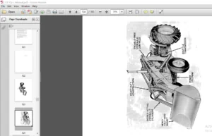
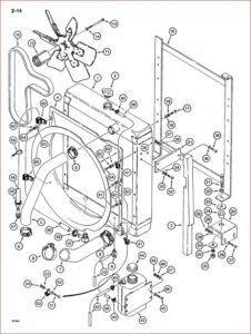
IMAGES PREVIEW OF THE MANUAL:
CASE SV SERIES VIBRATORY ROLLERS SERVICE MANUAL 7-29532 – PDF DOWNLOAD:
PLEASE NOTE:
- This is the SAME exact manual used by your dealers to fix your vehicle.
- The same can be yours in the next 2-3 mins as you will be directed to the download page immediately after paying for the manual.
- Any queries / doubts regarding your purchase, please feel free to contact [email protected]
S.V