Case TX130-30 TX130-30 turbo TX130-33 TX130-33 turbo Telehandler Workshop Manual 9-93210 – PDF
Original price was: $89.95.$29.95Current price is: $29.95.
Case TX130-30 TX130-30 turbo TX130-33 TX130-33 turbo Telehandler Workshop Manual 9-93210 – PDF DOWNLOAD
Description
Case TX130-30 TX130-30 turbo TX130-33 TX130-33 turbo Telehandler Workshop Manual 9-93210 – PDF DOWNLOAD
IMAGES PREVIEW OF THE MANUAL:
DESCRIPTION:
Case TX130-30 TX130-30 turbo TX130-33 TX130-33 turbo Telehandler Workshop Manual 9-93210 – PDF DOWNLOAD
GENERAL INSTRUCTIONS :
IMPORTANT NOTICE :
All maintenance and repair interventions listed in this Manual must be performed exclusively by the Service
Network of the Manufacturer, complying strictly with the indications herein and using, when required, the
prescribed special tools.
Whoever performs service operations described herein without complying strictly with the instructions becomes
solely responsible for any consequential damage that could occur.
ADJUSTING SHIMS :
For each adjustment select the adjusting shims, measuring them one by one with a micrometer and adding to
gether subsequently, the values measured. Do not rely on the measurement of the entire pack, that could be
wrong, or the nominal value indicated on each ring.
SEALS FOR ROTATING SHAFTS :
For correct installation of the seals for rotating shafts, please comply with the following precautions:
— prior to installation, keep the seals soaking for at least half an hour in the same oil they are going to seal;
— clean thoroughly the shaft and make sure that its working face is undamaged;
— direct the sealing lip toward the fluid; in the event the lip is of the hydro dynamic type, the grooves must be
directed so that, in relation to the rotating direction of the shaft, they tend to return the fluid toward the inside
of the sealing device;
— smear the sealing lip with a film of lubricant (oil to be preferred to grease) and fill with grease the gap between
sealing lip and dust lip in twin lip seals;
— insert the seal in its seat, pressing it with a punch with a flat face; never strike it with a hammer or mallet;
— when pressing in the seal, make sure that it is inserted perpendicularly in relation to the seat and, once in
position, make sure that, when required, it contacts the shoulder;
— to prevent the sealing lip of the seal being damaged by the shaft, insert appropriate protection during the
installation of the two parts.
TABLE OF CONTENTS:
Case TX130-30 TX130-30 turbo TX130-33 TX130-33 turbo Telehandler Workshop Manual 9-93210 – PDF DOWNLOAD
SECTION 00 — GENERAL
Description Page
General instructions 1
Safety rules 3
Product identification 6
Environmental considerations 9
Maintenance techniques 10
SECTION 10 — ENGINE
Description Page
Main specifications of engines 2
Troubleshooting 5
Generalities engine F4GE0404B*D600 21
Generalities engine F4GE0454C*D600 23
Description of main mechanical components of the engine 25
Lubrication 37
Cooling 42
Mechanical injection supply system 44
Mechanical fuel pump 45
Injection assembly 46
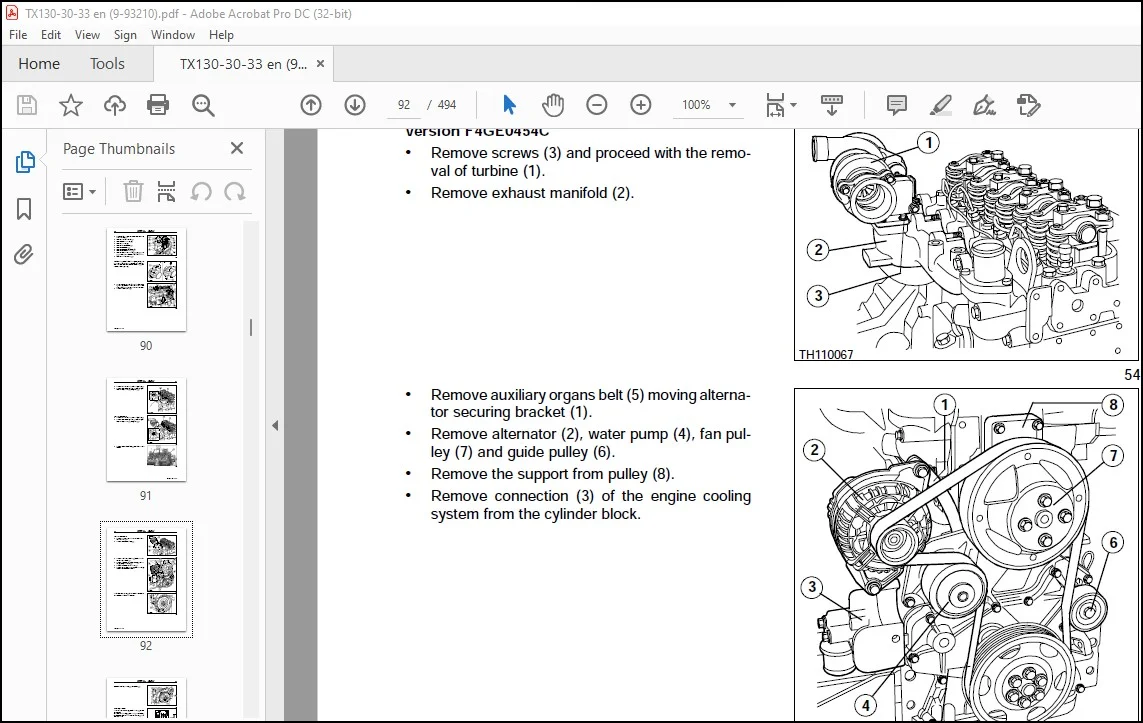
Removal of engine transmission group from the vehicle 56
Engine overhaul on bench 59
Repair interventions on the cylinder group 71
Timing 73
Bushes 74
Crankshaft 77
Conrod–piston assembly 81
Valves 103
Valve guides 104
Valve seats 104
Valve springs 106
Assembly of cylinder head 106
Replacing the injectors 113
Adjustment of valve clearance 115
Removal/reinstallation of rocker arms 115
Setting of timing 116
4 GENERAL LIST OF CONTENTS
9-93210 — 12 — 2004
Timing of the injection pump 117
Electrical components 118
Tooling 119
SECTION 21 — POWERSHIFT GEARBOX
Description Page
Powershift Gearbox 4×4 2
Driving with the powershift gearbox 2
Gearbox assembly 5
Idler gear case assembly 7
Gearbox operation 8
Transmission and Hydraulic oil circuit diagrams 15
Modulation valve operation 31
Torque converter and heat exchanger hydraulic oil circuit 34
Troubleshooting guide 35
Troubleshooting procedures 35
Troubleshooting 37
Pressure testing clutch and high pressure circuit 38
Pressure testing torque converter and cooler circuit 39
Check points 40
Assembly instructions 42
Overhaul 45
Special tools 104
SECTION 25 — FRONT AXLE
Description Page
Specifications 1
Description 2
Operation 3
Troubleshooting 4
Wheel toe–in check 5
Component overhaul 5
Front axle removal procedure 6
Front axle overhaul 7
Axle drive pinion bearing adjustment 52
How to install and adjust the axle drive pinion 54
Front drive shaft 57
SECTION 27 — REAR AXLE
Description Page
Specifications 1
Description 2
GENERAL LIST OF CONTENTS 5
9-93210 — 12 — 2004
Operation diagram 3
Component overhaul 5
Rear axle removal procedure 5
Overhaul 6
Special tools 7
SECTION 33 — BRAKES
Description Page
Specifications 1
Power brakes 2
Parking brake 3
Brake disc adjustment 6
Troubleshooting 7
Brakes disassembly 8
SECTION 35 — HYDRAULIC SYSTEM
Description Page
Technical data 2
Description and operation 3
Introduction 3
Steering system hydraulic circuit 3
Steering valve 4
Telescopic boom hydraulic circuit 6
Component operation 10
Hydraulic pump 10
Delivery side divider valve 10
Pressure reduction valve 12
Front loader controls 14
Balancing valves 16
Power steering (OSPQ) 18
Telescopic boom distributor 19
Auxiliary control distributor 22
Cylinders 24
Booms 34
SECTION 55 — ELECTRICAL SYSTEM
Description Page
Chapter 1 – Electrical system general
Electrical equipment specifications 1
Electrical system and fuses 2
Controls and instruments 6
Procedure for the calibration of the load momentum system 17
6 GENERAL LIST OF CONTENTS
9-93210 — 12 — 2004
Bulb replacement 22
Protecting the electrical systems during charging or welding 25
Starting the machine using jump leads 26
Temporary wiring repairs 27
Electrical system–general fault finding 29
Chapter 2 – Circuit diagrams
List of connectors 32
List of components 33
How to use the circuit diagrams 34
Diagram 1: Starting/Recharge/Warning/Indicators lights 36
Diagram 2: Transmission 38
Diagram 3: Wheel alignment/Hydraulic solenoids/Brake system 40
Diagram 4: Boom control 42
Diagram 5: Stabiliser 44
Diagram 6: Lights/Front wiper 46
Diagram 7: Work lamps/Roof beacon light 48
Diagram 8: Load momentum device / Upper wiper 50
Diagram 9: Heating / Radio / Power socket / Ceiling light 52
Diagram 10: Conditioner 54
Chapter 3 — Wiring list
Instrument panel wiring 58
Cab wiring 62
Front wiring 63
Rear wiring 64
Engine wiring 65
SECTION 60 — AIR CONDITIONING UNIT
Description Page
AIR CONDITIONING UNIT 2
Operating instructions 2
Cab climate 4
Cab climate controls 4
Air conditioning system 5
Service precautions 6
Tool connections 9
Discharging 10
Refrigerant charging 10
Leak inspection 11
Special tools 14
Troubleshooting 15
Need help? Contact: [email protected]
PLEASE NOTE:
- This is the SAME MANUAL used by the dealerships to diagnose your vehicle
- No waiting for couriers / posts as this is a PDF manual and you can download it within 2 minutes time once you make the payment.
- Your payment is all safe and the delivery of the manual is INSTANT – You will be taken to the DOWNLOAD PAGE.
- So have no hesitations whatsoever and write to us about any queries you may have : heydownloadss @gmail.com
S.V