Case TX130-40 TX130-43 TX130-45 TX140-43 TX140-45 TX170-45 Telehandlers Service Manual 87682529B – PDF DOWNLOAD
Original price was: $89.95.$28.95Current price is: $28.95.
Case TX130-40 TX130-43 TX130-45 TX140-43 TX140-45 TX170-45 Telehandlers Service Manual 87682529B – PDF DOWNLOAD
Description
Case TX130-40 TX130-43 TX130-45 TX140-43 TX140-45 TX170-45 Telehandlers Service Manual 87682529B – PDF DOWNLOAD
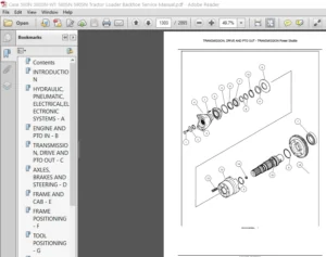
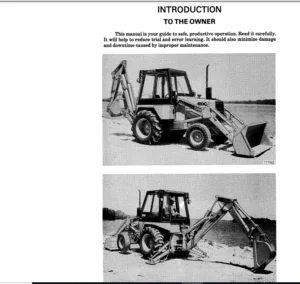
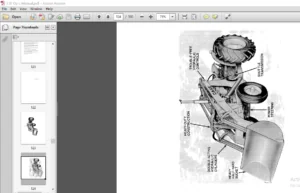
IMAGES PREVIEW OF THE MANUAL:
DESCRIPTION:
Case TX130-40 TX130-43 TX130-45 TX140-43 TX140-45 TX170-45 Telehandlers Service Manual 87682529B – PDF DOWNLOAD
GENERAL INSTRUCTIONS
IMPORTANT NOTICE
All maintenance and repair interventions listed in this Manual must be performed exclusively by the Service
Network of the Manufacturer, complying strictly with the indications herein and using, when required, the
prescribed special tools.
Whoever performs service operations described herein without complying strictly with the instructions becomes
solely responsible for any consequential damage that could occur.
ADJUSTING SHIMS
For each adjustment select the adjusting shims, measuring them one by one with a micrometer and adding to
gether subsequently, the values measured. Do not rely on the measurement of the entire pack, that could be
wrong, or the nominal value indicated on each ring.
SEALS FOR ROTATING SHAFTS
For correct installation of the seals for rotating shafts, please comply with the following precautions:
— prior to installation, keep the seals soaking for at least half an hour in the same oil they are going to seal;
— clean thoroughly the shaft and make sure that its working face is undamaged;
— direct the sealing lip toward the fluid; in the event the lip is of the hydro dynamic type, the grooves must be
directed so that, in relation to the rotating direction of the shaft, they tend to return the fluid toward the inside
of the sealing device;
— smear the sealing lip with a film of lubricant (oil to be preferred to grease) and fill with grease the gap between
sealing lip and dust lip in twin lip seals;
— insert the seal in its seat, pressing it with a punch with a flat face; never strike it with a hammer or mallet;
— when pressing in the seal, make sure that it is inserted perpendicularly in relation to the seat and, once in
position, make sure that, when required, it contacts the shoulder;
— to prevent the sealing lip of the seal being damaged by the shaft, insert appropriate protection during the
installation of the two parts.
TABLE OF CONTENTS:
Case TX130-40 TX130-43 TX130-45 TX140-43 TX140-45 TX170-45 Telehandlers Service Manual 87682529B – PDF DOWNLOAD
SECTION 00 — GENERAL
Description Page
General instructions 1
Safety rules 3
Product identification 6
Environmental considerations 9
Maintenance techniques 10
SECTION 10 — ENGINE
Description Page
Main specifications of engine 3
General engine specification 4
Generalities engine F4GE9484J*J600 6
Removal and installation of the motor and the radiator 11
Troubleshooting 23
Tightening torques 36
4 GENERAL LIST OF CONTENTS
SECTION 21 — POWERSHIFT GEARBOX
Description Page
Gearbox assembly 5
Idler gear case assembly 7
Gearbox operation 8
Transmission and Hydraulic oil circuit diagrams 15
Modulation valve operation 31
Torque converter and heat exchanger hydraulic oil circuit 34
Troubleshooting procedures 37
Pressure testing clutch and high pressure circuit 38
Pressure testing torque converter and cooler circuit 39
Check points 40
Assembly instructions 42
Overhaul 45
Special tools 104
SECTION 25 — FRONT AXLE
Description Page
Specifications 1
Description 2
Operation 3
Troubleshooting 4
Wheel toe–in check 5
Component overhaul 5
Front axle removal procedure 6
Front axle overhaul 7
Axle drive pinion bearing adjustment 52
How to install and adjust the axle drive pinion 54
Front drive shaft 57
GENERAL LIST OF CONTENTS 5
SECTION 27 — REAR AXLE
Description Page
Specifications 1
Description 2
Operation diagram 3
Component overhaul 5
Rear axle removal procedure 5
Overhaul 6
Special tools 7
SECTION 33 — BRAKES
Description Page
Power brakes 2
Parking brake 3
Brake disc adjustment 6
Troubleshooting 7
Brake disc replacement 8
SECTION 35 — HYDRAULIC SYSTEM
Description Page
Technical data 2
Description and operation 3
Steering system hydraulic circuit 3
Steering valve 4
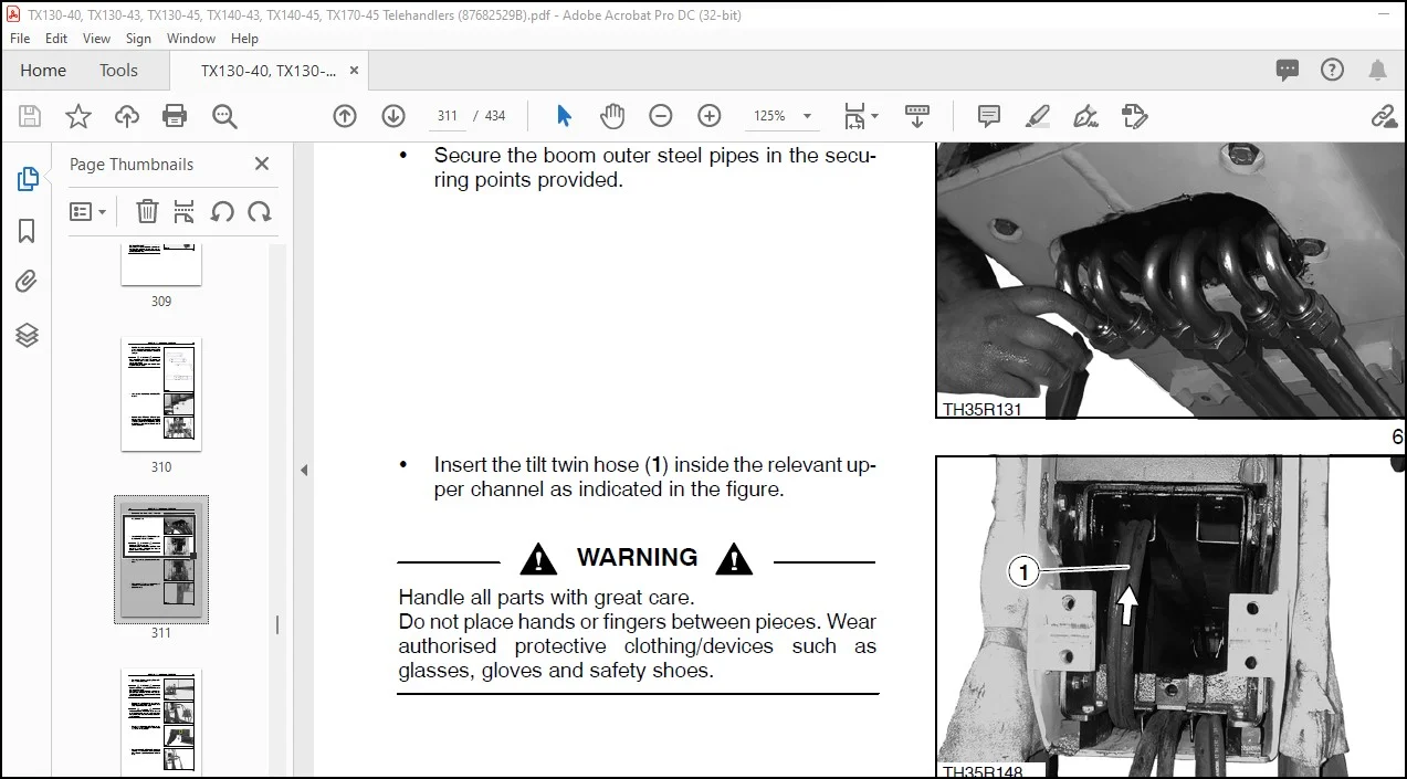
Telescopic boom hydraulic circuit 6
Component operation 11
Hydraulic pump 11
Hydraulic scheme 11
Delivery side divider valve 11
Pressure reducing valve 13
Front loader controls 15
Power steering (OSPQ) 19
Telescopic boom distributor 21
Auxiliary controls distributor 24
Cylinders 25
Arms 35
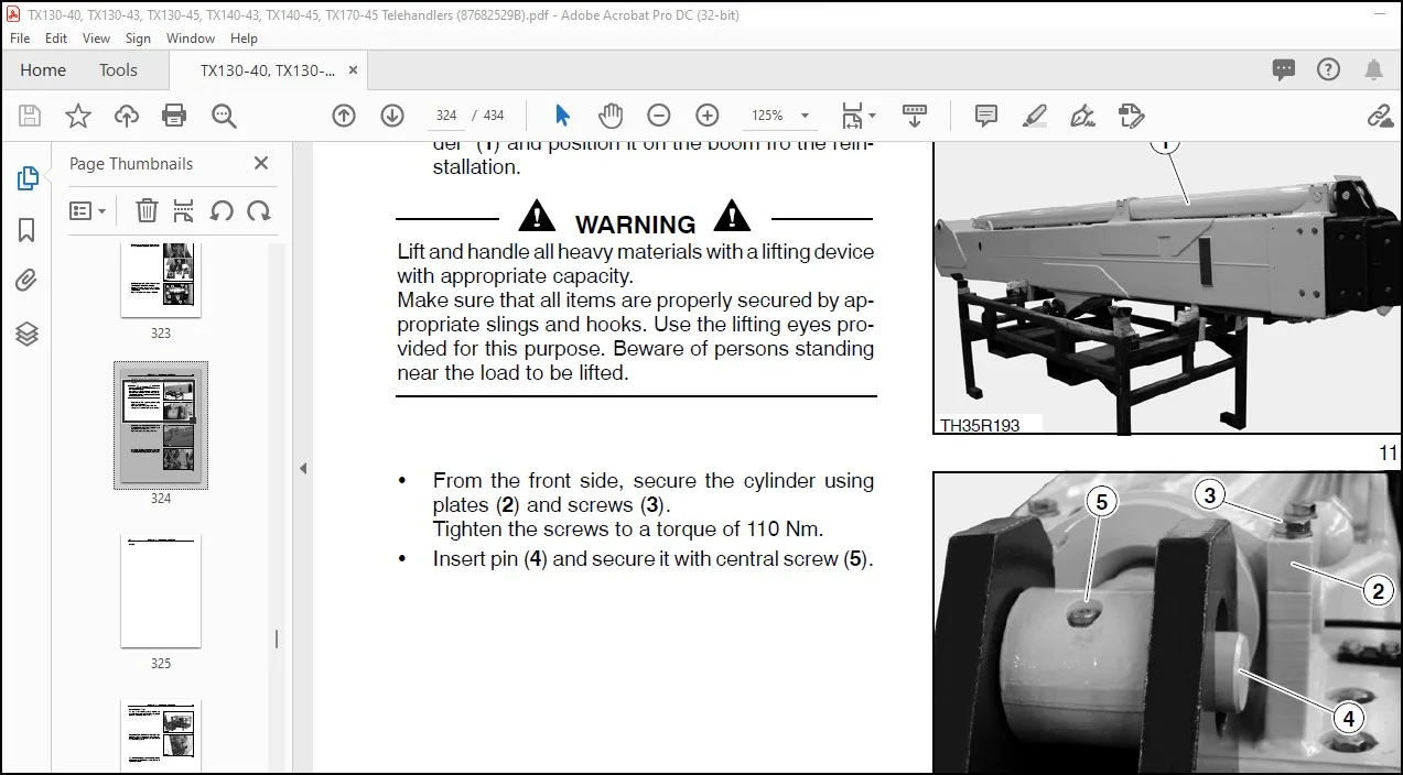
Boom removal 35
Working platform 61
Procedure for the calibration of the personnel carrier platform electronic controller 65
Special tools 71
6 GENERAL LIST OF CONTENTS
SECTION 55 — ELECTRICAL SYSTEM
Description Page
Chapter 1 – Electrical system general
Electrical equipment specifications 1
Electrical system and fuse 2
Controls and instruments 6
SAR — Anti–tipping system 14
Bulb replacement 33
Protecting the electrical systems during charging or welding 36
Starting the machine using jump leads 37
Temporary wiring repair 38
Electrical system general fault finding 40
Working platform 41
Special tools 56
Chapter 2 – Circuit diagrams
List of connectors 58
List of components 59
How to use the circuit diagrams 60
Diagram 1: Starting/Recharge/Warning/Indicators lights 62
Diagram 2: Transmission 64
Diagram 2A: Transmission — France omologation 66
Diagram 3: Wheel alignment/Hydraulic solenoids/Brake system 68
Diagram 4: Boom control 70
Diagram 5: Stabiliser 72
Diagram 6: Lights/Front wiper 74
Diagram 7: Work lamps/Roof beacon light 76
Diagram 8: Upper wiper 78
Diagram 9: Load momentum device 80
Diagram 10: Heating / Radio / Power socket / Ceiling light 82
Diagram 11: Conditioner 84
Chapter 3 — Wiring list
Instrument panel wiring 89
Cab wiring 93
Front wiring 94
Rear wiring 95
Engine wiring 96
Contact us: [email protected]
https://vimeo.com/724457886
PLEASE NOTE:
- This is not a physical manual but a digital manual – meaning no physical copy will be couriered to you. The manual can be yours in the next 2 mins as once you make the payment, you will be directed to the download page IMMEDIATELY.
- This is the same manual used by the dealers inorder to diagnose your vehicle of its faults.
- Require some other service manual or have any queries: please WRITE to us at [email protected]
S.V