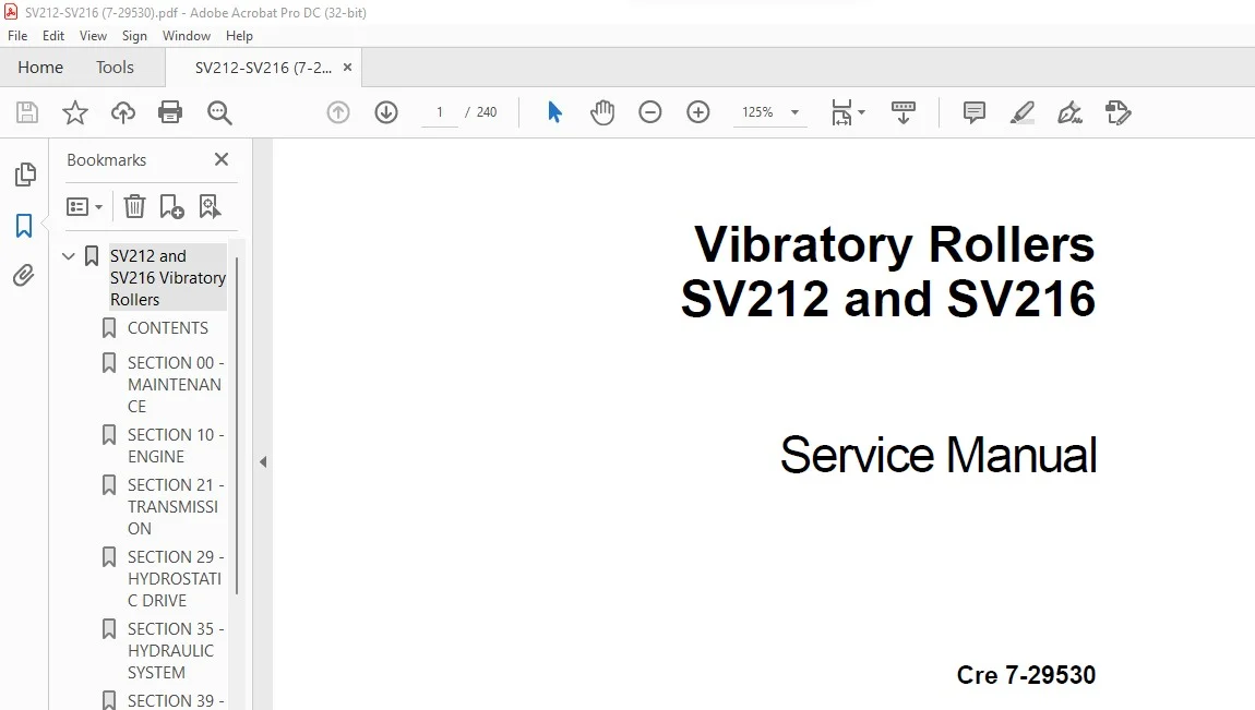
Case Vibratory Rollers SV212 & SV216 Service Manual 7-29530 – PDF DOWNLOAD
Original price was: $89.95.$28.95Current price is: $28.95.
Case Vibratory Rollers SV212 & SV216 Service Manual 7-29530 – PDF DOWNLOAD
Description
Case Vibratory Rollers SV212 & SV216 Service Manual 7-29530 – PDF DOWNLOAD
DESCRIPTION:
Case Vibratory Rollers SV212 & SV216 Service Manual 7-29530 – PDF DOWNLOAD
INTRODUCTION :
- This series of Vibratory Rollers is suitable for compaction of all kinds of ground and for large and averagescale groundwork in highway construction (construction of motorways, railways, aiports), in hydro-engineering (construction of dams), in building construction (industrial areas, ports), and the like.
- These machines are manufactured in conformity with the latest developments and standards, which ensure their safe function. If the machine is used incorrectly, by untrained operators or for other purposes than those stipulated above, there is a danger of an accident or damage to the equipment.
- The main purpose of this manual is to give the information necessary for carrying out assembly and disassembly of the machine as well as service repairs of main assemblies of the equipment.
- It contains technical and installation data, instructions on how to adjust the machine and how to use special tools, fixtures and aids. The manufacturer continuously seeks to make product improvements on the basis of experience and latest developments in the field. For this reason, the manufacturer may make some changes in drawings, descriptions and designs in this manual.
TABLE OF CONTENTS:
Case Vibratory Rollers SV212 & SV216 Service Manual 7-29530 – PDF DOWNLOAD
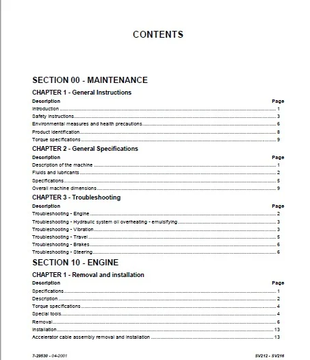
SECTION 00 – MAINTENANCE
CHAPTER 1 – General Instructions
Description Page
Introduction …………………………………………………………………………………………………………………………………….. 1
Safety instructions……………………………………………………………………………………………………………………………. 3
Environmental measures and health precautions…………………………………………………………………………………. 6
Product identification………………………………………………………………………………………………………………………… 8
Torque specifications……………………………………………………………………………………………………………………….. 9
CHAPTER 2 – General Specifications
Description Page
Description of the machine ……………………………………………………………………………………………………………….. 1
Fluids and lubricants ………………………………………………………………………………………………………………………… 2
Specifications………………………………………………………………………………………………………………………………….. 5
Overall machine dimensions……………………………………………………………………………………………………………… 9
CHAPTER 3 – Troubleshooting
Description Page
Troubleshooting – Engine………………………………………………………………………………………………………………….. 2
Troubleshooting – Hydraulic system oil overheating – emulsifying…………………………………………………………… 3
Troubleshooting – Vibration……………………………………………………………………………………………………………….. 3
Troubleshooting – Travel …………………………………………………………………………………………………………………… 5
Troubleshooting – Brakes………………………………………………………………………………………………………………….. 6
Troubleshooting – Steering………………………………………………………………………………………………………………… 6
SECTION 10 – ENGINE
CHAPTER 1 – Removal and installation
Description Page
Specifications………………………………………………………………………………………………………………………………….. 1
Description……………………………………………………………………………………………………………………………………… 2
Torque specifications……………………………………………………………………………………………………………………….. 4
Special tools……………………………………………………………………………………………………………………………………. 4
Removal…………………………………………………………………………………………………………………………………………. 6
Installation…………………………………………………………………………………………………………………………………….. 13
Accelerator cable assembly removal and installation ………………………………………………………………………….. 13
2 CONTENTS
SV212 – SV216 7-29530 – 04-2001
SECTION 21 – TRANSMISSION
CHAPTER 1 – Hydraulic motor
Description Page
Description……………………………………………………………………………………………………………………………………… 2
Specifications………………………………………………………………………………………………………………………………….. 3
Torque specifications……………………………………………………………………………………………………………………….. 3
Disassembly……………………………………………………………………………………………………………………………………. 3
Reconditioning and replacement ……………………………………………………………………………………………………….. 5
Assembly ……………………………………………………………………………………………………………………………………….. 8
CHAPTER 2 – Travel reduction gear
Description Page
Specification……………………………………………………………………………………………………………………………………. 1
Torque specifications……………………………………………………………………………………………………………………….. 2
Special tools……………………………………………………………………………………………………………………………………. 2
Exploded view of travel brake……………………………………………………………………………………………………………. 6
Disassembly and assembly ………………………………………………………………………………………………………………. 7
Brake test……………………………………………………………………………………………………………………………………….. 9
Exploded view……………………………………………………………………………………………………………………………….. 10
Disassembly and assembly …………………………………………………………………………………………………………….. 11
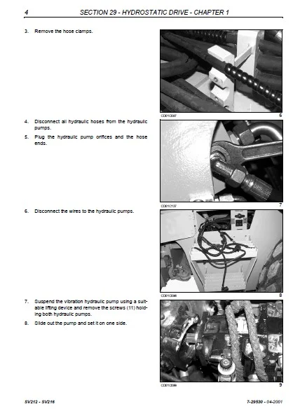
SECTION 29 – HYDROSTATIC DRIVE
CHAPTER 1 – Pumps – Cento drive coupling
Description Page
Specifications………………………………………………………………………………………………………………………………….. 1
Tightening torque…………………………………………………………………………………………………………………………….. 1
Description……………………………………………………………………………………………………………………………………… 2
Special tools……………………………………………………………………………………………………………………………………. 3
Removal of pumps, Cento clutch……………………………………………………………………………………………………….. 3
Cento drive coupling ………………………………………………………………………………………………………………………… 7
SECTION 35 – HYDRAULIC SYSTEM
CHAPTER 1 – Hydraulic cylinders
Description Page
Torque Specifications ………………………………………………………………………………………………………………………. 1
Description……………………………………………………………………………………………………………………………………… 2
Special tools……………………………………………………………………………………………………………………………………. 3
Hood hydraulic cylinders…………………………………………………………………………………………………………………… 5
Cab hydraulic cylinder………………………………………………………………………………………………………………………. 7
Hydraulic cylinders…………………………………………………………………………………………………………………………… 7
7-29530 – 04-2001 SV212 – SV216
3 CONTENTS
CHAPTER 2 – Vibration Motor
Description Page
Description……………………………………………………………………………………………………………………………………… 2
Specifications………………………………………………………………………………………………………………………………….. 3
Torque specifications……………………………………………………………………………………………………………………….. 3
Disassembly……………………………………………………………………………………………………………………………………. 3
Assembly ……………………………………………………………………………………………………………………………………….. 9
Supply pressure relief valve adjustment ……………………………………………………………………………………………. 13
CHAPTER 3 – Hydraulic circuit
Description Page
Hydraulic installation………………………………………………………………………………………………………………………… 2
Functional description………………………………………………………………………………………………………………………. 2
Travel without activation …………………………………………………………………………………………………………………… 3
Travel activated, moving forward……………………………………………………………………………………………………….. 4
The multi-function valve……………………………………………………………………………………………………………………. 5
The idler-wheel lock-block on the flow divider ……………………………………………………………………………………… 6
ASC valve ………………………………………………………………………………………………………………………………………. 7
Vibration hydraulics………………………………………………………………………………………………………………………….. 8
Vibration without activation ……………………………………………………………………………………………………………….. 8
Vibration activated …………………………………………………………………………………………………………………………… 9
Steering hydraulics ………………………………………………………………………………………………………………………… 10
Steering without activation………………………………………………………………………………………………………………. 11
Steering to the right………………………………………………………………………………………………………………………… 12
Lifting hydraulics ……………………………………………………………………………………………………………………………. 13
Lifting of the cab or hood ………………………………………………………………………………………………………………… 14
Lowering the cab and hood……………………………………………………………………………………………………………… 15
Reservoir hydraulics ………………………………………………………………………………………………………………………. 16
Hydraulic reservoir …………………………………………………………………………………………………………………………. 16
Discharging of closed circuits ………………………………………………………………………………………………………….. 17
Brake release – emergency towing …………………………………………………………………………………………………… 18
Test points ……………………………………………………………………………………………………………………………………. 19
Releasing transmission and wheel hydraulic motor brakes ………………………………………………………………….. 20
Hydraulic diagram………………………………………………………………………………………………………………………….. 22
CHAPTER 4 – Hydraulic pump
Description Page
Specifications………………………………………………………………………………………………………………………………….. 1
Torque specifications……………………………………………………………………………………………………………………….. 1
Description……………………………………………………………………………………………………………………………………… 2
Disassembly……………………………………………………………………………………………………………………………………. 3
Reconditioning and replacement of parts ……………………………………………………………………………………………. 8
Assembly ……………………………………………………………………………………………………………………………………… 14
Inspection and adjustments …………………………………………………………………………………………………………….. 26
4 CONTENTS
SV212 – SV216 7-29530 – 04-2001
SECTION 39 – FRAMES
CHAPTER 1 – Drum
Description Page
Description……………………………………………………………………………………………………………………………………… 2
Specifications………………………………………………………………………………………………………………………………….. 4
Torque specifications……………………………………………………………………………………………………………………….. 4
Special tools……………………………………………………………………………………………………………………………………. 4
Drum removal …………………………………………………………………………………………………………………………………. 7
Vibrator plate assembly ………………………………………………………………………………………………………………….. 14
Removal of the right side of the drum……………………………………………………………………………………………….. 16
Inspection and adjustment of vibration frequency……………………………………………………………………………….. 19
CHAPTER 2 – Articulation
Description Page
Specifications………………………………………………………………………………………………………………………………….. 1
Torque specifications……………………………………………………………………………………………………………………….. 1
Description……………………………………………………………………………………………………………………………………… 2
Special tools……………………………………………………………………………………………………………………………………. 3
Disassembly……………………………………………………………………………………………………………………………………. 4
CHAPTER 3 – Drum Segments and Scrapers
Description Page
Specifications………………………………………………………………………………………………………………………………….. 1
Hardware torque ……………………………………………………………………………………………………………………………… 1
Special tools……………………………………………………………………………………………………………………………………. 1
Description……………………………………………………………………………………………………………………………………… 2
Segment installation…………………………………………………………………………………………………………………………. 3
SECTION 41 – STEERING
CHAPTER 1 – Control
Description Page
Specifications………………………………………………………………………………………………………………………………….. 1
Special tools……………………………………………………………………………………………………………………………………. 1
Description……………………………………………………………………………………………………………………………………… 2
Fault finding – steering ……………………………………………………………………………………………………………………… 3
Disassembly and assembly of steering wheel ……………………………………………………………………………………… 3
CHAPTER 2 – Steering cylinders
Description Page
Specifications………………………………………………………………………………………………………………………………….. 1
Special torques ……………………………………………………………………………………………………………………………….. 1
Special tools……………………………………………………………………………………………………………………………………. 2
Removal of steering cylinders……………………………………………………………………………………………………………. 3
Replacing the seals………………………………………………………………………………………………………………………….. 4
7-29530 – 04-2001 SV212 – SV216
5 CONTENTS
CHAPTER 3 – Steering control valve
Description Page
Specifications………………………………………………………………………………………………………………………………….. 1
Tightening torques …………………………………………………………………………………………………………………………… 1
Description……………………………………………………………………………………………………………………………………… 2
Special tools……………………………………………………………………………………………………………………………………. 3
Disassembly……………………………………………………………………………………………………………………………………. 4
Reassembly ……………………………………………………………………………………………………………………………………. 7
Functional check……………………………………………………………………………………………………………………………. 12
SECTION 50 – HEATER – AIRCONDITIONING
CHAPTER 1 – Removal and installation
Description Page
Specifications………………………………………………………………………………………………………………………………….. 1
Removal…………………………………………………………………………………………………………………………………………. 2
Defects in the airconditioning system …………………………………………………………………………………………………. 4
Replacing (tightening) the belt …………………………………………………………………………………………………………… 5
SECTION 55 – ELECTRICAL CIRCUIT
CHAPTER 1 – Wiring diagram
Description Page
Electrical installation ………………………………………………………………………………………………………………………… 1
SECTION 90 – PLATFORM, CAB
CHAPTER 1 – Operator’s compartment
Description Page
Torque specifications……………………………………………………………………………………………………………………….. 1
Operator’s compartment …………………………………………………………………………………………………………………… 2
Travel brake control adjustment…………………………………………………………………………………………………………. 8
IMAGES PREVIEW OF THE MANUAL:
CASE VIBRATORY ROLLERS SV212 & SV216 SERVICE MANUAL 7-29530 – PDF DOWNLOAD:
PLEASE NOTE:
- This is not a physical manual but a digital manual – meaning no physical copy will be couriered to you. The manual can be yours in the next 2 mins as once you make the payment, you will be directed to the download page IMMEDIATELY.
- This is the same manual used by the dealersinorder to diagnose your vehicle of its faults.
- Require some other service manual or have any queries: please WRITE to us at [email protected]
S.V