CASE W11 WHEEL LOADER PARTS MANUAL – PDF DOWNLOAD
Original price was: $60.95.$21.95Current price is: $21.95.
CASE W11 WHEEL LOADER PARTS MANUAL – PDF DOWNLOAD
Description
CASE W11 WHEEL LOADER PARTS MANUAL – PDF DOWNLOAD
DESCRIPTION:
CASE W11 WHEEL LOADER PARTS MANUAL – PDF DOWNLOAD
Indexes Orders
This parts catalog is arranged for easy identification on parts. The Alphabetical Index at the front of the catalog gives location of major groups and assemblies. The Numerical Index at the rear of the catalog gives part numbers and the page on which they are listed.
Abbreviations and Terms
PIN – Product Identification Number. SN – Serial Number.
NSS – Not sold separately.
REF – Reference. Used to clarify drawing. RESERVED – No item listed.
UAR – Use as required.
Changes
When changes are made to the machine, revised pages for this catalog will be issued. These pages must be inserted into your catalog as soon as they are received. Failure to keep your catalog up to date will result in confusion and may cause you to order wrong parts.
Orders should specify correct part number, full description, quantity required, machine and engine model, machine and engine serial numbers, method of shipment and shipping address.
Right-Hand and Left-Hand Sides
The terms right-hand and left-hand (abbreviated to RH and LH) as used in this catalog indicate the right and left sides of the machine as viewed by the operator in the normal operating position for proper operation of the machine or attachment.
U.S. and Metric Units
Sizes, lengths, and dimensions are given in U.S. units followed by its equivalent in metric units. See item 8 below. Sizes of hardware (bolts, nuts, etc.) are given according to hardware type — in inches for
U.S. hardware; in millimeter for metric hardware. See items 9 and 10.
Description, Quantity and Machinery Items
All parts are briefly described under DESCRIPTION. The quanitity used is listed under REQ’D. Notice in the example below that the description of some items is moved in (indented) from the left-hand margin. An indented item is part of the item under which it is indented. The example shows that one hydraulic oil filter is used on the machine. Each filter contains one head assembly, one element kit, and one housing (indented items with no reference numbers and item 6). The head assembly and kit are further divided to show individual part (items 2, 3, 4 & 5).
TABLE OF CONTENTS:
CASE W11 WHEEL LOADER PARTS MANUAL – PDF DOWNLOAD
A
Accelerator and Linkage
. Air Cleaner
Alternator
Alternator Mounting
. Auxiliary Steering
Axle Assemblies
Axle Housing
Brakes
Differential
Axle Mounting .
B
Backup Alarm
Battery .
Cables
Belts
Alternator and Fan
Seat
Block, engine cylinder
Blower, cab .
Brake Assemblies and Circuits
Axle Brake
Clutch Cutout
Parking Brake .
Rear Brake
Buckets
Clam
Standard
Teeth
C
Cab, operator’s
Camshaft, engine
Canopy, ROPS
Clutch, transmission
Cold Start System (Ether Injection)
Connecting Rods, engine
Control Levers
Loader Lift and Dump
Parking Brake
Pedal, accelerator
Pedal, brake
Transmission
Converter, torque
Cooler, transmission oil
Crankshaft, engine
Cushions, seat
Cylinder Block, engine
Cylinder Head, engine
Cylinders, brake
Master
Wheel
Printed in U.S.A.
C
Cylinders, hydraulic
Bucket
Clam
Loader Lift
Steering
D
Decals
Engine Data
Machine
Dipsticks
Engine Oil
Transmission Oil
Drive Shaft
Center Bearing
Front, axle end
Middle, transmission to front axle drive shaft .155 Rear
Drum Brakes
E
Electrical Systems
Auxiliary Steering .
Backup Alarm
Battery and Cables
Bucket Height
Cold Start System
Front Harness
Instrument Panels
Operator’s
Rear Harness
Return-To-Dig
Turn Signals, Flood Lights and Strobe
Emblem – slow moving
Engine Mount
Engine Components
Alternator
Camshaft
Crankshaft
Cylinder Block
Cylinder Head and Cover 7
Flywheel and Housing
Fuel Filter System
Fuel Injection System
Gasket Kits
Injection Nozzles
Injection Pump
Injection Pump Drive
Manifolds, intake and exhaust
Piston and Connecting Rods
Starter
Timing Gear Cover
Valve Mechanism
Water Pump
Exhaust, pipe and mufflers
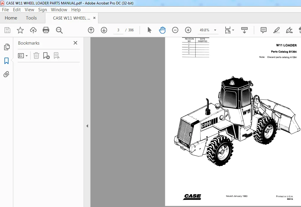
Issued January, 1983
Fan defroster
Fan heater
Fan radiator
Fenders
Filters
Air Cleaner
Cab Air
Engine Oil
Fuel
Hydraulic Oil
Hydraulic Tank
Transmission Oil
Flasher Lights
Flywheel engine
Frames
Front
Rear
Loader Lift
Fuel Filter System
Fuel Injection System
Fuel Injector Nozzles
Fuel Lines
Fuel Tank
G
Gasket engine (Service Kits)
Grille
Guards
Engine Side Panels
H
Head engine
Heater
Block engine
Cab
Hood
Horn
Hose radiator
Hose and Fitting Conversion Part Numbers
HosesSee Fuel Lines Brakes Assemblies and Hydraulic Circuits
Hydraulic Circuit
Auxiliary Steering Hydraulic Circuit
Clam bucket
Loader Arm Auxiliary
Loader Bucket
Loader Lift
Pump Flow
Return Lines
Steering
Transmission
Hydraulic Reservoir Assembly
Index numerical
Instrument Panel
Instruments See Gauges
L
Lamps
Loader
Buckets
Hydraulic Circuits
Lift Frame
M
Manifold
Exhaust
Intake
Mirrors
Motor Auxiliary Steering
Mounting
Axle
Cab
Engine
Radiator
Transmission
Mufflers
N
Nozzle cold starting fluid
Nozzle fuel injector
Numerical Index
o
Oil Cooler transmission
Oil Filter
Engine
Hydraulic
Transmission
Oil Pan engine
Oil Pump engine
p s
Pan engine oil
Panel instrument
Parking Brake
Pedal accelerator
Piston Assemblies engine
Pulleys
Alternator
Alternator and Fan Drive
Pump Drive water
Pumps
Auxiliary Steering
Engine oil
Fuel Injection
Fuel electric
Hydraulic Oil
Steering
Transmission Charging
Water engine
R
Radiator cooling
Regulator voltage
Reservoirs
Fuel
Hydraulic Oil
Return To Dig
Rims wheel
Rings engine piston
Rocker Arms engine
Rods connecting
Rods push
s
Seat Assemblies
Seat Belts
Senders
Engine Oil Pressure
Fuel Gauge
Temperature transmission
Temperature water
Shafts
Axle (See Axle Assemblies)
Drive
Engine (See Engine Components) Transmission (See Transmission Components)
Shroud radiator
Side Panels engine
Sleeve piston
Solenoid auxiliary steering
Solenoid starter
Starter engine
Starting Aid (Ether Injection)
Steering
Steps
Switches
Auxiliary Steering
Backup Alarm
Blower Fan cab
Clutch Pressure
Cold Start
Defroster cab
Dome Lamp cab
Heater cab
Key and Starter
Lamp driving
Loader Height Control
Neutral Start
Parking Brake
Return To Dig
Stop Lamp
Strobe Lamp
Turn Signal and Flasher
T
Tachometer
Tank
Fuel
Hydraulic Oil
Temperature Sending Unit
Thermostat water temperature
Timing Gear Cover engine
Torque Converter
Transmission Mounts
Transmission
Charging Pump
Control Valve
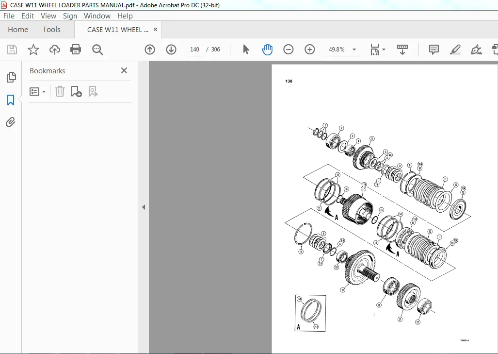
First Forward and Third Clutches
Front Housing and Idler
Front Housing Input Shaft and Pump Drive Output Shaft and Cover
Second and Reverse Clutches
Torque Converter and Flex Plates
Yoke and Brake
Trunnion rear frame
Turn Signals
V
Valve Mechanism engine
Valve Levers loader control
Valves
Brake Actuator
Breather axle
Clutch Cutout
Drain radiator
Flow Control steering
Loader Control
Steering Control
Tire valve stem
Transmission Control
Unloading
w
Water Pump
Wheel steering
Wheel tire
Windows cab
Wiper windshield
Wire-See Electrical Circuits
CASE W11 WHEEL LOADER PARTS MANUAL – PDF DOWNLOAD:
IMAGES PREVIEW OF THE MANUAL:
PLEASE NOTE:
- This is the SAME manual used by the dealers to troubleshoot any faults in your vehicle. This can be yours in 2 minutes after the payment is made.
- Contact us at [email protected] should you have any queries before your purchase or that you need any other service / repair / parts operators manual.