Case WX150 WX170 & WX200 Wheeled Excavators Operator’s Manual 6-33240 – PDF DOWNLOAD
Original price was: $89.95.$29.95Current price is: $29.95.
Case WX150 WX170 & WX200 Wheeled Excavators Operator’s Manual 6-33240 – PDF DOWNLOAD
Description
Case WX150 WX170 & WX200 Wheeled Excavators Operator’s Manual 6-33240 – PDF DOWNLOAD
DESCRIPTION:
Case WX150 WX170 & WX200 Wheeled Excavators Operator’s Manual 6-33240 – PDF DOWNLOAD
TO THE OWNER :
Your machine has been designed and built to the highest standards of quality. It conforms to all current safety regulations. See “Official documents”. However, the risk of accidents can never be completely excluded. That is why it is essential to observe elementary safety rules and precautions.
- Read this manual carefully, paying particular attention to the instructions concerning safety, operation and maintenance so as to avoid the risk of injury while operating or servicing the machine. The standard attachments and equipment available for use with this machine are intended for general earthmoving purposes, material rehandling etc.
- If the machine is to be used for handling loads, (tubing, concrete pipe sections, shoring material, etc.), make sure the machine is suitably equipped for this type of work. For this type of application, the machine must be equipped with safety valves, an overload indicator, a load handling chart corresponding to the type of machine and its attachment and a load fixing point. All legal requirements must also be strictly observed.
- Do not use this machine for any application or purpose other than those described in this manual. If the machine is to be used for work involving the use of special attachments, accessories or equipment, consult your CASE Dealer in order to make sure that any adaptations or modifications made are in keeping with the machine’s technical specifications and with prevailing safety requirements.
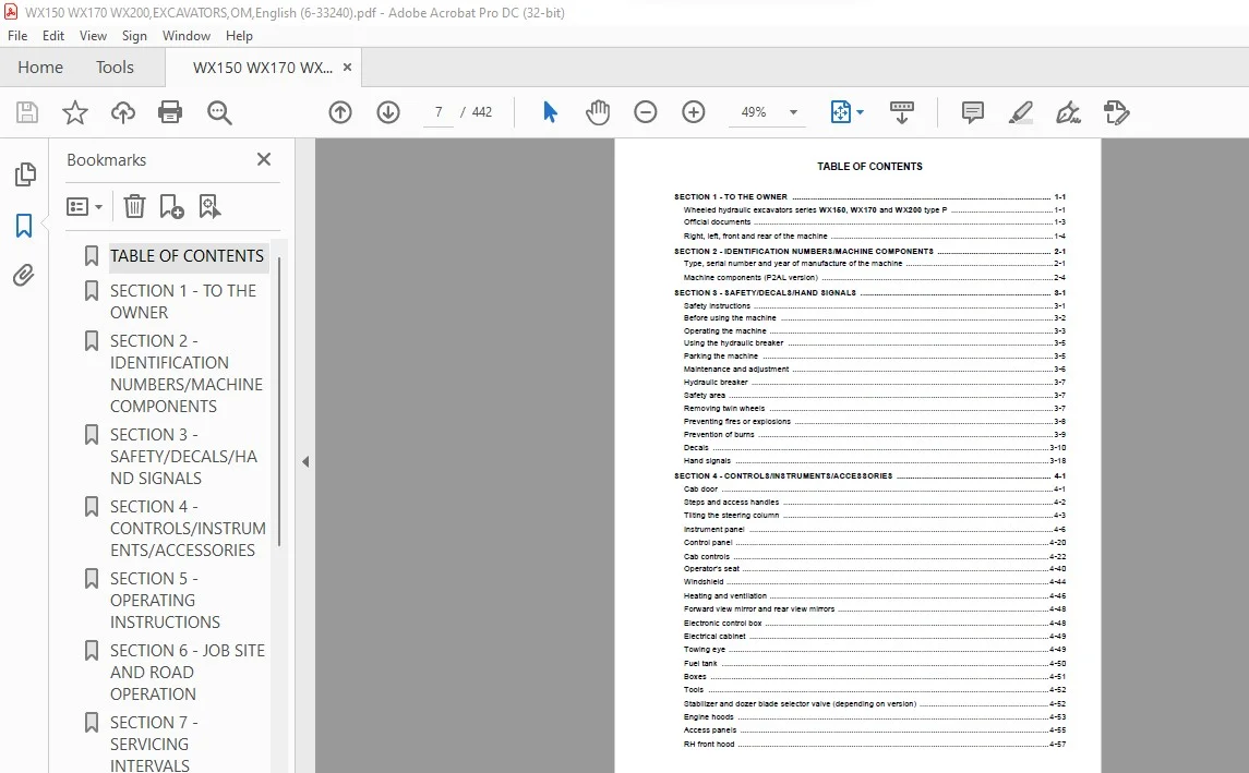
TABLE OF CONTENTS:
Case WX150 WX170 & WX200 Wheeled Excavators Operator’s Manual 6-33240 – PDF DOWNLOAD
1 – To the owner
2 – Identification numbers/Machine components
3 – Safety/Decals/Hand signals
4 – Controls/Instruments/Accessories
5 – Operating instructions
6 – Job site and road operation
7 – Servicing intervals
8 – Lubrication/Filters/Fluids
9 – Maintenance/Adjustments
10 – Electrical system
11 – Storage
12 – Specifications
13 – Alphabetical index
SECTION 1 – TO THE OWNER …………………………………………………………………………………………………… 1-1
Wheeled hydraulic excavators series WX150, WX170 and WX200 type P ……………………………………… 1-1
Official documents …………………………………………………………………………………………………………………… 1-3
Right, left, front and rear of the machine …………………………………………………………………………………….. 1-4
SECTION 2 – IDENTIFICATION NUMBERS/MACHINE COMPONENTS ………………………………………….. 2-1
Type, serial number and year of manufacture of the machine ……………………………………………………….. 2-1
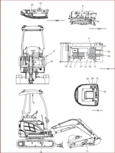
Machine components (P2AL version) ………………………………………………………………………………………… 2-4
SECTION 3 – SAFETY/DECALS/HAND SIGNALS ………………………………………………………………………… 3-1
Safety instructions …………………………………………………………………………………………………………………… 3-1
Before using the machine ………………………………………………………………………………………………………… 3-2
Operating the machine …………………………………………………………………………………………………………….. 3-3
Using the hydraulic breaker ……………………………………………………………………………………………………… 3-5
Parking the machine ……………………………………………………………………………………………………………….. 3-5
Maintenance and adjustment ……………………………………………………………………………………………………. 3-6
Hydraulic breaker ……………………………………………………………………………………………………………………. 3-7
Safety area …………………………………………………………………………………………………………………………….. 3-7
Removing twin wheels …………………………………………………………………………………………………………….. 3-7
Preventing fires or explosions …………………………………………………………………………………………………… 3-8
Prevention of burns …………………………………………………………………………………………………………………. 3-9
Decals ………………………………………………………………………………………………………………………………….3-10
Hand signals …………………………………………………………………………………………………………………………3-18
SECTION 4 – CONTROLS/INSTRUMENTS/ACCESSORIES ………………………………………………………….. 4-1
Cab door ……………………………………………………………………………………………………………………………….. 4-1
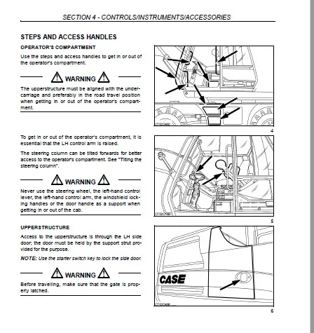
Steps and access handles ……………………………………………………………………………………………………….. 4-2
Tilting the steering column ……………………………………………………………………………………………………….. 4-3
Instrument panel …………………………………………………………………………………………………………………….. 4-6
Control panel …………………………………………………………………………………………………………………………4-20
Cab controls …………………………………………………………………………………………………………………………. 4-22
Operator’s seat ………………………………………………………………………………………………………………………4-40
Windshield …………………………………………………………………………………………………………………………….4-44
Heating and ventilation ……………………………………………………………………………………………………………4-46
Forward view mirror and rear view mirrors …………………………………………………………………………………4-48
Electronic control box ……………………………………………………………………………………………………………..4-48
Electrical cabinet ……………………………………………………………………………………………………………………4-49
Towing eye ……………………………………………………………………………………………………………………………4-49
Fuel tank ………………………………………………………………………………………………………………………………4-50
Boxes …………………………………………………………………………………………………………………………………..4-51
Tools ……………………………………………………………………………………………………………………………………4-52
Stabilizer and dozer blade selector valve (depending on version) ………………………………………………… 4-52
Engine hoods ………………………………………………………………………………………………………………………..4-53
Access panels ……………………………………………………………………………………………………………………….4-55
RH front hood ………………………………………………………………………………………………………………………..4-57
TABLE OF CONTENTS
Controls/Instruments/Accessories (continued)
Tray under the operator’s compartment …………………………………………………………………………………….4-57
Electrical socket ……………………………………………………………………………………………………………………..4-58
Stabilizer pads ……………………………………………………………………………………………………………………….4-58
Foldable stabilizers (series WX150 and WX170) ………………………………………………………………………..4-60
Reflection markers ………………………………………………………………………………………………………………….4-62
Hydraulic reservoir shut-off valve ……………………………………………………………………………………………..4-63
Battery master switch ……………………………………………………………………………………………………………..4-64
Load handling fixing point ………………………………………………………………………………………………………..4-64
Valve bank partition hood ………………………………………………………………………………………………………..4-66
Engine compartment light ………………………………………………………………………………………………………..4-66
Wheel blocks …………………………………………………………………………………………………………………………4-67
Boom locking valves ……………………………………………………………………………………………………………….4-67
Dipper locking valves ………………………………………………………………………………………………………………4-68
Bucket/clamshell selector valve ………………………………………………………………………………………………..4-69
Safety valves …………………………………………………………………………………………………………………………4-69
Fuel tank filler pump ……………………………………………………………………………………………………………….4-70
Rotary beacon ……………………………………………………………………………………………………………………….4-72
Maximum opening range and maximum force ……………………………………………………………………………4-74
SECTION 5 – OPERATING INSTRUCTIONS ………………………………………………………………………………… 5-1
Before operating the machine ……………………………………………………………………………………………………5-1
Machine operation ……………………………………………………………………………………………………………………5-2
Run-in period …………………………………………………………………………………………………………………………..5-3
Starting the engine …………………………………………………………………………………………………………………..5-4
Starting the engine in cold weather …………………………………………………………………………………………….5-8
Anti-theft protection ………………………………………………………………………………………………………………..5-10
Immobiliser code ……………………………………………………………………………………………………………………5-12
Stopping the engine ………………………………………………………………………………………………………………..5-13
Operating the machine in cold weather ……………………………………………………………………………………..5-15
Installing the fuel tank cap ……………………………………………………………………………………………………….5-16
Load handling ………………………………………………………………………………………………………………………..5-17
Maximum load handling capacity limits ……………………………………………………………………………………..5-18
Handling the hydraulic breaker …………………………………………………………………………………………………5-19
Breaking techniques with the hydraulic breaker ………………………………………………………………………….5-20
Choice of tools ……………………………………………………………………………………………………………………….5-20
Special conditions of use for the hydraulic breaker ……………………………………………………………………..5-20
Transporting the machine ………………………………………………………………………………………………………..5-21
Handling the machine ……………………………………………………………………………………………………………..5-27
Cab removal and installation ……………………………………………………………………………………………………5-29
Towing the machine ……………………………………………………………………………………………………………….5-33
Towing the machine in an emergency ……………………………………………………………………………………….5-37
TABLE OF CONTENTS
Operating instructions (continued)
Operating the machine in water ……………………………………………………………………………………………….5-37
Electric travel control ………………………………………………………………………………………………………………5-38
Dozer blade/stabilizers configuration from the operator’s compartment (P2AL version)
(with independent dozer blade/stabilizers, if equipped) …………………………………………………………… 5-40
Parking the machine ………………………………………………………………………………………………………………5-43
SECTION 6 – JOB SITE AND ROAD OPERATION ……………………………………………………………………….. 6-1
Operating instructions ……………………………………………………………………………………………………………… 6-1
Road travel …………………………………………………………………………………………………………………………….. 6-2
Attaching the CASE clamshell for road travel (type P) ………………………………………………………………… 6-15
Fastening the short clamshell for road travel
(Series WX200 type PM, special for Germany) ………………………………………………………………………6-19
Job site travel ………………………………………………………………………………………………………………………..6-21
Working instructions ……………………………………………………………………………………………………………….6-23
Load handling ………………………………………………………………………………………………………………………..6-29
SECTION 7 – SERVICING INTERVALS ……………………………………………………………………………………….. 7-1
Service instructions …………………………………………………………………………………………………………………. 7-1
Hourmeter ……………………………………………………………………………………………………………………………… 7-2
Service intervals chart ……………………………………………………………………………………………………………… 7-3
Hydraulic breaker servicing intervals ………………………………………………………………………………………….. 7-6
SECTION 8 – LUBRICATION/FILTERS/FLUIDS ……………………………………………………………………………. 8-1
Fluids and lubricants ……………………………………………………………………………………………………………….. 8-1
Environment …………………………………………………………………………………………………………………………… 8-3
Plastic and resin components …………………………………………………………………………………………………… 8-3
Fluids and lubricants capacities and specifications ………………………………………………………………………. 8-4
Grease points …………………………………………………………………………………………………………………………. 8-5
Greasing the hydraulic breaker ………………………………………………………………………………………………..8-42
Fluid levels ……………………………………………………………………………………………………………………………8-43
Engine (WX150) ……………………………………………………………………………………………………………………. 8-47
Engine (WX170) ……………………………………………………………………………………………………………………. 8-50
Engine (WX200) ……………………………………………………………………………………………………………………. 8-53
Cooling system ………………………………………………………………………………………………………………………8-56
Fuel system (WX150) …………………………………………………………………………………………………………….. 8-59
Fuel system (WX170) …………………………………………………………………………………………………………….. 8-64
Fuel system (WX200) …………………………………………………………………………………………………………….. 8-69
Releasing pressure in the hydraulic system ……………………………………………………………………………….8-74
Hydraulic system ……………………………………………………………………………………………………………………8-75
Air filter …………………………………………………………………………………………………………………………………8-83
Swing reduction gear ……………………………………………………………………………………………………………..8-89
Axles and reduction gears ……………………………………………………………………………………………………….8-91
Gearbox ……………………………………………………………………………………………………………………………….8-97
TABLE OF CONTENTS
SECTION 9 – MAINTENANCE/ADJUSTMENTS ……………………………………………………………………………. 9-1
Fuel tank filter ………………………………………………………………………………………………………………………….9-1
Front axle locking cylinders ……………………………………………………………………………………………………….9-1
Wheels and tyres ……………………………………………………………………………………………………………………..9-2
Replacing twin wheels ………………………………………………………………………………………………………………9-3
Heating unit filter …………………………………………………………………………………………………………………….9-13
Radiator and oil cooler …………………………………………………………………………………………………………….9-14
Engine alternator belt ……………………………………………………………………………………………………………..9-15
Adjusting rocker arm clearance ………………………………………………………………………………………………..9-16
Inspecting and cleaning the machine ………………………………………………………………………………………..9-16
Inspecting the turntable bearing ……………………………………………………………………………………………….9-16
Accumulators …………………………………………………………………………………………………………………………9-17
Replacing a backhoe bucket tooth tip ………………………………………………………………………………………..9-18
Teeth and tooth tip wear limits ………………………………………………………………………………………………….9-19
Replacing a backhoe bucket side cutter …………………………………………………………………………………….9-19
Replacing a backhoe bucket ……………………………………………………………………………………………………9-20
Replacing a clamshell tooth ……………………………………………………………………………………………………..9-27
Replacing a clamshell and its universal coupling ………………………………………………………………………..9-27
Replacing a backhoe bucket with a clamshell (or vice-versa) ……………………………………………………….9-30
Replacing an ejector bucket …………………………………………………………………………………………………….9-33
Adjusting the hydraulically locking adjustable boom ……………………………………………………………………9-37
Replacing a tool on a hydraulic breaker …………………………………………………………………………………….9-39
Replacing a tool bushing on a hydraulic breaker …………………………………………………………………………9-41
Replacing a hydraulic breaker ………………………………………………………………………………………………….9-43
Wear limits on a hydraulic breaker ……………………………………………………………………………………………9-44
Sleeves for threaded pins ………………………………………………………………………………………………………..9-45
Replacing a hose ……………………………………………………………………………………………………………………9-45
Replacing standard pins with “Expander” pins ……………………………………………………………………………9-46
Checking for cylinder leakage ………………………………………………………………………………………………….9-47
Shimming of attachments ………………………………………………………………………………………………………..9-48
Air conditioning ………………………………………………………………………………………………………………………9-50
Engine troubleshooting ……………………………………………………………………………………………………………9-53
SECTION 10 – ELECTRICAL SYSTEM ………………………………………………………………………………………. 10-1
Fuses and relays ……………………………………………………………………………………………………………………10-1
Batteries ……………………………………………………………………………………………………………………………….10-4
Booster batteries ……………………………………………………………………………………………………………………10-7
Alternator ………………………………………………………………………………………………………………………………10-8
Starter motor ………………………………………………………………………………………………………………………….10-8
Electronic control box ……………………………………………………………………………………………………………..10-9
Temperature sender ……………………………………………………………………………………………………………..10-10
Bulbs …………………………………………………………………………………………………………………………………..10-11
Replacing a bulb …………………………………………………………………………………………………………………..10-11
TABLE OF CONTENTS
SECTION 11 – STORAGE …………………………………………………………………………………………………………. 11-1
Storing the machine ……………………………………………………………………………………………………………….11-1
Storing the hydraulic breaker …………………………………………………………………………………………………..11-2
SECTION 12 – SPECIFICATIONS ……………………………………………………………………………………………… 12-1
Engine ………………………………………………………………………………………………………………………………….12-1
Hydraulic system ……………………………………………………………………………………………………………………12-2
Electrical system ……………………………………………………………………………………………………………………12-2
Upperstructure ………………………………………………………………………………………………………………………12-3
Cab ………………………………………………………………………………………………………………………………………12-3
Operation ……………………………………………………………………………………………………………………………..12-3
Undercarriage (depending on version) ………………………………………………………………………………………12-4
Tyres ……………………………………………………………………………………………………………………………………12-4
Brakes ………………………………………………………………………………………………………………………………….12-4
Safety devices ……………………………………………………………………………………………………………………….12-4
Indicators ………………………………………………………………………………………………………………………………12-4
Travel …………………………………………………………………………………………………………………………………..12-5
Attachments …………………………………………………………………………………………………………………………. 12-5
Noise level …………………………………………………………………………………………………………………………….12-5
Vibration level inside the cab …………………………………………………………………………………………………..12-5
Weights ……………………………………………………………………………………………………………………………….. 12-6
Buckets ……………………………………………………………………………………………………………………………… 12-10
Clamshells …………………………………………………………………………………………………………………………..12-13
Hydraulic breaker …………………………………………………………………………………………………………………12-16
Machine overall dimensions ………………………………………………………………………………………………….. 12-24
Working range ……………………………………………………………………………………………………………………..12-34
Transportation overall dimensions ………………………………………………………………………………………….12-44
Overall road travel dimensions ……………………………………………………………………………………………….12-50
Attachment configurations ……………………………………………………………………………………………………..12-51
Material density/handling table (backhoe attachment) ……………………………………………………………….12-53
Material density/handling table (clamshell attachment) ………………………………………………………………12-58
Density of various soils and materials ……………………………………………………………………………………..12-61
SECTION 13 – ALPHABETICAL INDEX …………………………………………………………………………………….. 13-1
IMAGES PREVIEW OF THE MANUAL:
CASE WX150 WX170 & WX200 WHEELED EXCAVATORS OPERATOR’S MANUAL 6-33240 – PDF DOWNLOAD:
PLEASE NOTE:
- This is the SAME exact manual used by your dealers to fix your vehicle.
- The same can be yours in the next 2-3 mins as you will be directed to the download page immediately after paying for the manual.
- Any queries / doubts regarding your purchase, please feel free to contact [email protected]
S.V