Case WX210 Industrial WX240 Industrial wheeled Excavators Stage IIIA Operator’s Manual 84285859 – PDF DOWNLOAD
Original price was: $89.95.$28.95Current price is: $28.95.
Case WX210 Industrial WX240 Industrial wheeled Excavators Stage IIIA Operator’s Manual 84285859 – PDF DOWNLOAD
Description
Case WX210 Industrial WX240 Industrial wheeled Excavators Stage IIIA Operator’s Manual 84285859 – PDF DOWNLOAD
DESCRIPTION:
Case WX210 Industrial WX240 Industrial wheeled Excavators Stage IIIA Operator’s Manual 84285859 – PDF DOWNLOAD
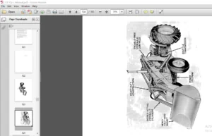
- The crawler mini excavators are hydraulic machines. They consist of two main parts: the upper frame and the lower frame. These components are coupled by means of a slewing bearing which enables the upper frame to slew with respect to the lower frame.
- The boom, tanks, radiators, counterweight, diesel engine and all hydraulic components for the operation of the excavator are fastened to the upper frame. The lower frame is equipped with crawlers which can be made of rubber or metal and with a blade for levelling operations.
- The machine has been built in accordance with state-of-the-art standards and the recognized safety rules. The machine must be used in accordance with its designated use, by observing the safety and precautionary rules and by strictly following the operating instructions.
- Any functional disorders, especially those affecting the safety of the machine, should therefore be rectified immediately. The Excavator is intended to be used in digging and loading operation (with bucket), ground levelling (with blade) and use of hydraulic hammer to break concrete or other solid material.
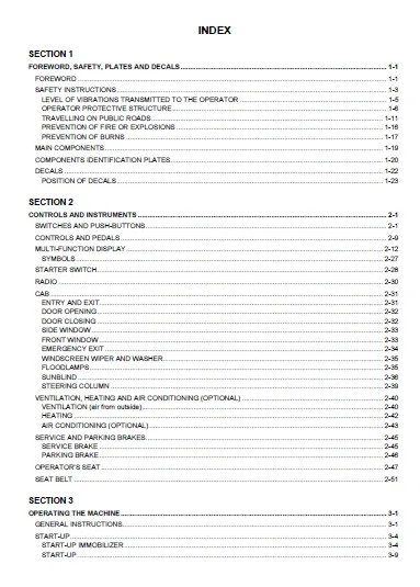
TABLE OF CONTENTS:
Case WX210 Industrial WX240 Industrial wheeled Excavators Stage IIIA Operator’s Manual 84285859 – PDF DOWNLOAD
1 – FOREWORD, SAFETY, PLATES AND DECALS
2 – CONTROLS AND INSTRUMENTS
3 – OPERATING THE MACHINE
4 – SUPPLIES AND MAINTENANCE CHART
5 – STORAGE
6 – ACCESSORIES
7 – DATA AND TECHNICAL SPECIFICATIONS
8 – ALPHABETICAL INDEX
ATTACHMENT 1 – “EC” DECLARATION OF CONFORMITY
FOREWORD, SAFETY, PLATES AND DECALS…………………………………………………………………………………………….. 1-1
FOREWORD ……………………………………………………………………………………………………………………………………………. 1-1
SAFETY INSTRUCTIONS………………………………………………………………………………………………………………………….. 1-3
LEVEL OF VIBRATIONS TRANSMITTED TO THE OPERATOR …………………………………………………………………. 1-5
OPERATOR PROTECTIVE STRUCTURE………………………………………………………………………………………………… 1-6
TRAVELLING ON PUBLIC ROADS………………………………………………………………………………………………………… 1-11
PREVENTION OF FIRE OR EXPLOSIONS …………………………………………………………………………………………….. 1-16
PREVENTION OF BURNS ……………………………………………………………………………………………………………………. 1-17
MAIN COMPONENTS……………………………………………………………………………………………………………………………… 1-19
COMPONENTS IDENTIFICATION PLATES……………………………………………………………………………………………….. 1-20
DECALS ………………………………………………………………………………………………………………………………………………… 1-22
POSITION OF DECALS………………………………………………………………………………………………………………………… 1-23
SECTION 2
CONTROLS AND INSTRUMENTS ………………………………………………………………………………………………………………… 2-1
SWITCHES AND PUSH-BUTTONS…………………………………………………………………………………………………………….. 2-1
CONTROLS AND PEDALS………………………………………………………………………………………………………………………… 2-9
MULTI-FUNCTION DISPLAY……………………………………………………………………………………………………………………. 2-12
SYMBOLS…………………………………………………………………………………………………………………………………………… 2-27
STARTER SWITCH…………………………………………………………………………………………………………………………………. 2-28
RADIO …………………………………………………………………………………………………………………………………………………… 2-30
CAB ………………………………………………………………………………………………………………………………………………………. 2-31
ENTRY AND EXIT………………………………………………………………………………………………………………………………… 2-31
DOOR OPENING…………………………………………………………………………………………………………………………………. 2-32
DOOR CLOSING …………………………………………………………………………………………………………………………………. 2-32
SIDE WINDOW……………………………………………………………………………………………………………………………………. 2-33
FRONT WINDOW ………………………………………………………………………………………………………………………………… 2-33
EMERGENCY EXIT ……………………………………………………………………………………………………………………………… 2-34
WINDSCREEN WIPER AND WASHER…………………………………………………………………………………………………… 2-35
FLOODLAMPS…………………………………………………………………………………………………………………………………….. 2-35
SUNBLIND………………………………………………………………………………………………………………………………………….. 2-36
STEERING COLUMN …………………………………………………………………………………………………………………………… 2-39
VENTILATION, HEATING AND AIR CONDITIONING (OPTIONAL) ………………………………………………………………. 2-40
VENTILATION (air from outside)…………………………………………………………………………………………………………….. 2-40
HEATING ……………………………………………………………………………………………………………………………………………. 2-42
AIR CONDITIONING (OPTIONAL) …………………………………………………………………………………………………………. 2-43
SERVICE AND PARKING BRAKES…………………………………………………………………………………………………………… 2-45
SERVICE BRAKE ………………………………………………………………………………………………………………………………… 2-45
PARKING BRAKE………………………………………………………………………………………………………………………………… 2-46
OPERATOR’S SEAT……………………………………………………………………………………………………………………………….. 2-47
SEAT BELT ……………………………………………………………………………………………………………………………………………. 2-51
SECTION 3
OPERATING THE MACHINE………………………………………………………………………………………………………………………… 3-1
GENERAL INSTRUCTIONS……………………………………………………………………………………………………………………….. 3-1
START-UP……………………………………………………………………………………………………………………………………………….. 3-4
START-UP IMMOBILIZER………………………………………………………………………………………………………………………. 3-4
START-UP ……………………………………………………………………………………………………………………………………………. 3-9
INDEX
ENGINE SHUT OFF……………………………………………………………………………………………………………………………… 3-12
CAB AT VARIABLE HEIGHT…………………………………………………………………………………………………………………….. 3-13
TRAVEL…………………………………………………………………………………………………………………………………………………. 3-16
BEFORE STARTING THE TRAVEL ……………………………………………………………………………………………………….. 3-16
BASIC POSITION ………………………………………………………………………………………………………………………………… 3-16
TRAVEL ……………………………………………………………………………………………………………………………………………… 3-18
GEARBOX – GEAR CHANGE………………………………………………………………………………………………………………… 3-21
WORKING OPERATION………………………………………………………………………………………………………………………….. 3-25
SAFETY INSTRUCTIONS …………………………………………………………………………………………………………………….. 3-25
BEFORE BEGINNING THE WORK………………………………………………………………………………………………………… 3-26
HOLDING AND RELEASING THE UPPER STRUCTURE SLEWING …………………………………………………………. 3-31
STABILIZATION OF THE MACHINE………………………………………………………………………………………………………. 3-43
OPERATING THE MACHINE WITH COLD WEATHER………………………………………………………………………………… 3-46
OPERATING THE MACHINE WITH HOT WEATHER………………………………………………………………………………….. 3-49
MACHINE RECOVERY AND TOWING………………………………………………………………………………………………………. 3-50
SECURE THE MACHINE………………………………………………………………………………………………………………………. 3-51
WORKING ATTACHMENT……………………………………………………………………………………………………………………….. 3-56
CLAMSHELL BUCKET OPERATION ……………………………………………………………………………………………………… 3-57
SECTION 4
SUPPLIES AND MAINTENANCE CHART ……………………………………………………………………………………………………… 4-1
SUPPLIES AND MAINTENANCE CHART……………………………………………………………………………………………………. 4-1
SAFETY INSTRUCTIONS………………………………………………………………………………………………………………………….. 4-5
WORKING HOURS / INTERVALS ………………………………………………………………………………………………………………. 4-6
MAINTENANCE INTERVALS CHART …………………………………………………………………………………………………………. 4-7
CHECKS BEFORE START-UP AND BEFORE EACH WORKING SHIFT (10 HOURS) ……………………………………. 4-10
WEEKLY SERVICE (50 HOURS)………………………………………………………………………………………………………………. 4-22
MONTHLY SERVICE (250 HOURS)………………………………………………………………………………………………………….. 4-32
SERVICE EVERY 12 MONTHS (500 HOURS)……………………………………………………………………………………………. 4-40
SERVICE AFTER 1000 HOURS ……………………………………………………………………………………………………………….. 4-46
SERVICE AFTER 3000 HOURS ……………………………………………………………………………………………………………….. 4-59
SERVICE WHEN NECESSARY………………………………………………………………………………………………………………… 4-66
SECTION 5
STORAGE ………………………………………………………………………………………………………………………………………………….. 5-1
SECTION 6
ACCESSORIES…………………………………………………………………………………………………………………………………………… 6-1
CLAMSHELL ……………………………………………………………………………………………………………………………………………. 6-1
CRANING HOOK………………………………………………………………………………………………………………………………………. 6-6
OVERLOAD WARNING SYSTEM……………………………………………………………………………………………………………….. 6-7
“MOZELT” MAGNET …………………………………………………………………………………………………………………………………. 6-9
BREAK PROTECTION VALVES……………………………………………………………………………………………………………….. 6-16
REAR FLOODLAMPS ……………………………………………………………………………………………………………………………… 6-17
ROTARY LIGHT ……………………………………………………………………………………………………………………………………… 6-18
FUEL TRANSFER PUMP…………………………………………………………………………………………………………………………. 6-19
CAB PROTECTIONS ………………………………………………………………………………………………………………………………. 6-20
CENTRALIZED LUBRICATION…………………………………………………………………………………………………………………. 6-21
MAINTENANCE …………………………………………………………………………………………………………………………………… 6-22
INDEX
SECTION 7
DATA AND TECHNICAL SPECIFICATIONS ………………………………………………………………………………………………….. 7-1
DIMENSIONS – OPERATING WEIGHTS……………………………………………………………………………………………………… 7-1
WX 210 Industrial MODELS…………………………………………………………………………………………………………………….. 7-1
WX 240 Industrial MODELS…………………………………………………………………………………………………………………….. 7-2
DIGGING PERFORMANCE ……………………………………………………………………………………………………………………….. 7-3
WX 210 Industrial MODELS…………………………………………………………………………………………………………………….. 7-3
WX 240 Industrial MODELS…………………………………………………………………………………………………………………….. 7-4
LIFTING CAPACITIES……………………………………………………………………………………………………………………………….. 7-5
WX 210 Industrial MODELS…………………………………………………………………………………………………………………….. 7-5
WX 240 Industrial MODELS…………………………………………………………………………………………………………………….. 7-6
HYDRAULIC SYSTEM ………………………………………………………………………………………………………………………………. 7-7
PUMPS…………………………………………………………………………………………………………………………………………………. 7-7
CYLINDERS (ø for stroke) ………………………………………………………………………………………………………………………. 7-7
SLEWING ………………………………………………………………………………………………………………………………………………… 7-7
TRAVEL…………………………………………………………………………………………………………………………………………………… 7-7
TYRES …………………………………………………………………………………………………………………………………………………. 7-8
BRAKES ………………………………………………………………………………………………………………………………………………….. 7-8
STEERING ………………………………………………………………………………………………………………………………………………. 7-8
POWER STEERING ………………………………………………………………………………………………………………………………. 7-8
ELECTRICAL SYSTEM……………………………………………………………………………………………………………………………… 7-9
TIGHTENING TORQUES…………………………………………………………………………………………………………………………… 7-9
FUEL SYSTEM…………………………………………………………………………………………………………………………………………. 7-9
ENGINE…………………………………………………………………………………………………………………………………………………. 7-10
SECTION 8
ALPHABETICAL INDEX ………………………………………………………………………………………………………………………………. 1-1
IMAGES PREVIEW OF THE MANUAL:
CASE WX210 INDUSTRIAL WX240 INDUSTRIAL WHEELED EXCAVATORS STAGE IIIA OPERATOR’S MANUAL 84285859 – PDF DOWNLOAD:
PLEASE NOTE:
- This is the SAME manual used by the dealers to troubleshoot any faults in your vehicle. This can be yours in 2 minutes after the payment is made.
- Contact us at [email protected] should you have any queries before your purchase or that you need any other service / repair / parts operators manual.
S.V