Cat 3000 4000 Hydra-Trac Self Contained Hydraulic Track Drill Service Manual – PDF DOWNLOAD
Original price was: $98.95.$38.95Current price is: $38.95.
Cat 3000 4000 Hydra-Trac Self Contained Hydraulic Track Drill Service Manual – PDF DOWNLOAD
Description
Cat 3000 4000 Hydra-Trac Self Contained Hydraulic Track Drill Service Manual – PDF DOWNLOAD
CAT 3000 4000 HYDRA-TRAC SELF CONTAINED HYDRAULIC TRACK DRILL SERVICE MANUAL – PDF DOWNLOAD:
IMAGES PREVIEW OF THE MANUAL:


DESCRIPTION:
Cat 3000 4000 Hydra-Trac Self Contained Hydraulic Track Drill Service Manual – PDF DOWNLOAD
Overview of Potential Hazards:
- The Track Drill is а heavy moving machine with а boom сараЫе of extending its reach vertically and horizontally. Like all moving objects and reach extending devices, there are potentlal hazards associated with its use.
- These hazards will bе minimized if the machine is properly inspected and maintained. The operators should read this manual and have Ьееп trained to use the machine in ап appropriate and safe manner. Should апу questions arise concerning the maintenance or operation of the machine .
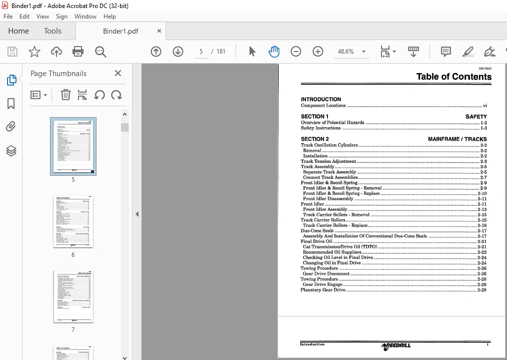
TABLE OF CONTENTS:
Cat 3000 4000 Hydra-Trac Self Contained Hydraulic Track Drill Service Manual – PDF DOWNLOAD
INTRODUCTION
Component Locations vi
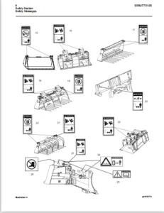
SECTION 1 SAFETY
Overview of Potential Hazards 1-2
Safety Instructions 1-3
SECTION 2 MAINFRAME / TRACKS
Track Oscillation Cylinders 2-2
Removal 2-2
Installation 2-2
Track Tension Adjustment 2-3
Track AssemЬly 2-5
Separate Track AssemЬly 2-5
Connect Track AssemЫies 2-7
Front Idler & Recoil Spring 2-9
Front Idler & Recoil Spring – Removal 2-9
Front ldler & Recoil Spring – Replace 2-10
Front Idler DisassemЬly 2-11
Front Idler 2-11
Front Idler AssemЬly 2-13
Track Carrier Rollers – Removal 2-15
Track Carrier Rollers 2-15
Track Carrier Rollers – Replace 2-16
Duo-Cone Seals 2-17
AssemЬly And Installation Of Conventional Duo-Cone Seals 2-17
Final Drive Oil 2-21
Cat Transmission/Drive Oil (TDTO) 2-21
Recommended Oil Suppliers 2-22
Checking Oil Level in Final Drive 2-24
Changing Oil in Final Drive 2-24
Towing Procedure 2-26
Gear Drive Disconnect 2-26
Towing Procedure 2-28
Gear Drive Engage 2-28
Planetary Gear Drive , 2-29
Introduction 41I-EEDRILL i
BI615942
ТаЫе of Contents
SECTION З POWER TRAIN
Main Hydraulic Pump 3-2
Removal of Hydraulic Pump 3-2
Fuel Tank 3-3
Coolers – 3-4
Service of Coolers 3-4
Removal of Coolers 3-5
Fan Guard and Motor 3-6
Fan Guard and Motor – Removal 3-6
Changing Hydraulic Oil 3-7
SECTION 4 CONTROL VALVES
Control Editor 4-2
The Function of the Control Editor 4-2
TrouЫeshooting 4-3
Electrical Schematic-Tram Controller 4-4
Electrical Schematic – Drill Controller 4-7
Hydraulic Schematic 4-9
Component Locations 4-11
Analog Input & Digital Output Modules 4-14
Digital Output Modules 4-15
Module and Controller Connectors 4-16
Tram Set-up Procedure 4-17
Parker Valves – Torque Specifications 4-18
Parker Valves – Maintenance • 4-22
SECTION 5 AIR SYSTEM
Oil Separator Tank 5-2
Preventive Maintenance/ТrouЫe Shooting 5-2
Compressor Oil Separator Agglomerator Element: 5-2
Preventive Maintenance 5-2
Air System Components 5-4
SECTION 6 ВООМ & FEED COMPONENTS
Drill / Feed Valve 6-2
Boom Piping 6-3
Feed Piping 6-4
Boom Lift Cylinder 6-6
Boom Lift Cylinder – Removal 6-6
Boom Lift Cylinder – Replace ‘ 6-7
Boom Swing Cylinder 6-8
Boom Swing Cylinder – Removal 6-8
Boom Swing Cylinder – Replace 6-8
i i 1D-EEDR/LL Introduction
BI615942
ТаЫе of Contents
SECTI0N 6 (C0NTINUED) ВООМ & FEED C0MPONENTS
Drill Positioner Dump Cylinder 6-10
Drill Positioner Dump Cylinder – Removal 6-10
Drill Positioner Dump Cylinder – Replace 6-11
3000 Boom Shim/Wear Pad Replacement 6-12
Inspection 6-13
Feed and Inner Boom Tube – Removal 6-14
Boom Tube, W ear Pad and Shims Installation 6-18
Feed Installation 6-19
4000 Boom Shim/Wear Pad Replacement 6-20
Inspection 6-21
Feed and Inner Boom Tube – Removal 6-22
Boom Tube, Wear Pad and Shims Installation 6-25
Feed Installation 6-26
Feed Chain Adjustment 6-28
Feed Swing Cylinder 6-30
Feed Swing Cylinder – Removal 6-30
Feed Swing Cylinder – Replace 6-31
Feed Extension Cylinder 6-32
Feed Extension Cylinder – Removal 6-32
Feed Extension Cylinder – Replace 6-33
Drill Replacement : 6-34
Drill – Removal 6-34
Drill – Replace 6-34
SECTI0N 7 PRESSURE SEПINGS & ADJUSTMENTS
Brake Valve Adjustments 7-2
Drill and Engine Hourmeter 7-4
Using the Editor Control Вох 7-5
Main Pump Adjustments 7-6
Roatation Pump Adjustments 7-9
SECTI0N 8 HYDRAULIC DRILL
Separate Insert for this Section
lntroduction 1§EEDRILL i i i
BI615942
ТаЫе of Contents
SECTION 9 OPTIONAL EQUIPMENT
Dust Collector AssemЬly 9-2
Operating Instructions 9-3
Function of Dust Collector 9-4
Detailed Function of Components 9-4
Initial Start-up and Tuning 9-5
Operational VariaЫes 9-6
Fine Tuning 9-7
Manometer Setup Instructions : 9-8
Timer Installation 9-10
Control Circuit 9-11
Fan Removal and Installation 9-12
TrouЫeshooting Hints , 9-13
Flame Start Control Unit 9-15
Function 9-15
Pre-glowing Times (24V) : 9-16
Post-glowing Times (24V) 9-16
Glow Stop ; 9-16
Flame Start Control Unit-TrouЫeshooting 9-17
PLEASE NOTE:
- This is the same manual used by the DEALERSHIPS to SERVICE your vehicle.
- The manual can be all yours – Once payment is complete, you will be taken to the download page from where you can download the manual. All in 2-5 minutes time!!
- Need any other service / repair / parts manual, please feel free to contact us at heydownloadss @gmail.com . We may surprise you with a nice offer
S.V