Cat 3560 Hydraulic Excavator Parts Book Manual SN 23255 – PDF DOWNLOAD
$29.95
Cat 3560 Hydraulic Excavator Parts Book Manual SN 23255 – PDF DOWNLOAD
Description
Cat 3560 Hydraulic Excavator Parts Book Manual SN 23255 – PDF DOWNLOAD
FILE DETAILS:
Cat 3560 Hydraulic Excavator Parts Book Manual SN 23255 – PDF DOWNLOAD
Language : English
Pages : 443
Downloadable : Yes
File Type : PDF
IMAGES PREVIEW OF THE MANUAL:
DESCRIPTION:
Cat 3560 Hydraulic Excavator Parts Book Manual SN 23255 – PDF DOWNLOAD
DEFINITION AND SCOPE:
- This manual describes the DC2000 Digital Adjustable Speed Drive. The DC2000 drive is a
microprocessor based power converter that provides a controlled de output for customer
application. - This manual is intended to assist applications and maintenance personnel in understanding the
equipment hardware and software.
The manual is organized as follows:
Briefly defines the DC2000 drive, with an overview of the hardware and software design.
Provides guidelines for handling and storing the DC2000 drive upon receipt.
Contains environmental, mounting, and electrical guidelines for installing the DC2000 drive, includ ing pre-startup checks.
Describes the DC2000 drive software and hardware structure, including overall operation.
Describes the function and operation of boards within the drive, including descriptions of the ad
justable hardware included on each board.
Lists and defines I/0 connector points, stabs, and LEDs for the DC2000 drive.
Lists and defines the fuses and signal testpoints available in the drive and on some boards.
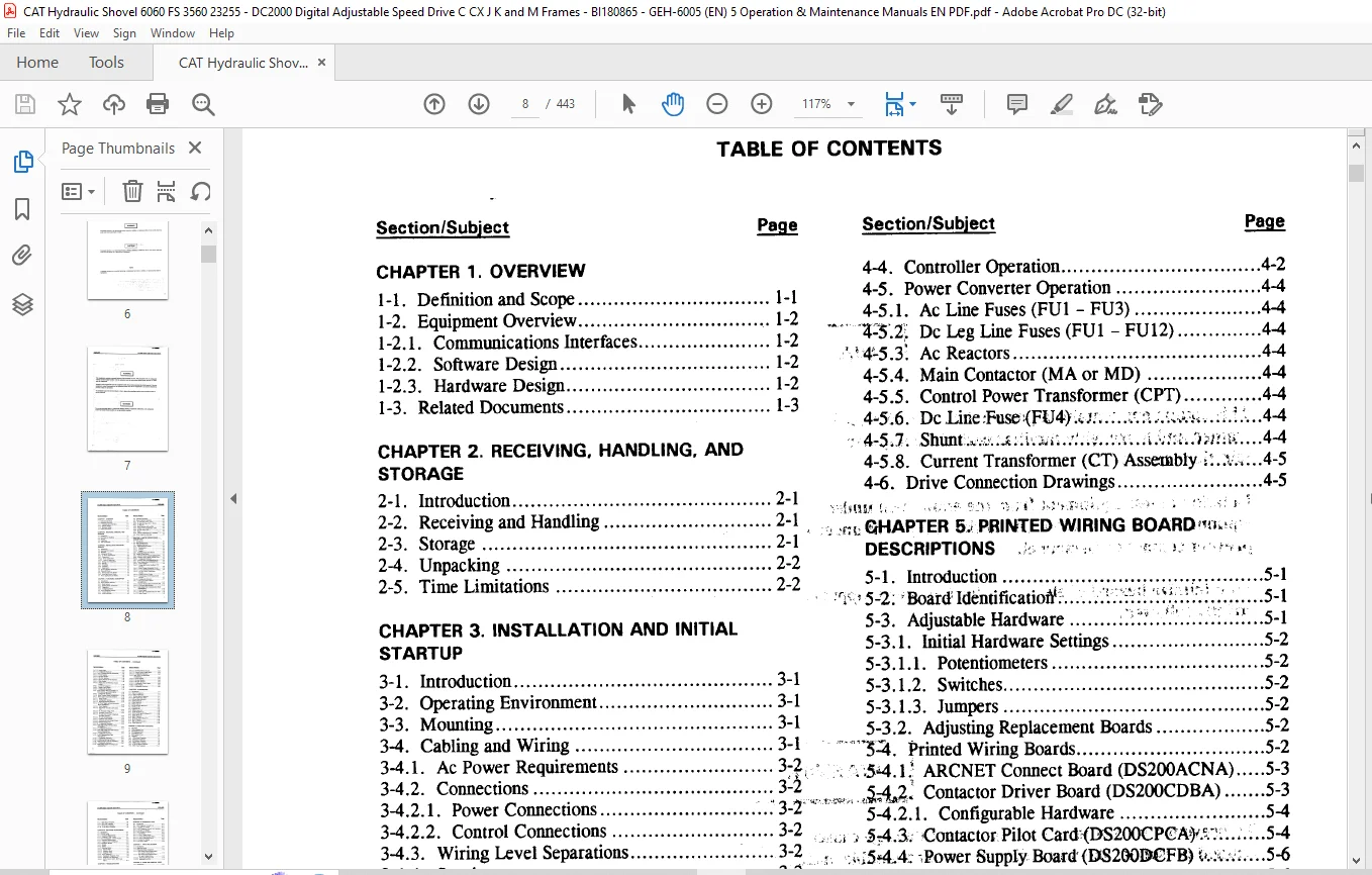
TABLE OF CONTENTS:
Cat 3560 Hydraulic Excavator Parts Book Manual SN 23255 – PDF DOWNLOAD
CHAPTER 1 OVERVIEW
1-1 Definition and Scope 1-1
1-2 Equipment Overview 1-2
1-2 1 Communications Interfaces 1-2
1-2 2 Software Design 1-2
1-2 3 Hardware Design 1-2
1-3 Related Documents 1-3
CHAPTER 2 RECEIVING, HANDLING AND
STORAGE
2-1 Introduction 2-1
2-2 Receiving and Handling 2-1
2-3 Storage 2-1
2-4 Unpacking 2-2
2-5 Time Limitations 2-2
CHAPTER 3 INSTALLATION AND INITIAL
STARTUP
3-1 Introduction 3-1
3-2 Operating Environment 3-1
3-3 Mounting 3-1
3-4 Cablingand Wiring 3-1
3-4 1 Ac PowerRequirements 3 2,
3-4 2 Connections 3-2
3-4 2 1 Power Connections 3-2
3-4 2 2 Control Connections 3-2
3-4 3 Wiring Level Separations 3-2
3-4 4 Spacing 3-3
3-4 5 Grounding 3-3
3-4 6 Commons 3-3
3-4 7 Suppression 3-3
3-5 Service and Parts Instruction 3-3
3-6 Power-off Check 3-3
3-6 1 Wiring and Circuit Checks 3-4
3-6 2 Motor and Device Checks 3-4
3-7 Power Application and Startup 3-4
CHAPTER 4 FUNCTIONAL DESCRIPTION
4-1 Introduction 4-1
4-2 Drive Software Structure 4-1
4-2 1 Block System 4-1
4-2 2 Building Block Architecture 4-1
4-2 3 Diagnostics 4-1
4-2 4 Configuring Blocks 4-2
4-3 Drive Hardware Structure 4-2
4-3 1 Control Section 4-2
4-3 2 Power Converter 4-2
Section/Subject Page
4-4 Controller Operation 4-2
4-5 Power ConverterOperation 4-4
4-5 1 Ac Line Fuses (FU1 – FU3) 4-4
VS % Dc Leg Line Fuses (FU1 -FU12) A-4
‘4-5 3* Ac Reactors 4-4
4-5 4 Main Contactor (MA or MD) 4-4
4-5 5 Control Power Transformer (CPT) 4-4
, 4-5 6 DcIJne;Fuse<FU4) 4-4
4-5 7 Shunt 4-4
4-5 8 Current Transformer (CT) Assembly 4-5
4-6 Drive Connection Drawings 4-5
tSHAPTER 5 PRINTED WIRING BOARD vu Y
DESCRIPTIONS
5-1 Introduction _ 5-1
‘ 5-2 BoardIdentification 5-1
5-3 Adjustable Hardware 2 l 5-1
5-3 1 Initial Hardware Settings 5-2
5-3 1 1 Potentiometers 5-2
5-3 1 2 Switches 5-2
5-3 1 3 Jumpers 5-2
5-3 2 Adjusting Replacement Boards 5-2
IPl Printed WiringBoards 5-2
54 1; ARCNET Connect Board (DS200ACNA) 5-3
&$£ Contactor Driver Board (DS200CDBA) 5-3
5-4 2 1 Configurable Hardware 5-4
i 5 4 3 Contactor Pilot Card>(DS200CPCA 5-4
^15*4 4; PowerSupply Board(DS28GMJFB) 5-6
5-4 4 1 PowerSupplies 5-6
5-4 4 2 Voltage and Current Feedback VCO
Circuits 5-6
5-4 4 3 Motor Voltage Attenuation Circuit 5-6
5-4 4 4 Ac Line Magnitude and Zero Crossing 5-6
5-4 4 5 Ac Line Current Transformer
Interface 5-7
5-4 4 6 Contactor Drive Circuits 5-7
5-4 4 7 Field/Armature SCR Firing Control
Circuits 5-7
5-4 4 8 Configurable Hardware 5-7
5-4 5 LAN Current Source Board
(531X207LCS) 5-11
5-4 6 LAN I/O Terminal Board (531X307LTB) 5-11
5-4 6 1 LTB Board Specifications 5-11
5-4 7 Multi-bridge Hub Communications Board
(DS200MBHA) 5-13
5-4 7 1 Power Supply 5-13
5-4 7 2 Fiber-optic Transmitter/Receiver Pairs 5-13
5-4 7 3 Mode Control 5-13
BI180865
GEH^SOOS DC2000 Digital Adjustable Speed Drive
TABLE OF CONTENTS – Continued
Section/Subject Page
5-4 7 4 System Logic 5-13
5-4 7 5 Configurable Hardware 5-13
5-4 8 Drive Terminal Board(531X305NTB) 5-14
5-4 8 1 Power Supplies 5-14
5-4 8 2 Encoder Interface 5-14
5-4 8 3 RS-232C Interface 5-14
5-4 8 4 Special Purpose RS-422 Interface 5-14
5-4 8 5 Relay Outputs 5-14
5-4 8 6 Analog Tach and Reference Coarse
Scaling „ 5-14
5-4 8 7 Low-level Analog I/O 5-14
5-4 8 8 Digital Control Inputs 5-14
5-4 8 9 Configurable Hardware 5-14
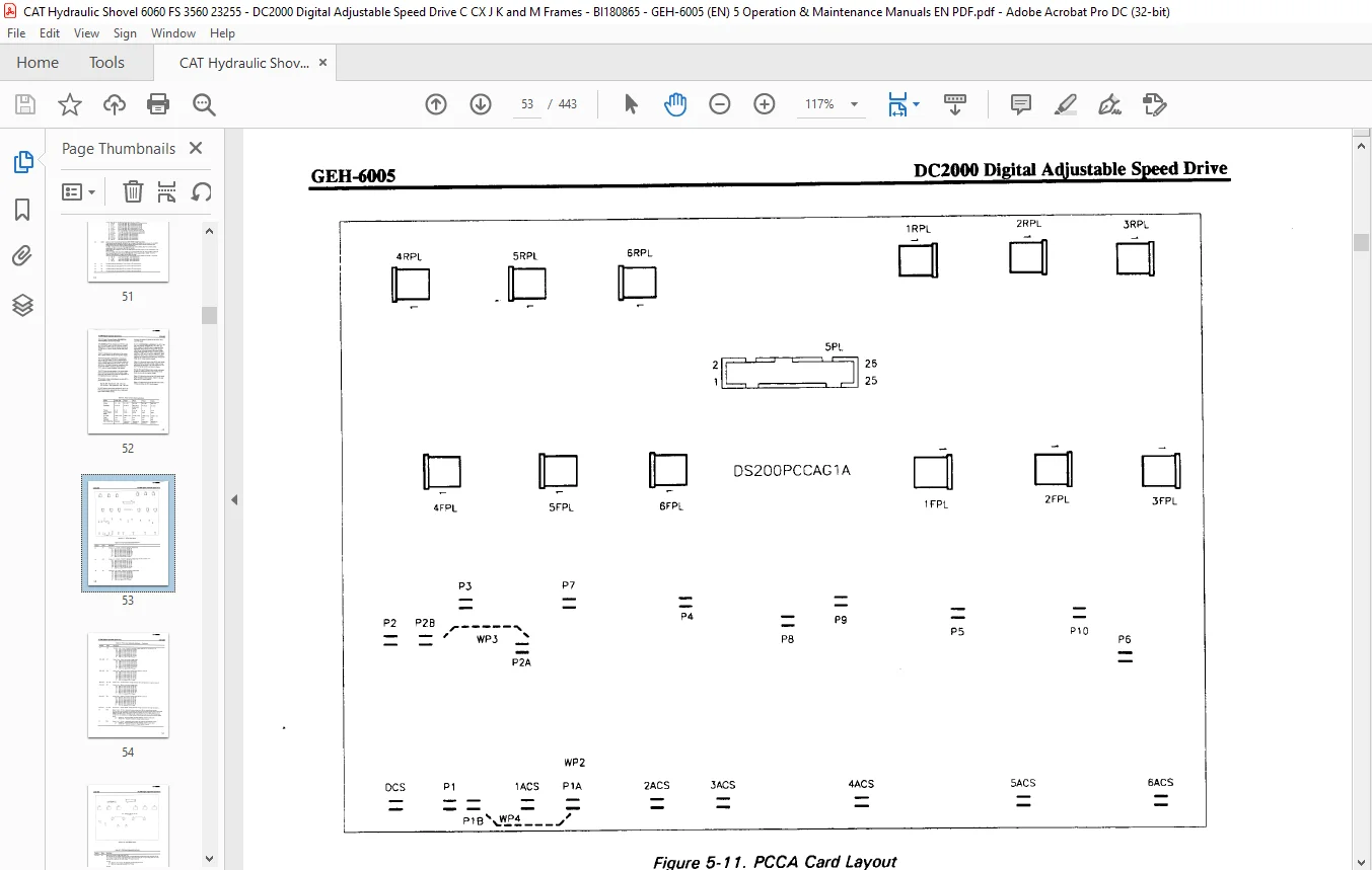
5-4 9 Power ConnectBoards (DS200PCCA,
531X122PCN, and 531X121PCR) 5-19
5-4 9 1 Configurable Hardware 5-19
5-4 10 Relay Terminal Board (DS200RTBA) 5-24
5-4 11 Drive Control Card (DS215SDCC) 5-26
5-4 11 1 Reset Circuits 5-26
5-4 11 2 Configurable Hardware 5-26
5-4 11 3 Replacing/Inserting Software 5-26
5-4 12 Dc Power Supply and Instrumentation
Board (DS200SDCI) 5-29
5-4 12 1 Power Supplies 5-29
5-4 12 2 Field Power Circuitryand Current
VCO 5-29
5-4 12 3 Dc Armature Voltage VCO 5-29
5-4 12 4 Armature Current VCO 5-30
5-4 12 5 Ac Line ZeroCrossing, Magnitude,
and Phase Sequence , 5-30
5r4il2 6 Ac Line Instrumentation 5-30
5-4 12 7 Contactor Drive Circuits 5-30
5-4 12 8 Armature and Field Firing Circuits 5-30
5-4 12 9 Delayed Firing Power 5-30
5-4 12 10 Configurable Hardware 5-30
-5-4 13 SCR High Voltage Interface Board
(DS200SHVI) 5-32
5-4 13 1 Configurable Hardware 5-32
5-4 14 SCR High Voltage MFrame Interface
Board (DS200SHVM) 5-35
5-4 14 1 Configurable Hardware 5-35
5-4 15 LAN Communications Card
(DS215SLCC) 5-37
5-4 15 1 Configurable Hardware 5-37
5-4 15 2 Replacing/Inserting Software 5-37
5-4 16 Signal Processor Card (531X309SPC) 5-40
5-4 16 1 Configurable Hardware 5-40
5-4 17 Multi-bridge Signal Processing Card
(DS200SPCB) 5-45
Section/Subject Page
5-4 17 1 Encoder Follower Circuits 5-45
5-4 17 2 Process Control Signal Inputs 5-45
5-4 17 3 Configurable Hardware 5-45
5-4 18 Basic Drive Terminal Board
(DS200STBA) 5 49
5-4 18 1 Power Supplies 5 49
5-4 18 2 Encoder Interface 5-49
5-4 18 3 RS-232C Interface 5-50
5-4 18 4 Configurable Control Inputs 5-50
5-4 18 5 Relay Outputs 5 50
5-4 18 6 Configurable Hardware 5-50
CHAPTER 6 I/O DEFINITIONS
6-1 Introduction 6-1
6-2 Types of Connectors 6-1
6-2 1 Plug-in Connectors 6-1
6-2 2 Terminal Board Connectors 6-1
6-2 3 Stab Connections (Stabs) 6-1
6-3 LED and Neon Indicators 6-1
6-4 ACNABoardl/O 6-2
6-5 CDBABoard I/O 6-3
6-6 CPCA Card I/O 6-4
6-7 DCFBand SDCI Board I/O 6-5
6-8 LCSBoardl/O 6-12
6-9 LTBBoardl/O 6-13
6-10 MBHA Board I/O 6-16
6-11 NTB/3TBBoard I/O 6-18
6-12 PCCA, PCN, and PCR Board I/O 6-25
6-13 RTBA Board I/O 6-27
6-14 SDCC Card I/O 6-29
6-15 SHVI and SHVM Board I/O 6-31
6-16 SLCCCardl/O 6-33
6-17 SPC and SPCB Card I/O 6-34
6-18 STBA Board I/O 6-36
CHAPTER 7 FUSES AND TESTPOINTS
7-1 Line Fuses 7-1
7-2 CDBA Onboard Fuse 7-1
7-3 DCFB Onboard Fuses 7-4
7-4 LCS Onboard Fuse 7-5
7-5 SDCI Onboard Fuses 7-6
7-6 Testpoints 7 7
7-6 1 CDBA BoardTestpoints 7-7
7-6 2 CPCA Card Testpoints 7-8
7-6 3 DCFBBoard Testpoints 7-8
7-6 4 MBHA Board Testpoints 7-8
7-6 5 NTB/3TB Board Testpoints 7-8
7-6 6 SDCC Card Testpoints 7-11
BI180865
DC2000 Digital Adjustable Speed Drive GEH-6005
TABLE OF CONTENTS – Continued
Section/Subject Page
7-6 7 SDCI Board Testpoints 7-14
7-6 8 SPC Card Testpoints 7-14
7-6 9 SPCBCard Testpoints 7-14
7-6 10 STBABoard Testpoints 7-16
CHAPTER 8 SOFTWARE ADJUSTMENTS
8-1 Introduction 8-1
8-2 ST2000 Toolkit 8-1
8-2 1 Equipment Requirements 8-1
8-2 2 Using the ST2000 Toolkit 8-1
8-3 Drive Configurator, LynxOS Version 8-2
8-3 1 Equipment Requirements 8-2
8-3 2 Usingthe Drive Configurator 8-2
8-4 Programmer Module 8-2
8-4 1 Keypad 8-4
8-4 2 Display 8-4
8-4 3 Operating Modes 8-4
8-4 3 1 Operate Mode 8-4
8-4 3 2 Parameter Mode 8-6
8-4 3 3 Diagnostic Mode 8-8
8-4 4 Drive Diagnostics 8-8
84 4 1 Running the Diagnostic Tests 8-8
8-4 4 2 Diagnostic Test Definitions 8-9
8-4 4 3 DAC1, DAC2, MET1, MET2, and
MET3 8-11
CHAPTER 9 TROUBLESHOOTING
9-1 Introduction 9-1
9-2 Tools and Instruments 9-1
9-3 General Troubleshooting ,9-1
9-4 Stability Problem Troubleshooting u 9-6
9-4 1 Cyclical Stability Problems 9-6
9-4 2 Mechanical Oscillation Problems 9-7
9-4 3 Erratic Operation Problems 9-7
9-4 4 Troubleshooting Procedures 9-7
9-4 4 1 Initial Checks 9-7
9-4 4 2 Problem Determination 9-7
9-4 5 Ac Line Phase Problems 9-7
9-5 Specific Fault Troubleshooting 9-9
9-5 1 Fault Indication 9-9
9-5 1 1 Programmer Display 9-9
9-5 1 2 LED Display 9-9
9-5 2 Types of Faults ‘ 9-9
9-5 3 Clearing the Fault 9-10
9-6 Troubleshooting SCRBridge Failures 9-11
°9-6 1 C, CX, and GFrame Troubleshooting 9-11
9-6 2 J, K, and M Frame Troubleshooting 9-12
Section/Subject Page
CHAPTER 10 DIAGNOSTIC LISTS
10-1 Introduction 10-1
10-2 MCP Diagnostic Circular List , 10-1
10-2 1 Circular List Content 10-1
10-2 2 MCP Diagnostic Circular List Operation, 10-1
10-2 3 Circular List Display 10;-1
10-3 DCP Circular List Blocks l0-2
10-3 1 CLST Blocks 10-2
10-3 1 1 CLST1 (Basic) Block 10-2
10-3 1 2 CLST2 (Intermediate) Block 10-2
10-3 1 3 CLST3 (Advanced) Block 10-3
10-3 2 Circular List Display 10-3
10-4 LCPHistory Buffer 10-4
CHAPTER 11 PARTS REPLACEMENT
11-1 Introduction , 11-t
11-2 Replacing Boards ,, „ ,- 11-1
11-3 Replacing Bridge Components <, 11-2
11-3 1 SCR Module Repair/Replacement –
G, C, and CX Frame Drives ‘ 11-2
11-3 2 SCR Module Repair/Replacement,-;
J, K, and M Frame Drives 11-3
11-3 2 1 Removing Defective SCR 11-3
11-3 2 2 Installing NewSCR 11-4
CHAPTER 12 SPARE AND RENEWAL PARTS
12-1 Introduction ; – – -‘ 12-1
12-2 Custom Renewal Parts Listing ; 12-1
12-3 Ordering Renewal Parts ‘ ‘ 12-1
12-4 Part Number Structure 12-1
12-4 1 Order-specific Assembly Part Numbers- ^12-1
12-4 2 Common Assembly Part Numbers i C’ 12-2
12-4 3 Component Part Numbers – v; -/ ‘ ^ ; 12-2
12-4 4 Board Part Numbers ^ 12-2
12-5 DC2000 Digital Adjustable Speed Drive ;
Parts Lists Y- ^ ‘ 2 xj / ‘c y< 1 { 12-2
Need help? Contact: [email protected]
PLEASE NOTE:
- This is the same manual used by the dealers to diagnose and troubleshoot your vehicle
- You will be directed to the download page as soon as the purchase is completed. The whole payment and downloading process will take anywhere between 2-5 minutes
- Need any other service / repair / parts manual, please feel free to contact [email protected] . We still have 50,000 manuals unlisted
S.V