CAT 6030 6030 FS Hydraulic Shovel Operation & Maintenance Manual EM023341 – PDF DOWNLOAD
$28.95
CAT 6030 6030 FS Hydraulic Shovel Operation & Maintenance Manual EM023341 – PDF DOWNLOAD
DHL30259; DHL30278 – DHL30288; DHL30291; DHL30298 – UP
DHG30280 – DHG30289; DHG30292; DHG30295; DHG30299 – UP
Description
CAT 6030 6030 FS Hydraulic Shovel Operation & Maintenance Manual EM023341 – PDF DOWNLOAD
FILE DETAILS:
CAT 6030 6030 FS Hydraulic Shovel Operation & Maintenance Manual EM023341 – PDF DOWNLOAD
Language : English
Pages : 398
Downloadable : Yes
File Type : PDF
DESCRIPTION:
CAT 6030 6030 FS Hydraulic Shovel Operation & Maintenance Manual EM023341 – PDF DOWNLOAD
DHL30259; DHL30278 – DHL30288; DHL30291; DHL30298 – UP
DHG30280 – DHG30289; DHG30292; DHG30295; DHG30299 – UP
PREFACE:
- These operation and maintenance manual is de- signed to familiarize the operator with the
machine and its designated use. - The Operation and Maintenance Manual contain important information on how to operate the
ma- chine safely, properly and with maximum efficien- cy. Observing these instructions helps
to prevent hazardous situations, to reduce repair costs and downtimes and to increase
the reliability and ser- vice life of the machine. - The Operation and Maintenance Manual must be supplemented by the respective national rules
and regulations for accident prevention and environ- mental protection. - The Operation and Maintenance Manual must always be available in the operator’s cab
of the machine.
The Operation and Maintenance Manual must be read and put into practice by any person in
charge of carrying out work with or on the machine, such as
▪ operation, including setting-up, troubleshoot- ing in the course of work, care,
evacuation of production waste and disposal of fuels and consumables,
▪ maintenance (inspection, servicing, repair) and / or
▪ transport.
- In addition to the Operation and Maintenance Manual and the mandatory rules and
regulations for accident prevention and environmental protec- tion in the user’s country and
at the place where the machine is to be used, the generally recog- nized technical
rules for safe and proper working must be observed ¹. - The Operation and Maintenance Manual are di- rected to the mining-machine specialist. They
can- not provide basic know-how. This can be acquired, for example, in several days’ instruction by
a quali- fied CGM HMS GmbH mechanic or by attending an CGM HMS GmbH training course for
operators or maintenance personnel. - The CGM HMS GmbH after-sales service will be pleased to deal with any queries you may
have after reading through the Operation and Mainte- nance Manual.
CGM HMS GmbH =
Caterpillar Global Mining Hydraulic mining Shovels GmbH. - Operation and Maintenance Manuals does not contain work instructions for carrying
out major repairs. Such work is willingly done for you by your
Caterpillar dealer.
IMAGES PREVIEW OF THE MANUAL:
TABLE OF CONTENTS:
CAT 6030 6030 FS Hydraulic Shovel Operation & Maintenance Manual EM023341 – PDF DOWNLOAD
1 INTRODUCTION 1-1
ALL PRODUCTS FOREWORD 1-3
Literature Information 1-3
Safety 1-3
Operation 1-3
Product Information 1-3
Maintenance 1-3
Maintenance Intervals 1-3
Product Capacity 1-3
PREFACE 1-4
Further machine documentation 1-4
WARRANTY 1-5
FUNDAMENTAL SAFETY INSTRUCTIONS 1-6
Warnings and symbols 1-6
Declaration of Conformity 1-6
Visibility Information 1-7
Noise Emission Information 1-7
Vibration Information 1-7
DESIGNATED USE, UNAUTHORIZED USE 1-8
ORGANIZATIONAL MEASURES 1-9
Restricted Visibility 1-9
Selection and qualification of personnel; basic responsibilities 1-10
Safety instructions governing specific operational phases 1-10
Special work in conjunction with utilization of the machine and maintenance and repairs as well as
troubleshooting during work; disposal of parts and consumables 1-11
Warning of special dangers 1-12
Gas, dust, steam and smoke 1-12
Hydraulic equipment 1-13
FIRE AND EXPLOSION HAZARD 1-14
NOTES 1-15
2 OPERATION 2-1
OPERATION – SAFETY INSTRUCTIONS 2-3
Operation and Maintenance Manual, where to store it in the operator’s cab 2-4
FIRE AND EXPLOSION HAZARD 2-5
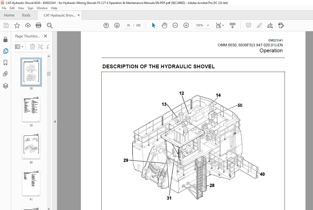
DESCRIPTION OF THE HYDRAULIC SHOVEL 2-6
Hydraulic shovel layout – upper structure 2-7
Hydraulic shovel layout – undercarriage and attachment 2-9
Undercarriage 2-10
Upper structure 2-10
Drive 2-10
Hydraulic system 2-10
Control and Monitoring Platform (CAMP) 2-10
EM023341
OMM 6030, 6030FS(3 847 020.01)-EN
TABLE OF CONTENTS
vi
Board-Control-System (BCS) 2-11
Demand control / Zero-flow regulation 2-11
Automatic reset to idling 2-11
Electrical system 2-11
Safety films and warning messages 2-12
ISO – compliant safety messages set 2-13
Safety messages (ISO) – Description 2-18
Additional messages (ISO) – Description 2-22
ANSI – compliant safety messages set 2-27
Safety messages (ANSI) – Description 2-32
Additional messages (ANSI) – Description 2-36
Entering and leaving the machine – Safety instructions 2-40
Access ladder – lighting 2-40
Access ladder – function 2-41
Emergency exit in operator’s cab and escape ladder 2-42
Switching the cab interior lighting on and off 2-43
Switching the maintenance lights on and off 2-44
Emergency shut-off function 2-45
Putting the machine back into operation, reset of emergency shut off function 2-46
Battery isolator switch, shutting off supply voltage 2-47
Starter isolator switch, shutting off starter voltage 2-47
Operator’s seat 2-48
Reducing the operators exposure to vibrations 2-50
Trainer’s / instructor’s seat 2-50
Fire extinguisher 2-51
Automatic fire-extinguishing system (optional) 2-51
Windscreen washer 2-52
Operating hours meter (if equipped) 2-52
Emergency escape device / seat (optional) 2-53
MONITORING, WARNING AND CONTROL ELEMENTS 2-56
Engine 1 (LH), control and monitoring 2-63
Engine 2 (RH), control and monitoring 2-65
PUTTING THE MACHINE INTO OPERATION 2-84
Electrical Storm Injury Prevention 2-84
Reducing the operator’s exposure to noise 2-84
Refuelling 2-85
Diesel fuel – recommendations 2-85
Back-up heating (option), filling in fuel 2-85
Service station (tanklift) 2-86
Emergency off switch 2-87
Switching the electrical system on and off 2-92
Engines, emergency shut-off 2-92
Preheating system for engine and hydraulic oil (optional) 2-93
Fuel preheating system (optional) 2-94
STARTING AND STOPPING THE ENGINES 2-96
Starting the engines 2-96
Starting the left-hand engine 2-96
Starting the right-hand engine 2-96
Engines – adjusting the speed 2-97
Starting the engines at low temperatures 2-97
EM023341
OMM 6030, 6030FS(3 847 020.01)-EN
TABLE OF CONTENTS
vii
Shutting off the engines 2-98
Shutting off the left-hand engine 2-98
Shutting off the right-hand engine 2-98
AIR CONDITIONER (OPTIONAL) 2-99
Back-up heating operator’s cab (optional) 2-100
Back-up heating (optional) 2-101
MAXIMUM MACHINE INCLINATIONS, INFORMATION 2-102
TRAVELING, SAFETY INSTRUCTIONS 2-104
TRAVELING 2-105
Upper structure basic position 2-105
Traveling forwards/backwards 2-105
Upper structure holding brake 2-109
Track parking brake 2-109
TRANSPORTING THE MACHINE 2-110
Transport – Safety instructions 2-110
WORKING OPERATION – SAFETY INSTRUCTIONS 2-111
WORKING OPERATION 2-113
Before starting work 2-113
Activating the electronic hydraulic shovel control (pilot control) 2-113
Swinging the upper structure 2-114
Braking the upper structure 2-114
Working operations 2-115
Engine-off attachment lowering 2-116
After daily operation 2-117
WORKING ON THE ATTACHMENT – SAFETY INSTRUCTIONS 2-118
Securing the machine 2-119
CORROSION PROTECTION FOR PINS AND BEARINGS (BUSHINGS AND HUBS) 2-120
ON-BOARD CRANE (OPTIONAL) 2-121
Monitoring, warning and control elements 2-121
On-board crane, putting into operation 2-122
On-board crane, drive unit 2-122
On-Board crane, – blocking the boom in position of rest 2-123
Checking the on-board crane 2-123
MONITORING CAMERAS (OPTIONAL) 2-124
Monitoring cameras – function 2-124
NOTES 2-125
3 INSPECTION AND SERVICING 3-1
INSPECTION AND SERVICING – SAFETY INSTRUCTIONS 3-3
INSPECTION AND SERVICING WORK, FIRE AND EXPLOSION HAZARD 3-7
INSPECTION AND SERVICING PLANS – INSTRUCTIONS 3-9
C27 Engine Maintenance Interval Schedule – Notes 3-10
Plan V 3-11
EM023341
OMM 6030, 6030FS(3 847 020.01)-EN
TABLE OF CONTENTS
viii
Plan N 3-13
Plan T and W 3-15
Plan A – E 3-17
LUBRICATING CHART – GREASE 3-24
Lubricating chart – Grease (legend) 3-25
Filling quantities – Grease 3-25
INSPECTION PLAN – OIL 3-26
Inspection plan – Oil (legend) 3-27
Engine oil service interval table 3-28
Engine oil service interval table (with Reserve™ Oil Tank) 3-29
Filling quantities – oil 3-30
Filling quantities – other 3-30
LUBRICANTS / CONSUMABLES 3-31
Notes on the selection of oils and greases 3-31
Avoid mixing of different hydraulic fluids 3-31
I. Oils for combustion engines 3-32
II. Fluid for hydraulic system 3-33
III.a Oils for pump drive gearboxes and travel gearboxes 3-34
III.b Oil for swing gearboxes 3-35
V. Grease for bearings, slew rings and track system (Central lubrication system) 3-36
Grease for idlers, track rollers and upper rollers (Lifetime lubrication) 3-37
Coolant for use on all combustion engines 3-38
SERVICING WORK 3-39
Hose line for oil and cooling liquid changes 3-39
ENGINE 3-40
Engine – Safety instructions 3-40
Walk-Around Inspection 3-41
Belts – Inspect/Adjust/Replace 3-42
Fuel Injector – Inspect/Adjust 3-43
Engine Mounts – Inspect 3-43
Engine Oil Sample – Obtain 3-44
Engine Valve Lash – Check 3-45
Engine Valve Rotators – Inspect 3-45
Coolant Temperature Regulator – Replace 3-46
Engine Hoses and Clamps – Inspect/Replace 3-47
Engine oil – checking the level / topping up 3-50
Engine oil reservoir (optional) – checking the oil level / topping up 3-51
Engine oil – change 3-52
Engine oil reservoir (optional), draining the oil off 3-54
Engine oil filter – replace 3-56
Engine oil reservoir (optional) – replacing the oil filters 3-56
Engine crankcase breather 3-57
Engine crankcase breather – clean 3-57
Engine crankcase breathers – clean 3-57
Cold-starting fluid (ether) – Replacing the pressure vessel 3-58
COOLING SYSTEM 3-59
Temperature 3-59
Radiators 3-60
EM023341
OMM 6030, 6030FS(3 847 020.01)-EN
TABLE OF CONTENTS
ix
Cooling-liquid level check 3-60
Cooling liquid – change 3-63
Coolant Extender (ELC) – Add 3-65
Coolant Sample (Level 1) – Obtain 3-66
Coolant Sample (Level 2) – Obtain 3-67
Cooling System Supplemental Coolant Additive (SCA) – Test/ Add 3-68
AIR-INTAKE SYSTEM 3-70
Dust trap – cleaning 3-70
Main filter elements 3-71
Main filter elements – checking and cleaning 3-72
Secondary filter element – replace 3-73
Air-intake lines – inspect 3-73
FUEL SYSTEM 3-74
Fuel system – Safety instructions 3-74
Fuel filter – replace 3-74
Primary fuel filter – drain water 3-75
Primary fuel filter – replace 3-75
Fuel system – vent 3-76
Fuel tanks – clean 3-76
Water trap (optional) – clean, replace 3-78
Fuel System – Prime 3-79
ELECTRICAL SYSTEM 3-80
Electrical system – Safety instructions 3-80
Alternator – Instructions 3-80
Electrical circuit diagrams 3-80
Electrical system switch-cabinets 3-80
Lamps and bulbs – replace 3-80
Battery – check state of charge 3-81
Charging batteries inside the machine, safety instructions 3-82
Battery – removing and installing 3-83
Switchgear cabinet – aeration 3-84
Xenon floodlight projector – replacing the lamp 3-86
Lighting systems in LED technonogy – instructions 3-88
HYDRAULIC SYSTEM 3-89
Hydraulic system – Safety instructions 3-89
Hydraulic system – depressurize 3-89
Hydraulic oil level – check 3-90
Replacing the hydraulic oil return-flow filter (hydraulic oil reservoir), old version 3-92
Replacing the hydraulic oil return-flow filter (hydraulic oil reservoir), new version 3-95
Bypass valves (hydraulic oil reservoir), checking / cleaning 3-97
Replacing the bypass valves and sealing rings 3-97
Replacing the hydraulic oil return-flow filters (filter housing cooling system) 3-98
Bypass valves (filter housing – cooling system), checking / replacing 3-99
Breather filter, replace 3-100
Filter (servo control circuit) 3-101
High-pressure filter for working hydraulics – check for contamination and damage 3-102
High-pressure filter for working hydraulics – replace 3-103
High-pressure filters for swing circuit – check for contamination and damage 3-104
High-pressure filters for swing circuit – replace 3-105
EM023341
OMM 6030, 6030FS(3 847 020.01)-EN
TABLE OF CONTENTS
x
Filter pump control, clean 3-106
Changing the hydraulic oil 3-107
Avoid mixing of different hydraulic fluids 3-107
Venting the hydraulic system 3-111
Hydraulic oil cooler – Clean 3-112
Electronic hydraulic shovel control, clean / lubricate 3-113
Pressure accumulator – Emergency lowering 3-114
PUMP TRANSFER GEARBOX 3-115
Pump gearbox, checking the oil level / Topping up with oil 3-115
Pump transfer gearbox oil sample – obtain 3-116
Pre-chambers – checking oil level / topping up with oil 3-116
Pump gearbox – changing the gearbox oil 3-117
Pre-chambers – changing the gearbox oil 3-118
Pump drive gearbox breather valve – replace 3-118
Pump transfer gearbox lube oil filters 3-120
SWING GEARBOX 3-121
Swing gearbox oil sample – obtain 3-121
Swing gearbox – checking the oil level / Topping up with oil 3-121
Swing gearbox – changing oil 3-122
Swing gearbox venting 3-122
SWING GEARBOX 3-123
Swing gearbox, checking the oil level / Topping up with oil 3-123
Swing gearbox, changing oil 3-124
Swing gearbox, venting 3-125
TRAVEL GEARBOX P/N 2712182 3-126
Travel gearbox, checking the oil level / Topping up with oil 3-126
Travel gearbox, changing oil 3-127
Pre-chamber / spur gear section, Changing the oil 3-127
Brake chamber, Changing oil 3-128
Travel Gearbox Oil Sample – Obtain 3-128
Breather filter – replace 3-128
TRAVEL GEARBOX P/N 3683493 AND 3737455 3-129
Travel gearbox – Checking the oil level / Topping up with oil 3-129
Brake chamber – Checking the oil level / Topping up with oil 3-129
Travel gearbox – Changing oil 3-130
Brake chamber – Changing oil 3-131
Travel Gearbox Oil Sample – Obtain 3-131
Breather filter 3-131
CRAWLER TRACKS 3-132
Track roller fastening – check 3-132
Upper roller fastening – check 3-132
Undercarriage – check for leaks and free movement 3-132
Track roller – lubricating 3-133
Track roller (Part no. 3751860) – check grease level 3-134
Track tensioning system 3-135
Pressure-accumulator inspection regulations 3-136
Checking the gas charging pressure in the pressure accumulator 3-136
EM023341
OMM 6030, 6030FS(3 847 020.01)-EN
TABLE OF CONTENTS
xi
SWING RING 3-137
Swing ring – Instructions 3-137
Bearing races 3-137
CENTRAL LUBRICATING SYSTEM 3-139
Design 3-139
Function 3-140
Grease container – filling up 3-141
Breather filter grease container – check / replace 3-141
Greasing pressure – Checking 3-142
Grease line – unblocking 3-142
Oilfilter (hydraulic circuit grease pump) – replace 3-143
Grease filter (filling the grease container) – check / replace 3-144
Grease filter (Grease lines) – check / replace 3-145
OTHER MAINTENANCE 3-146
Engine – Clean 3-146
Travel Alarm – Test 3-146
Radiator – Clean 3-147
Aftercooler Core – Clean/Test 3-148
Air conditioning filter – clean 3-148
Reservoirs for used grease at the A-frame, emptying 3-149
Hydraulic ladder, pressure accumulator 3-149
Pressure-accumulator inspection regulations 3-150
Extract from the German regulations 3-150
Checking the gas charging pressure in the pressure accumulator 3-150
Attachment – check for cracks 3-151
Clam cylinder chamber – check for soiling 3-151
Window panes – Clean 3-152
Mirror – Check/Clean/Adjust 3-152
Cameras – Check/Clean/Adjust (If equipped) 3-153
Horn – Inspect / Replace 3-154
Seat belt – inspect 3-155
Seat belt – replace 3-155
ON-BOARD CRANE, DRIVE UNIT (OPTIONAL) 3-156
On-board crane – lubricating 3-156
On-Board crane – checking tightness of fastening bolts 3-157
PUTTING THE HYDRAULIC SHOVEL OUT OF OPERATION AND RECOMMISSIONING 3-158
Hydraulic shovel – putting out of operation 3-158
Battery – storage 3-158
Hydraulic shovel – recommissioning 3-158
EM023341
OMM 6030, 6030FS(3 847 020.01)-EN
TABLE OF CONTENTS
xii
NOTES 3-159
4 REPAIR WORK 4-1
REPAIR WORK – SAFETY INSTRUCTIONS 4-3
CONFINED SPACES – SAFETY INSTRUCTIONS 4-4
REPAIR WORK, FIRE AND EXPLOSION HAZARD 4-5
REPAIR WORK, ENGINE 4-6
Overhaul Considerations 4-6
Overhaul Recommendation 4-7
HALF LIFE 4-9
FULL LIFE 4-10
Cleaning of Components 4-11
HYDRAULIC SYSTEM 4-12
Repair instructions 4-12
Hydraulic hoses – Instructions 4-12
PRESSURE ACCUMULATORS – SAFETY INSTRUCTIONS 4-13
WELDING AND FLAME CUTTING WORKS – SAFETY INSTRUCTIONS 4-14
DISPOSAL AT THE END OF THE SERVICE LIFE 4-17
Appropriate disposal of batteries 4-18
NOTES 4-19
5 ANNEX 5-1
BOARD-CONTROL-SYSTEM 5-3
BCS III, what’s that? 5-3
SIL2 functionality 5-3
The keys on the front side 5-4
Other elements on the front side 5-4
BCSIII, the start screen 5-5
Information given on the start screen, top section 5-6
Information given on the start screen, central section 5-7
Information given on the start screen, lower section 5-8
EMERGENCY STOP, RESET FUNCTION 5-9
SWING CIRCUIT LOCK-OUT FUNCTION 5-10
Information given on the “Service” screen 5-11
Engine data screen 5-12
Hydraulic data screen 5-13
Lubrication data screen 5-14
Controls adjustment data screen 5-15
View documents screen 5-16
Signal table screen 5-17
Signal table screen, location 5-18
Signal table screen, diagram 5-19
Signal table screen, diagram configuration 5-20
Code table screen 5-21
EM023341
OMM 6030, 6030FS(3 847 020.01)-EN
TABLE OF CONTENTS
xiii
SLEW BRAKE TEST SCREEN 5-22
BCS III, interfaces 5-23
USB interface, data storage 5-23
Saving data to a USB stick 5-24
Saving data to a USB stick, continued 5-25
Saving data to a USB stick, continued 5-26
BCSIII, cleaning 5-27
BCSIII, disposal 5-27
TROUBLESHOOTING 5-28
Instructions on troubleshooting 5-28
Layout of the fault table 5-28
Possible causes 5-28
Measures 5-28
Section 5-28
FAULT TABLES 5-29
Combustion engine – Fault table 5-29
Working hydraulics – Fault table 5-30
Track drive – Fault table 5-31
Swing mechnism – Fault table 5-32
Central lubricating system – Fault table 5-33
ENGINE MONITORING, CONTROL LAMPS 5-34
HYDRAULIC CIRCUIT DIAGRAM 5-35
ABBREVIATIONS 5-36
ABBREVIATIONS 5-37
PRODUCT SPECIFICATION SHEET 5-38
NOTES 5-39
6 INDEX 6-1
Questions? Email us: [email protected]
https://vimeo.com/857522179?share=copy
PLEASE NOTE:
- This is the same manual used by the DEALERSHIPS to SERVICE your vehicle.
- The manual can be all yours – Once payment is complete, you will be taken to the download page from where you can download the manual. All in 2-5 minutes time!!
- Need any other service / repair / parts manual, please feel free to contact us at heydownloadss @gmail.com . We may surprise you with a nice offer
S.V