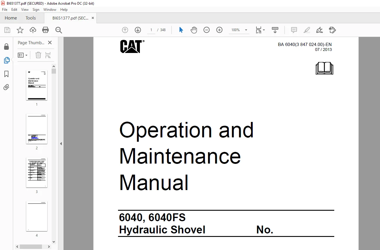
Cat 6040, 6040FS Hydraulic Shovel Operation and Maintenance Manual BI651377 – PDF DOWNLOAD
$29.95
Cat 6040, 6040FS Hydraulic Shovel Operation and Maintenance Manual BI651377 – PDF DOWNLOAD
Description
Cat 6040, 6040FS Hydraulic Shovel Operation and Maintenance Manual BI651377 – PDF DOWNLOAD
FILE DETAILS:
Cat 6040 6040FS Hydraulic Shovel Operation and Maintenance Manual BI651377 – PDF DOWNLOAD
Language : English
Pages : 348
Downloadable : Yes
File Type : PDF
DESCRIPTION:
Cat 6040 6040FS Hydraulic Shovel Operation and Maintenance Manual BI651377 – PDF DOWNLOAD
PREFACE
- These operating instructions are designed to familiarize the operator with the machine and its designated use. The operating instructions contain important information on how to operate the machine safely, properly and with maximum efficiency.
- Observing these instructions helps to prevent hazardous situations, to reduce repair costs and downtimes and to increase the reliability and service life of the machine. The operating instructions must be supplemented by the respective national rules and regulations for accident prevention and environmental protection.
- The operating instructions must always be available in the driver’s cab of the machine. The operating instructions must be read and put into practice by any person in charge of carrying out work with or on the machine, such as
- The Bucyrus HEX after-sales service will be pleased to deal with any queries you may have after reading through the operating instructions.
- All Bucyrus HEX operating manuals are issued in German and then translated. Even a good translation may give rise to questions which Bucyrus HEX will be pleased to answer.
- The operating instructions are not work instructions for carrying out major repairs. Such work is willingly done for you by the Bucyrus HEX aftersales service
IMAGES PREVIEW OF THE MANUAL:
TABLE OF CONTENTS:
Cat 6040 6040FS Hydraulic Shovel Operation and Maintenance Manual BI651377 – PDF DOWNLOAD
1 INTRODUCTION 1-1
PREFACE _____ 1-1
Further machine documentation 1-1
WARRANTY ____ 1-2
FUNDAMENTAL SAFETY INSTRUCTIONS ______ 1-3
Warnings and symbols 1-3
DESIGNATED USE, UNAUTHORIZED USE _____ 1-4
Noise emission information ____ 1-5
Vibration information _ 1-5
ORGANIZATIONAL MEASURES 1-6
Selection and qualification of personnel; basic responsibilities_____ 1-7
Safety instructions governing specific operational phases 1-7
Special work in conjunction with utilization of the machine and maintenance and repairs as well as
troubleshooting during work; disposal of parts and consumables___ 1-8
Warning of special dangers ____ 1-9
Gas, dust, steam and smoke ___ 1-9
Hydraulic equipment 1-10
FIRE AND EXPLOSION HAZARD _____ 1-11
NOTES _ 1-13
2 OPERATION ___ 2-1
OPERATION – SAFETY INSTRUCTIONS 2-3
Operation and Maintenence Manual, where to store it in the operator’s cab 2-4
FIRE AND EXPLOSION HAZARD 2-5
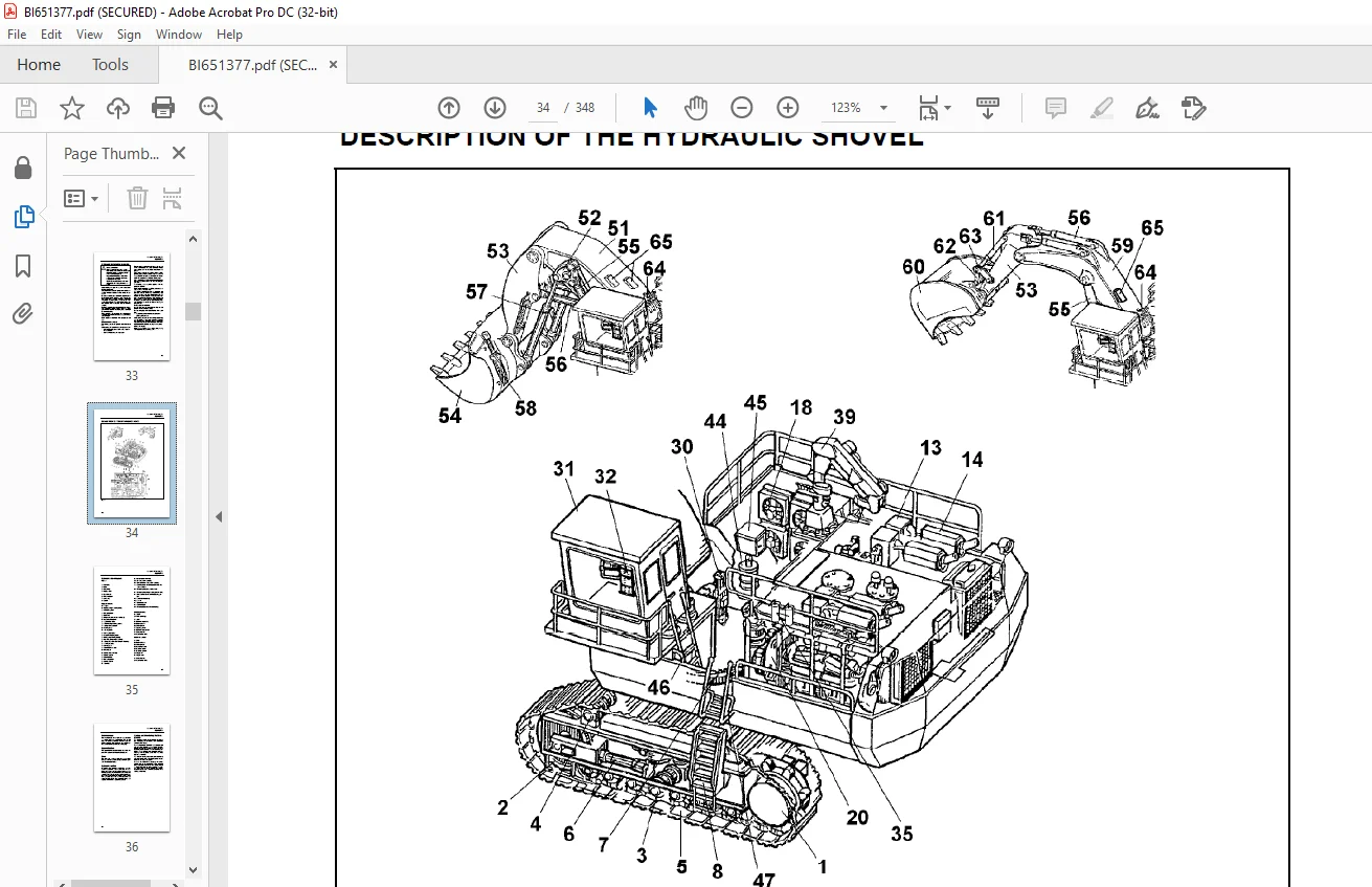
DESCRIPTION OF THE HYDRAULIC SHOVEL ___ 2-6
Hydraulic shovel layout 2-7
Undercarriage _ 2-8
Upperstructure 2-8
Drive __ 2-8
Hydraulic system ____ 2-8
Control and Monitoring Platform (CAMP) 2-8
Board-Control-System (BCS) __ 2-9
Demand control / Zero-flow regulation _ 2-9
Automatic reset to idling ______ 2-9
Electrical system ____ 2-9
Signs _ 2-10
Entering and leaving the machine Safety instructions___ 2-18
Access ladder lighting 2-18
Swinging ladder (optional) ____ 2-19
Folding ladder 2-20
Emergency exit in operator’s cab and escape ladder ___ 2-21
Switching the cab interior lighting on and off____ 2-22
Switching the maintenance lights on and off ____ 2-23
Emergency shut-off function __ 2-24
BA 6040(3 847 024.00)-EN
TABLE OF CONTENTS
vi
Putting the machine back into operation, reset of emergency shut off function __ 2-25
Battery isolator switch, shutting off supply voltage _____ 2-26
Starter isolator switch, shutting off starter voltage 2-26
Operator’s seat ____ 2-27
Reducing the operators exposure to vibrations__ 2-29
Trainer’s / instructor’s seat ___ 2-29
Fire extinguisher ___ 2-30
Automatic fire-extinguishing system (optional) __ 2-31
Windscreen washer _ 2-31
Operating hours meter ______ 2-31
Emergency escape device / seat (optional) ____ 2-32
MONITORING, WARNING AND CONTROL ELEMENTS_ 2-36
Engine 1 (LH), control and monitoring _ 2-43
Engine 2 (RH), control and monitoring 2-45
PUTTING THE MACHINE INTO OPERATION ___ 2-64
Reducing the operator’s exposure to noise_____ 2-64
Refuelling ___ 2-65
Back-up heating (option), filling in fuel 2-65
Service station (tanklift) ______ 2-66
Emergency off switch 2-67
Switching the electrical system on and off _____ 2-72
Engines, emergency shut-off __ 2-72
Preheating system for engine and hydraulic oil (optional) 2-73
Fuel preheating system (optional) ____ 2-74
STARTING AND STOPPING THE ENGINES ____ 2-76
Starting the engines 2-76
Starting the left-hand engine __ 2-76
Starting the right-hand engine _ 2-76
Engines – adjusting the speed 2-77
Starting the engines at low temperatures ______ 2-77
Shutting off the engines ______ 2-78
Shutting off the left-hand engine _____ 2-78
Shutting off the right-hand engine ____ 2-78
AIR CONDITIONER (OPTIONAL) _____ 2-79
Back-up heating operator’s cab (optional)______ 2-80
Back-up heating (optional) ___ 2-81
MAXIMUM MACHINE INCLINATIONS, INFORMATION__ 2-82
TRAVELLING, SAFETY INSTRUCTIONS 2-84
TRAVELLING __ 2-85
Upperstructure basic position _ 2-85
Travelling forwards/backwards 2-85
Upperstructure holding brake _ 2-89
Track parking brake 2-89
TRANSPORTING THE MACHINE _____ 2-90
Transport – Safety instructions 2-90
BA 6040(3 847 024.00)-EN
TABLE OF CONTENTS
vii
WORKING OPERATION – SAFETY INSTRUCTIONS ___ 2-91
WORKING OPERATION ______ 2-93
Before starting work 2-93
Activating the electronic hydraulic shovel control 2-93
Swinging the upperstructure __ 2-94
Braking the upperstructure ___ 2-94
Working _____ 2-95
Emergency lowering of the working equipment__ 2-96
After daily operation 2-97
ASSEMBLING WORKING EQUIPMENT – SAFETY INSTRUCTIONS _____ 2-98
Securing the machine 2-99
CORROSION PROTECTION FOR PINS AND BEARINGS (BUSHINGS AND HUBS)_____ 2-100
ON-BOARD CRANE (OPTIONAL) ____ 2-101
Monitoring, warning and control elements_____ 2-101
On-board crane, putting into operation 2-102
On-board crane, drive unit ___ 2-102
On-Board crane, – blocking the boom in position of rest 2-103
Checking the on-board crane 2-103
MONITORING CAMERAS (OPTIONAL) 2-104
Monitoring cameras – function _____ 2-104
NOTES 2-105
3 INSPECTION AND SERVICING _ 3-1
INSPECTION AND SERVICING – SAFETY INSTRUCTIONS 3-3
INSPECTION AND SERVICING WORK, FIRE AND EXPLOSION HAZARD _ 3-7
INSPECTION AND SERVICING PLANS – INSTRUCTIONS 3-9
Plan V 3-11
Plan N 3-13
Plan T and W _ 3-15
Plan A – E ___ 3-17
LUBRICATING CHART – GREASE ____ 3-26
Lubricating chart – Grease (legend) __ 3-27
Filling quantities – Grease ____ 3-27
INSPECTION PLAN – OIL _____ 3-28
Inspection plan – Oil (legend) _ 3-29
Filling quantities – oil 3-30
Filling quantities – other _____ 3-30
LUBRICANTS / CONSUMABLES _____ 3-31
Notes on the selection of oils and greases _____ 3-31
Avoid mixing of different hydraulic fluids 3-31
I. Oils for combustion engines _____ 3-32
II. Fluid for hydraulic system _____ 3-33
III.a Oils for pump drive gearboxes and travel gearboxes ____ 3-34
III.b Oil for swing gearboxes _____ 3-35
V. Grease for bearings, swing rings and track system (Central lubrication system) ____ 3-36
BA 6040(3 847 024.00)-EN
TABLE OF CONTENTS
viii
Grease for idlers, track rollers and support rollers (Lifetime lubrication) ___ 3-37
Coolant for use on all combustion engines _____ 3-38
SERVICING WORK __ 3-39
Hose line for oil and cooling liquid changes ____ 3-39
ENGINE 3-40
Engine – Safety instructions ___ 3-40
Engine oil, checking the level / topping up _____ 3-41
Engine oil reservoir (optional), checking the oil level / topping up__ 3-42
Engine oil, change __ 3-43
Engine oil reservoir (optional), draining the oil off 3-45
Engine oil filter, replace ______ 3-47
Engine oil reservoir (optional), replacing the oil filters___ 3-48
Centrifuge (optional) 3-49
Eliminator filter and centrifuge (optional) 3-50
Cold-starting fluid (ether) – Replacing the pressure vessel 3-52
COOLING SYSTEM __ 3-53
Temperature _ 3-53
Radiators ____ 3-53
Cooling-liquid level check ____ 3-54
Cooling-liquid, select 3-54
Cooling liquid, topping up ____ 3-55
Cooling liquid, change 3-57
Testing the cooling liquid composition _ 3-59
Water filter, replace _ 3-60
AIR-INTAKE SYSTEM 3-61
Main filter elements, removal and installation ___ 3-62
Main filter elements, checking and cleaning ____ 3-63
Secondary filter element, replace ____ 3-64
Air-intake lines 3-65
Dust collection 3-65
FUEL SYSTEM 3-66
Fuel system – Safety instructions ____ 3-66
Fuel filter, replace __ 3-66
Breather filter fuel tank, replace _____ 3-67
Fuel tanks, cleaning 3-67
Water trap (optional) 3-69
ELECTRICAL SYSTEM 3-71
Electrical system – Safety instructions _ 3-71
Alternator – Instructions ______ 3-71
Electrical circuit diagrams ____ 3-71
Electrical system switch-cabinets ____ 3-71
Replacing lamps and bulbs ___ 3-71
Battery 3-72
Charging batteries inside the machine, safety instructions 3-73
Removing and installing the battery __ 3-74
Switchgear cabinet, aeration __ 3-75
Xenon floodlight projector, replacing the lamp __ 3-77
Lighting systems in LED technonogy, instructions _____ 3-79
BA 6040(3 847 024.00)-EN
TABLE OF CONTENTS
ix
HYDRAULIC SYSTEM 3-80
Hydraulic system – Safety instructions 3-80
Depressurizing the hydraulic system __ 3-80
Checking the hydraulic oil level 3-81
Hydraulic oil return-flow filters (hydraulic oil reservoir), replace ___ 3-83
Hydraulic oil return-flow filters (hydraulic oil reservoir), replace (from machine no. 170130) 3-86
Bypass valves (hydraulic oil reservoir), checking / cleaning ______ 3-88
Replacing the bypass valves and sealing rings__ 3-88
Replacing the hydraulic oil return-flow filters (filter housing cooling system) ____ 3-89
Bypass valves (filter housing – cooling system), checking / replacing_____ 3-90
Breather filter, replace 3-91
Filter (servo control circuit and auxiliary control circuit)__ 3-92
High-pressure filter for working hydraulics, replace ____ 3-93
High-pressure filters for the servo circuit, replace 3-94
High-pressure filters for feeding circuits and swing pumps, replace 3-95
Filter pump control, clean ____ 3-96
Changing the hydraulic oil ____ 3-97
Avoid mixing of different hydraulic fluids 3-97
Venting the hydraulic system 3-101
Cleaning the hydraulic oil cooler ____ 3-102
Electronic hydraulic shovel control, clean / lubricate___ 3-103
Pressure accumulator – Emergency lowering __ 3-104
PUMP TRANSFER GEARBOX 3-105
Pump gearbox, checking the oil level / Topping up with oil______ 3-105
Pump gearbox, change oil ___ 3-106
Pump gearbox, change oil ___ 3-106
Pump gearbox, venting _____ 3-107
Pump transfer gearbox lube oil filters 3-108
SWING GEARBOX _ 3-109
Swing gearbox, checking the oil level / Topping up with oil _____ 3-109
Swing gearbox venting _____ 3-109
Changing the swing gearbox oil ____ 3-110
TRAVEL GEARBOX (PN 2763213) ___ 3-112
Travel gearbox – Checking the oil level / Topping up with oil ____ 3-112
Pre-chamber / spur wheel section, Check the oil level / Top up with oil __ 3-112
Hydraulic motor chamber – Check the oil level / Top up with oil __ 3-112
Travel gearbox, Changing oil 3-113
Pre-chamber / spur wheel section, Changing oil 3-113
Hydraulic motor chamber, Changing oil ______ 3-114
Travel gearbox breather filter, Clean / Replace_ 3-114
TRAVEL GEARBOX (PN 3719869) ___ 3-115
Travel gearbox – Checking the oil level / Topping up with oil ____ 3-115
Hydraulic motor chambers, Check the oil level / Top up with oil __ 3-115
Travel gearbox, Changing oil 3-116
Hydraulic motor chambers, Changing oil _____ 3-116
CRAWLER TRACKS 3-117
Undercarriage, lubricating system ___ 3-117
Track roller, Support roller ___ 3-118
Track tensioner ___ 3-119
BA 6040(3 847 024.00)-EN
TABLE OF CONTENTS
x
Pressure-accumulator inspection regulations __ 3-120
Checking the gas charging pressure in the pressure accumulator 3-120
SWING RING _ 3-121
Swing ring – Instructions ____ 3-121
Bearing races ____ 3-121
CENTRAL LUBRICATING SYSTEM __ 3-123
Design _____ 3-123
Function ___ 3-124
Filling up the grease container _____ 3-125
Breather filter grease container, check / replace 3-125
Checking the greasing pressure ____ 3-126
Unblocking a grease line ____ 3-126
Oilfilter replace (hydraulic circuit grease pump) 3-127
Grease filter replace (filling the grease container)_____ 3-128
Grease filter replace (Grease lines) _ 3-128
OTHER MAINTENANCE _____ 3-129
Engine _____ 3-129
Heating and air conditioning _ 3-129
Reservoirs for used grease at the A-frame, emptying__ 3-130
Hydraulic ladder, pressure accumulator ______ 3-130
Pressure-accumulator inspection regulations __ 3-131
Extract from the German regulations 3-131
Checking the gas charging pressure in the pressure accumulator 3-131
ON-BOARD CRANE, DRIVE UNIT ___ 3-132
On-board crane, greasing ___ 3-132
On-Board crane, checking tightness of fastening bolts_ 3-133
PUTTING THE EXCAVATOR OUT OF OPERATION AND RECOMMISSIONING 3-134
Putting the hydraulic shovel out of operation __ 3-134
Battery storage ___ 3-134
Recommissioning _ 3-134
NOTES 3-135
4 REPAIR WORK _ 4-1
REPAIR WORK – SAFETY INSTRUCTIONS______ 4-3
CONFINED SPACES – SAFETY INSTRUCTIONS _ 4-4
REPAIR WORK, FIRE AND EXPLOSION HAZARD 4-5
REPAIR WORK, ENGINE ______ 4-6
HYDRAULIC SYSTEM _ 4-7
Repair instructions __ 4-7
Hydraulic hoses – Instructions _ 4-7
BA 6040(3 847 024.00)-EN
TABLE OF CONTENTS
xi
PRESSURE ACCUMULATORS – SAFETY INSTRUCTIONS 4-8
WELDING AND FLAME CUTTING WORKS – SAFETY INSTRUCTIONS ___ 4-9
DISPOSAL AT THE END OF THE SERVICE LIFE 4-12
Appropriate disposal of batteries _____ 4-13
NOTES _ 4-15
5 ANNEX __ 5-1
BOARD-CONTROL-SYSTEM ___ 5-3
BCS III, what’s that? _ 5-3
SIL2 functionality ____ 5-3
The keys on the front side _____ 5-4
Other elements on the front side 5-4
BCSIII, the start screen 5-5
Information given on the start screen, top section_ 5-6
Information given on the start screen, central section____ 5-7
Information given on the start screen, lower section _____ 5-8
EMERGENCY STOP, RESET FUNCTION 5-9
SWING CIRCUIT LOCK-OUT FUNCTION ______ 5-10
Information given on the “Service” screen______ 5-11
Engine data screen _ 5-12
Hydraulic data screen 5-13
Lubrication data screen ______ 5-14
Controls adjustment data screen _____ 5-15
View documents screen _____ 5-16
Signal table screen _ 5-17
Signal table screen, location __ 5-18
Signal table screen, diagram __ 5-19
Signal table screen, diagram configuration _____ 5-20
Code table screen __ 5-21
SLEW BRAKE TEST SCREEN _ 5-22
BCS III, interfaces __ 5-23
USB interface, data storage __ 5-23
Saving data to a USB stick ___ 5-24
Saving data to a USB stick, continued 5-25
Saving data to a USB stick, continued 5-26
BCSIII, cleaning ____ 5-27
BCSIII, disposal ____ 5-27
TROUBLESHOOTING 5-28
Instructions on troubleshooting 5-28
Layout of the fault table ______ 5-28
Possible causes ___ 5-28
Measures ___ 5-28
Section _____ 5-28
FAULT TABLES 5-29
Combustion engine – Fault table _____ 5-29
Working hydraulics – Fault table _____ 5-30
BA 6040(3 847 024.00)-EN
TABLE OF CONTENTS
xii
Track drive – Fault table _____ 5-31
Swing mechnism – Fault table 5-32
Central lubricating system – Fault table 5-33
ENGINE ELECTRONIC UNIT, DISPLAYING STORED FAULT CODES ___ 5-34
Engine electronics, displaying faults __ 5-34
Engine electronic, displaying faults in memory __ 5-34
HYDRAULIC CIRCUIT DIAGRAM _____ 5-35
ABBREVIATIONS ___ 5-36
ABBREVIATIONS __ 5-37
PRODUCT SPECIFICATION SHEET ___ 5-2
NOTES __ 5-3
6 INDEX __ 6-1
Contact us: [email protected]
https://vimeo.com/848657110?share=copy
PLEASE NOTE:
- This is the same manual used by the dealers to diagnose and troubleshoot your vehicle
- You will be directed to the download page as soon as the purchase is completed. The whole payment and downloading process will take anywhere between 2-5 minutes
- Need any other service / repair / parts manual, please feel free to contact [email protected] . We still have 50,000 manuals unlisted
S.M