CAT 6040, 6040FS Hydraulic Shovel Operation & Maintenance Manual DHX40010 DHX40012 – PDF DOWNLOAD
$28.95
CAT 6040, 6040FS Hydraulic Shovel Operation & Maintenance Manual DHX40010 DHX40012 – PDF DOWNLOAD
Description
CAT 6040, 6040FS Hydraulic Shovel Operation & Maintenance Manual DHX40010 DHX40012 – PDF DOWNLOAD
FILE DETAILS:
CAT 6040, 6040FS Hydraulic Shovel Operation & Maintenance Manual DHX40010 DHX40012 – PDF DOWNLOAD
Language : English
Pages : 238
Downloadable : Yes
File Type : PDF
DESCRIPTION:
CAT 6040, 6040FS Hydraulic Shovel Operation & Maintenance Manual DHX40010 DHX40012 – PDF DOWNLOAD
Preface:
- These operating instructions are designed to fa- miliarize the operator with the machine
and its designated use. - The instruction manual contains important infor- mation on how to operate the machine
safely, properly and with maximum efficiency. Observing these instructions helps to
prevent hazardous situations, to reduce repair costs and downtimes and to increase the
reliability and service life of the machine. - The instruction manual must be supplemented by the respective national rules and regulations
for accident prevention and environmental protection. - The operating instructions must always be avail- able in the operator’s cab of the machine.
The operating instructions must be read and put into practice by any person in charge
of carrying out work with or on the machine, such as
– operation, including setting-up, troubleshooting in the course of work, care,
evacuation of pro- duction waste and disposal of fuels and con- sumables.
– maintenance (inspection, servicing, repair) and
/ or
– transport.
- In addition to the operating instructions and the mandatory rules and regulations for
accident pre- vention and environmental protection in the user’s country and at the place where the
machine is to be used, the generally recognized technical rules for safe and proper
working must be observed. [1]
The operating instructions are directed to the con- struction-machine specialist. They cannot
provide basic know-how. This can be acquired, for exam- ple, in several days’ instruction by
a qualified O&K mechanic or by attending an O&K training course for operators or
maintenance personnel. - The O&K after-sales service will be pleased to deal with any queries you may have after
reading through the operating instructions. - All O&K operating manuals are issued in German and then translated. Even a good translation may
give rise to questions which O&K will be pleased to answer. - The operating instructions are not work instruc- tions for carrying out major repairs. Such
work is willingly done for you by the O&K after-sales service. - The documentation relating to the machine is list- ed according to scope, quantity and
language in the shipping note of the machine or in the cover- ing letter if supplied
separately. The operating instructions and spare-parts list are marked with the serial
number of the machine. - On taking receipt of the consignment, please check that the documentation is
complete and in the language requested by you.
TABLE OF CONTENTS:
CAT 6040, 6040FS Hydraulic Shovel Operation & Maintenance Manual DHX40010 DHX40012 – PDF DOWNLOAD
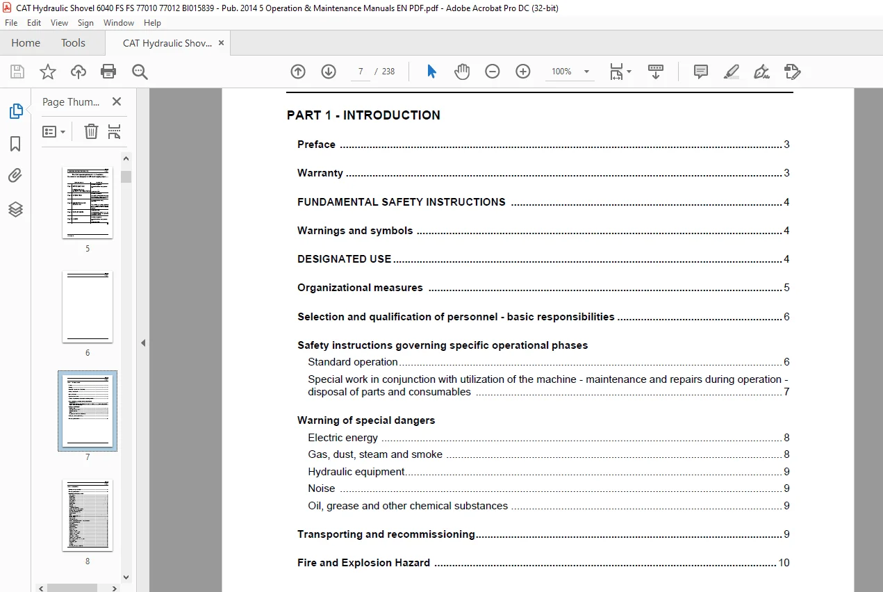
PART 1 – INTRODUCTION
Preface 3
Warranty 3
FUNDAMENTAL SAFETY INSTRUCTIONS 4
Warnings and symbols 4
DESIGNATED USE 4
Organizational measures 5
Selection and qualification of personnel – basic responsibilities 6
Safety instructions governing specific operational phases
Standard operation 6
Special work in conjunction with utilization of the machine – maintenance and repairs during operation –
disposal of parts and consumables 7
Warning of special dangers
Electric energy 8
Gas, dust, steam and smoke 8
Hydraulic equipment 9
Noise 9
Oil, grease and other chemical substances 9
Transporting and recommissioning 9
Fire and Explosion Hazard 10
BI015839
PART 2 – OPERATION
Operation – Safety instructions 13
Fire and Explosion Hazard 15
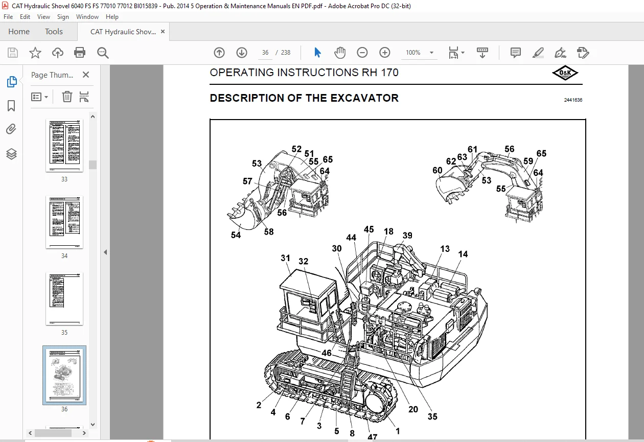
DESCRIPTION OF THE EXCAVATOR
Excavator layout 17
Undercarriage 17
Superstructure 17
Loading bucket 17
Backhoe bucket 17
Undercarriage 18
Superstructure 18
Drive unit 18
Hydraulic system 18
Pump-Managing-System 18
Demand control / Zero-flow regulation 18
Automatic engine speed reduction 18
Board-Control-System (BCS) 18
Electrical system 18
Signs 21
Warning and instruction signs 21
Machine number 21
Engine number 21
Component numbers 21
Entering and leaving the machine – Safety instructions 22
Ramp-type ladder (optional) 22
Ramp lighting 23
Superstructure lighting 23
Cab interior lamp 24
Windscreen washer 24
Driver’s seat 25
Adjusting the backrest 25
Adjusting the lumbar support 25
Adjusting the seat cushion 25
Adjusting the armrest 25
Fore-and-aft adjustment 25
Adjusting the seat suspension 25
Fore-and aft-adjustment of the seat plate 25
Fire-extinguisher 26
Extinguishing agent 26
Handling 26
Inspection 26
Fire extinguishing system (optional) 26
BI015839
Inspection 26
MONITORING, WARNING AND CONTROL ELEMENTS 28
PUTTING THE MACHINE INTO OPERATION 48
Refuelling
Refuelling – Safety instructions 48
Filling in fuel 48
Service station (tanklift) 48
Lowering the service station with the engines running 49
Raising the service station with the engines running 49
Refilling and draining 49
Measuring devices for fluids 50
Switching the electrical system on and off 53
Battery main switch 53
Starting and stopping the engines 54
Starting the engines 54
Starting the engines with the cold-starting aid 55
Shutting off the engines 55
Emergency – stop 55
Ventilation / heating
Heating 56
Ventilation 56
Heating 56
Air conditioner (optional) 57
Ventilation 57
Heating 57
Driving 59
TRAVELLING
Superstructure basic position 60
Travelling forwards/backwards 60
Regulating the travelling speed 61
Travelling uphill and downhill 61
Cornering 61
Turning 61
Note 62
Travelling over long distances 63
Emergency operation of track drive 64
Moving the excavator after a failure of the hydraulic system 64
Required equipment 64
Positioning both machines 65
Emergency travelling 66
BI015839
Locking the superstructure 67
Track parking brake 67
Transporting the machine
Transport – Safety instructions 68
Transport 68
Working operation – Safety instructions 69
WORKING OPERATION
Before starting work 71
Switching on the electronic excavator control 71
Slewing and braking the superstructure 71
Braking the superstructure 71
Working 72
Raising and lowering the boom 72
Extending and retracting the bucket or backhoe bucket stick 72
Filling and emptying the bucket or the backhoe 72
Opening and closing the bottom-dump bucket 72
Lowering the equipment in an emergency 72
After daily operation 73
Parking the machine 73
ASSEMBLING WORKING EQUIPMENT – SAFETY INSTRUCTIONS
Securing the machine 76
Corrosion protection for pins and bearings (bushings and hubs)
Part nos for Voler A C 77
Application of Voler A C 77
BI015839
PART 3 – INSPECTION AND SERVICING
Inspection and servicing – Safety instructions 81
Fire and Explosion Hazard 84
Inspection and servicing plans – Instructions
Intervals 87
Change of engine oil 87
Air-intake system 87
Oils / Greases 87
Cleaning jobs 87
Plan V 88
Plan N 90
Plan T 92
Plan W 92
Plan T 93
Plan W 93
Plan A 94
Plan B 94
Plan C 94
Plan D 94
Plan E 94
Plan A 95
Plan B 95
Plan C 95
Plan D 95
Plan E 95
Plan A 96
Plan B 96
Plan C 96
Plan D 96
Plan E 96
Plan A 97
Plan B 97
Plan C 97
Plan D 97
Plan E 97
Plan A 98
Plan B 98
Plan C 98
Plan D 98
Plan E 98
LUBRICATING CHART – GREASE (Loading bucket)
BI015839
Lubricating chart – Grease / Loading bucket 101
Refilling quantities – Grease 101
LUBRICATING CHART – GREASE (Backhoe bucket)
Lubricating chart – Grease / Backhoe bucket 103
Refilling quantities – Grease 103
INSPECTION PLAN – OIL
Inspection plan – Oil 105
Refilling quantities – Oil 106
Refilling quantities – Other 106
LUBRICANTS 107
Oils for combustion engines and compressors (selection) 107
Oils for hydraulic systems (selection) 108
Oils for gearboxes (selection) 109
Greases for bearings and slewing rings 110
Oils for refrigerating compressors 111
SERVICING WORK
Hose line for oil and cooling liquid changes 113
ENGINE
Engine – Safety instructions 114
Checking the V-belt tension 114
Retensioning the alternator/fan belt 114
Checking and adjusting the valve clearance 114
Checking the engine oil level / Topping up 114
Checking the oil level in the engine oil reservoir / topping up (optional) 115
Changing the engine oil 116
Draining off engine oil 116
Drawing off engine oil with the service station (optional equipment) 116
Filling in engine oil 117
Filling in engine oil through the service station (optional) 117
Changing the oil of the engine oil reservoir (optional ) 118
Draining off engine oil 118
Drawing off engine oil (optional) 118
Filling in engine oil 119
Replacing the engine oil filter 120
Main-flow oil filters 120
Bypass oil filters 120
Centrifuge (optional) 121
BI015839
COOLING SYSTEM
Temperature 122
Radiators 122
Cooling-liquid level 122
Topping up cooling liquid 123
Checking the DAC concentration 123
Topping up cooling liquid (optional equipment) 124
Cooling liquid 124
Draining off cooling liquid 124
Drawing off cooling liquid (optional equipment) 125
Filling in cooling liquid 126
Filling in cooling liquid (optional equipment) 126
Testing the cooling liquid composition 126
Water filter 127
AIR-INTAKE SYSTEM
Main filter elements 128
Removal and installation 128
Checking and cleaning the main filter element 129
Safety filter element 130
Replacement 130
Air-intake lines 130
Dust collection 130
FUEL SYSTEM
Fuel system – Safety instructions 131
Replacing the fuel filter 131
Venting the fuel system 132
Cleaning the fuel tanks 132
Water trap (option) 134
Servicing 134
Draining off water 134
ELECTRICAL SYSTEM
Electrical system – Safety instructions 135
Alternator – Instructions 135
Battery main switches / Main fuse 136
Battery 136
Checking the battery fluid level 136
Checking the battery charge 136
Removing and installing the battery 137
HYDRAULIC SYSTEM
Hydraulic system – Safety instructions 138
Depressurizing the hydraulic system 138
Checking the hydraulic oil level / Topping up with oil 139
BI015839
Changing the hydraulic oil return-flow filter (hydraulic oil reservoir) 141
Bypass valves (hydraulic oil reservoir) 143
Cleaning the filter screens 143
Replacing the bypass valves and the sealing rings 143
Replacing the hydraulic oil return-flow filters (filter housing – cooling-system) 144
Bypass valves (filter housing – cooling system) 145
Cleaning the screens 145
Replacing the bypass valves and sealing rings 145
Breather filter 146
Replacing the filter elements 146
High-pressure filter for working hydraulics 146
Checking/cleaning the filter elements 147
Replacing the filter elements 147
High-pressure filter for the servo circuit 148
Checking/cleaning the filter elements 148
Replacing the filter elements 148
High-pressure filter for feeding circuits and slewing pumps 149
Checking/cleaning the filter element 149
Replacing the filter elements 149
Changing the hydraulic oil 150
Drawing/draining off the hydraulic oil 150
Drawing off hydaulic oil 151
Cleaning the hydraulic oil reservoir 151
Filling in hydraulic oil 152
Venting the hydraulic system 153
Venting the hydraulic components 153
Cleaning the hydraulic oil cooler 154
Cleaning 154
Pressure accumulator – Emergency lowering
Pressure-accumulator inspection regulations 155
Excerpt from the German regulations 155
Excerpt from the acceptance regulations 155
Checking the gas charging pressure in the pressure accumulator 155
PUMP TRANSFER GEARBOX
Checking the gearbox oil level / Topping up with oil 156
Changing the gearbox oil 156
Draining off oil 156
Drawing off oil (optional equipment) 157
Filling in oil 157
Gearbox venting 158
Pre-chamber 158
SLEWING GEARBOX
BI015839
Gearbox – Checking the oil level / Topping up with oil 159
Changing the gearbox oil 159
Draining off oil 159
Filling in new oil / Topping up 160
Gearbox venting 160
Venting bore 160
TRAVEL GEARBOXES
Gearbox – Checking the oil level / Topping up with oil 161
Travel gearbox – Changing the oil 161
Draining off oil 161
Filling in oil 161
Pre-chamber 162
Draining off oil 162
Filling in oil 162
CRAWLER TRACKS
Cleaning 163
Track rollers, support rollers 163
Track roller fastening 163
Support roller fastening 163
Track tensioner 164
Design 164
Technical data 164
Function 164
Pressure-accumulator inspection regulations 165
Excerpt from the German regulations 165
Excerpt from the acceptance regulations 165
Checking the gas charging pressure in the pressure accumulator 165
Idlers 166
Checking the oil level 166
Filling in oil 166
Greasing the idler guide 166
SLEWING RING
Slewing ring – Instructions 167
Bearing races 167
Internal gearing 167
Slewing ring – Checking the grease filling 168
Slewing ring – Filling in grease 168
Slewing ring – Checking the screws for tightness 168
CENTRAL LUBRICATING SYSTEM
Design and function 169
Checking the grease level (optional) 169
Replacing the grease container 170
BI015839
Filling the grease container (optional) 170
Checking the greasing pressure 171
Unblocking a grease line 171
Cleaning the grease sieve 171
Cleaning 171
HEATING/AIR-CONDITIONER
Heating 172
Cleaning the filter mat and oil cooler 172
Air conditioner 172
Replacing the filters 172
OTHER MAINTENANCE
Engine 173
Cleaning 173
Means of fastening 173
Cooling system 173
Exhaust system 173
RAMP-TYPE LADDER (optinal)
Pressure-accumulator inspection regulations 174
Excerpt from the German regulations 174
Excerpt from the acceptance regulations 174
Checking the gas charging pressure in the pressure accumulator 174
ON-BOARD CRANE (optional)
Monitoring, warning and control elements 176
Checking the on-board crane 176
Extract from inspection and testing regulations 176
PUTTING THE EXCAVATOR OUT OF OPERATION AND RECOMMISSIONING
Putting the excavator out of operation 177
Battery storage 177
Recommissioning 177
BI015839
PART 4 – REPAIR WORK
Repair work – Safety instructions 181
Fire and Explosion Hazard 183
ENGINE 184
ELECTRICAL SYSTEM
Assisted starting (with jumper cables) – Safety instructions 184
Assisted starting (with jumper cables) 185
Prior to assisted starting 185
Starting the engine with jumper cables (external batteries) 185
Connecting the jumper cables 185
Starting up the engines 185
Disconnecting the jumper cables 185
HYDRAULIC SYSTEM
Repair 186
Accumulators, safety instructions 186
WELDING OPERATIONS 187
Welding operations – Safety instructions 187
BI015839
PART 5 – ANNEX
TROUBLESHOOTING 191
Instructions on troubleshooting 191
Layout of the fault table
Fault 191
Possible causes 191
Measure 191
Section 191
FAULT TABLES
Combustion engine – Fault table 192
Working hydraulics – Fault table 193
Track drive – Fault table 194
Slewing mechanism – Fault table 195
Central lubricating system – Fault table 196
Hydraulic circuit diagram
Legend (loading bucket) 198
Legend (backhoe configuration) 200
Tightening torques and angles – Table 201
ABBREVIATIONS 203
TECHNICAL DATA 205
INDEX
IMAGES PREVIEW OF THE MANUAL:
Need help? Contact: [email protected]
PLEASE NOTE:
- This is the SAME manual used by the dealers to troubleshoot any faults in your vehicle. This can be yours in 2 minutes after the payment is made.
- Contact us at [email protected] should you have any queries before your purchase or that you need any other service / repair / parts operators manual.
S.V