CAT 6040, 6040FS Hydraulic Shovel Operation & Maintenance Manual EM026774-1 – PDF DOWNLOAD
$28.95
CAT 6040, 6040FS Hydraulic Shovel Operation & Maintenance Manual EM026774-1 – PDF DOWNLOAD
DHJ40119, DHJ40125, DHJ40130, DHJ40132, DHJ40133, DHJ40134, DHJ40135, DHJ40137,
DHJ40149, DHJ40150, DHJ40151, DHJ40153, DHJ40154, DHJ40156, DHJ40157 -UP
DHX40126, DHX40129, DHX40136, DHX40142, DHX40144, DHX40155 -UP
Description
CAT 6040, 6040FS Hydraulic Shovel Operation & Maintenance Manual EM026774-1 – PDF DOWNLOAD
FILE DETAILS:
CAT 6040, 6040FS Hydraulic Shovel Operation & Maintenance Manual EM026774-1 – PDF DOWNLOAD
Language : English
Pages : 392
Downloadable : Yes
File Type : PDF
DESCRIPTION:
CAT 6040, 6040FS Hydraulic Shovel Operation & Maintenance Manual EM026774-1 – PDF DOWNLOAD
DHJ40119, DHJ40125, DHJ40130, DHJ40132, DHJ40133, DHJ40134, DHJ40135, DHJ40137,
DHJ40149, DHJ40150, DHJ40151, DHJ40153, DHJ40154, DHJ40156, DHJ40157 -UP
DHX40126, DHX40129, DHX40136, DHX40142, DHX40144, DHX40155 -UP
PREFACE:
- The Operation and Maintenance Manual is de- signed to familiarize the operator with the
machine and its designated use. - The Operation and Maintenance Manual contain important information on how to operate the
ma- chine safely, properly and with maximum efficien- cy. Observing these instructions helps
to prevent hazardous situations, to reduce repair costs and downtimes and to increase the
reliability and ser- vice life of the machine. - The Operation and Maintenance Manual must be supplemented by the respective national rules
and regulations for accident prevention and environ- mental protection. - The Operation and Maintenance Manual must always be available in the driver’s cab of the
ma- chine.
The Operation and Maintenance Manual must be read and put into practice by any person in
charge of carrying out work with or on the machine, such as
▪ operation, including setting-up, troubleshoot- ing in the course of work, care,
evacuation of production waste and disposal of fuels and consumables,
▪ maintenance (inspection, servicing, repair) and / or
▪ transport.
- In addition to the Operation and Maintenance Manual and the mandatory rules and
regulations for accident prevention and environmental protec- tion in the user’s country and
at the place where the machine is to be used, the generally recog- nized technical
rules for safe and proper working must be observed ¹. - The Operation and Maintenance Manual is di- rected to the mining-machine specialist. They
can- not provide basic know-how. This can be acquired, for example, in several days’ instruction by
a quali- fied CGM HMS GmbH mechanic or by attending an CGM HMS GmbH training course for
operators or maintenance personnel. - The CGM HMS GmbH after-sales service will be pleased to deal with any queries you may
have after reading through the Operation and Mainte- nance Manual. - The Operation and Maintenance Manual is not a work instruction for carrying out major
repairs. Such work is willingly done for you by your Cat-
dealer.
IMAGES PREVIEW OF THE MANUAL:
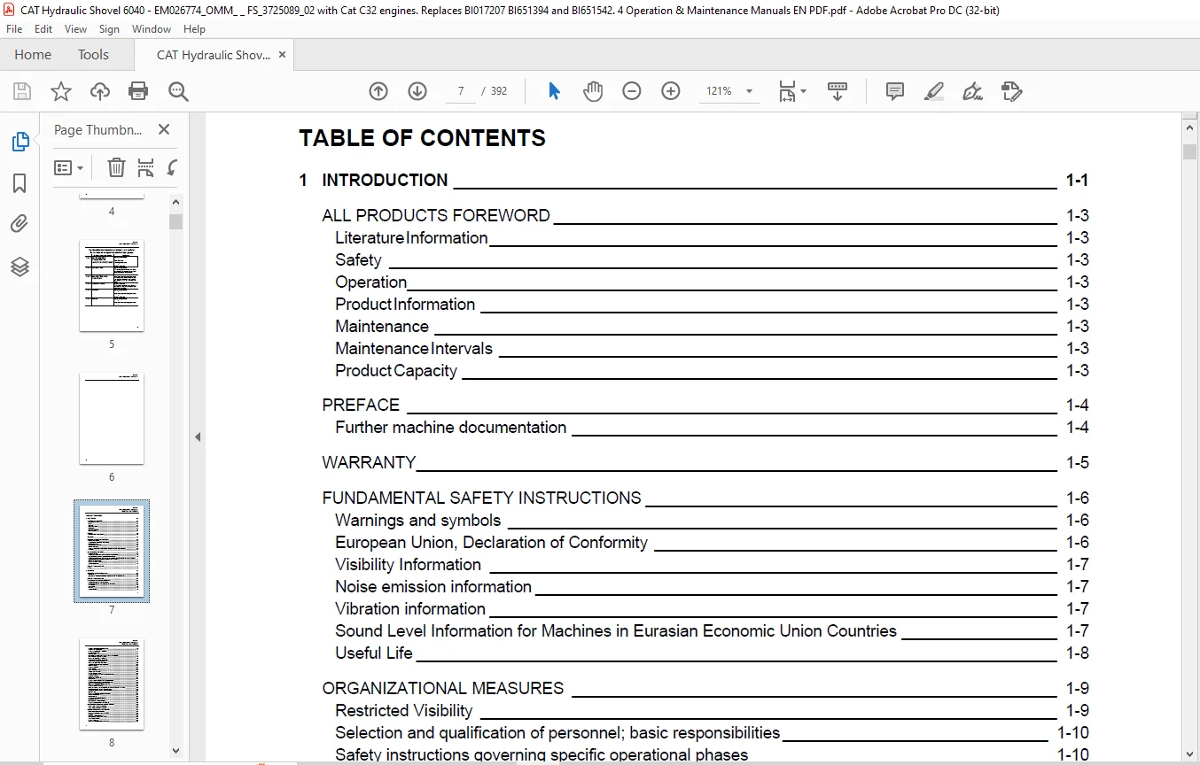
TABLE OF CONTENTS:
CAT 6040, 6040FS Hydraulic Shovel Operation & Maintenance Manual EM026774-1 – PDF DOWNLOAD
1 INTRODUCTION 1-1
ALL PRODUCTS FOREWORD 1-3
Literature Information 1-3
Safety 1-3
Operation 1-3
Product Information 1-3
Maintenance 1-3
Maintenance Intervals 1-3
Product Capacity 1-3
PREFACE 1-4
Further machine documentation 1-4
WARRANTY 1-5
FUNDAMENTAL SAFETY INSTRUCTIONS 1-6
Warnings and symbols 1-6
European Union, Declaration of Conformity 1-6
Visibility Information 1-7
Noise emission information 1-7
Vibration information 1-7
Sound Level Information for Machines in Eurasian Economic Union Countries 1-7
Useful Life 1-8
ORGANIZATIONAL MEASURES 1-9
Restricted Visibility 1-9
Selection and qualification of personnel; basic responsibilities 1-10
Safety instructions governing specific operational phases 1-10
Special work in conjunction with utilization of the machine and maintenance and repairs as well as
troubleshooting during work; disposal of parts and consumables 1-11
Warning of special dangers 1-12
Gas, dust, steam and smoke 1-12
Hydraulic equipment 1-13
FIRE AND EXPLOSION HAZARD 1-14
NOTES 1-15
2 OPERATION 2-1
OPERATION – SAFETY INSTRUCTIONS 2-3
Visibility aids 2-4
Operation and Maintenance Manuals, where to store it in the operator’s cab 2-4
FIRE AND EXPLOSION HAZARD 2-5
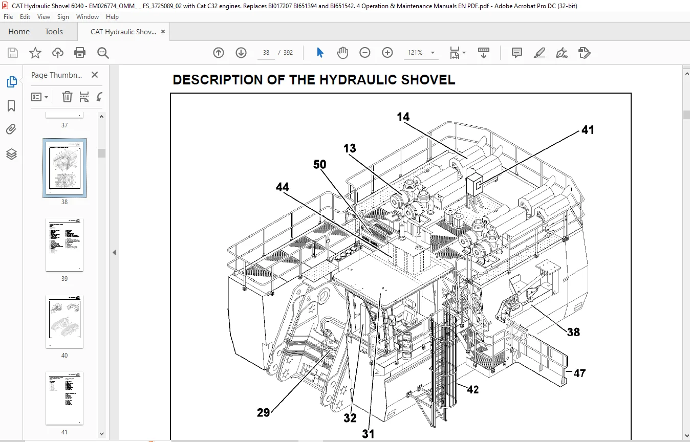
DESCRIPTION OF THE HYDRAULIC SHOVEL 2-6
Hydraulic shovel layout – upper structure 2-7
Hydraulic shovel layout – undercarriage and attachment 2-9
Undercarriage 2-10
Upper structure 2-10
Drive unit 2-10
Hydraulic system 2-10
EM026774-1
OMM 6040, 6040FS(3 725 089.03)-EN
TABLE OF CONTENTS
vi
Control and Monitoring Platform (CAMP) 2-10
Board-Control-System (BCS) 2-11
Demand control / Zero-flow regulation 2-11
Automatic reset to idling 2-11
Electrical system 2-11
Safety films and warning messages – overview and description 2-12
ISO – compliant safety messages set 2-13
Safety messages (ISO) – Description 2-18
Additional messages (ISO) – Description 2-22
ANSI – compliant safety messages set 2-27
Safety messages (ANSI) – Description 2-32
Additional messages (ANSI) – Description 2-36
Machine number 2-39
Component numbers 2-39
Engine number 2-39
Engine information decal 2-39
Eurasian Economic Union 2-40
CE-Plate, European Union 2-40
Entering and leaving the machine Safety instructions 2-41
Access ladder lighting 2-41
Swinging ladder (optional) 2-42
Folding ladder 2-43
Emergency exit in operator’s cab and escape ladder 2-44
Escape ladder near engine compartment (optional) 2-45
Switching the cab interior lighting on and off 2-46
Switching the maintenance lights on and off 2-47
Emergency shut-off function 2-48
Putting the machine back into operation, reset of emergency shut off function 2-49
Battery isolator switch, shutting off supply voltage 2-50
Starter isolator switch, shutting off starter voltage 2-50
Operator’s seat 2-51
Reducing the operators exposure to vibrations 2-53
Trainer’s / instructor’s seat 2-53
Fire extinguisher 2-54
Automatic fire-extinguishing system 2-54
Windscreen washer 2-55
Operating hours meter (if equipped) 2-55
Emergency escape device / seat (optional) 2-56
MONITORING, WARNING AND CONTROL ELEMENTS 2-60
Engine 1 (LH), control and monitoring 2-67
Engine 2 (RH), control and monitoring 2-69
PUTTING THE MACHINE INTO OPERATION 2-89
Electrical Storm Injury Prevention 2-89
Reducing the operator’s exposure to noise 2-89
Refuelling 2-90
Diesel fuel – recommendations 2-90
Back-up heating (option), filling in fuel 2-90
Service station (tanklift) 2-91
Emergency off switch 2-92
Switching the electrical system on and off 2-97
EM026774-1
OMM 6040, 6040FS(3 725 089.03)-EN
TABLE OF CONTENTS
vii
Engines, emergency shut-off 2-97
Preheating system for engine and hydraulic oil (optional) 2-98
Fuel preheating system (optional) 2-99
STARTING AND STOPPING THE ENGINES 2-100
Starting the engines 2-100
Starting the left-hand engine 2-100
Starting the right-hand engine 2-100
Engines – adjusting the speed 2-101
Starting the engines at low temperatures 2-101
Shutting off the engines 2-102
Shutting off the left-hand engine 2-102
Shutting off the right-hand engine 2-102
AIR CONDITIONER (OPTIONAL) 2-103
Back-up heating operator’s cab (optional) 2-104
Back-up heating (optional) 2-105
MAXIMUM MACHINE INCLINATIONS, INFORMATION 2-106
TRAVELING, SAFETY INSTRUCTIONS 2-108
TRAVELING 2-109
Upper structure basic position 2-109
Traveling forwards/backwards 2-109
Upper structure holding brake 2-113
Track parking brake 2-113
TRANSPORTING THE MACHINE 2-114
Transport – Safety instructions 2-114
WORKING OPERATION – SAFETY INSTRUCTIONS 2-115
WORKING OPERATION 2-117
Before starting work 2-117
Activating the electronic hydraulic shovel control (pilot control) 2-117
Swinging the upperstructure 2-118
Braking the upper structure 2-118
Working operation 2-119
After daily operation 2-120
ASSEMBLING ATTACHMENT – SAFETY INSTRUCTIONS 2-121
Securing the machine 2-122
CORROSION PROTECTION FOR PINS AND BEARINGS (BUSHINGS AND HUBS) 2-123
ON-BOARD CRANE (OPTIONAL) 2-124
On-board crane – monitoring, warning and control elements 2-124
On-board crane – putting into operation 2-125
On-board crane – drive unit 2-125
On-Board crane – blocking the boom in position of rest 2-126
On-board crane – checking 2-126
MONITORING CAMERAS (OPTIONAL) 2-127
Monitoring cameras – function 2-127
EM026774-1
OMM 6040, 6040FS(3 725 089.03)-EN
TABLE OF CONTENTS
viii
NOTES 2-128
3 INSPECTION AND SERVICING 3-1
INSPECTION AND SERVICING – SAFETY INSTRUCTIONS 3-3
INSPECTION AND SERVICING WORK, FIRE AND EXPLOSION HAZARD 3-7
INSPECTION AND SERVICING PLANS – INSTRUCTIONS 3-9
C32 Engine Maintenance Interval Schedule – Notes 3-10
Plan V 3-11
Plan N 3-13
Plan T and W 3-15
Plan A – E 3-19
LUBRICATING CHART – GREASE 3-26
Lubricating chart – Grease (legend) 3-27
Filling quantities – Grease 3-27
INSPECTION PLAN – OIL 3-28
Inspection plan – Oil (legend) 3-29
Engine oil service interval table 3-30
Engine oil service interval table with ReserveTM Oil Tank (if equipped) 3-31
Filling quantities – oil 3-32
Filling quantities – other 3-32
LUBRICANTS / CONSUMABLES 3-33
Notes on the selection of oils and greases 3-33
Avoid mixing of different hydraulic fluids 3-33
I. Oils for combustion engines 3-34
II. Fluids for hydraulic system 3-35
III.a Oils for pump drive gearboxes and travel gearboxes 3-36
III.b Oil for swing gearboxes 3-37
V. Grease for bearings, slew rings and track system (Central lubrication system) 3-38
Grease for idlers, track rollers and upper rollers (Lifetime lubrication) 3-39
Coolant for use on all combustion engines 3-40
SERVICING WORK 3-41
Hose line for oil and cooling liquid changes 3-41
ENGINE 3-42
Engine – Safety instructions 3-42
Walk-Around Inspection 3-43
Belts – Inspect/Replace 3-44
Fuel Injector – Inspect/Adjust 3-44
Engine Mounts – Inspect 3-44
Engine Oil Sample – Obtain 3-45
Engine Valve Lash – Check 3-46
Engine Valve Rotators – Inspect 3-46
Coolant Temperature Regulator – Replace 3-47
Engine Hoses and Clamps – Inspect/Replace 3-48
Engine oil – check level / top up 3-51
Engine oil reservoir (if equipped) – check oil level / top up 3-52
Engine oil – change 3-53
Engine oil reservoir (if equipped) – drain the oil off 3-55
EM026774-1
OMM 6040, 6040FS(3 725 089.03)-EN
TABLE OF CONTENTS
ix
Engine oil filter – replace 3-57
Engine oil reservoir (if equipped) – replace the oil filters 3-57
Engine crankcase breather 3-58
Engine crankcase breather – clean 3-58
Engine crankcase breathers – clean 3-58
Cold-starting fluid (ether) – Replacing the pressure vessel 3-59
COOLING SYSTEM 3-60
Temperature 3-60
Radiators 3-61
Cooling liquid level – check 3-61
Cooling liquid – change 3-64
Coolant Extender (ELC) – Add 3-66
Coolant Sample (Level 1) – Obtain 3-67
Coolant Sample (Level 2) – Obtain 3-68
Cooling System Supplemental Coolant Additive (SCA) – Test/ Add 3-69
AIR-INTAKE SYSTEM 3-71
Dust trap – clean 3-71
Main filter elements 3-72
Main filter element – check / clean 3-73
Secondary filter element – replace 3-74
Air-intake lines – inspect 3-74
FUEL SYSTEM 3-75
Fuel system – Safety instructions 3-75
Fuel filter – replace 3-75
Primary fuel filter – drain water 3-76
Primary fuel filter – replace 3-76
Fuel system – vent 3-77
Breather filter fuel tanks – replace 3-77
Fuel tanks – clean 3-77
Water trap (optional) – clean / replace 3-79
Fuel System – Prime 3-80
ELECTRICAL SYSTEM 3-81
Electrical system – Safety instructions 3-81
Alternator – Instructions 3-81
Electrical circuit diagrams 3-81
Electrical system switch-cabinets 3-81
Replacing lamps and bulbs 3-81
Battery – check the state of charge 3-82
Battery charging inside the machine – safety instructions 3-83
Battery – Removing and installing 3-84
Switchgear cabinet – aeration 3-85
Xenon floodlight projector – replacing the lamp 3-87
Lighting systems in LED technonogy – instructions 3-89
CAN-Bus wiring connections – inspect 3-90
HYDRAULIC SYSTEM 3-91
Hydraulic system – Safety instructions 3-91
Hydraulic system – depressurize 3-91
Hydraulic oil level – check 3-92
Hydraulic oil return-flow filter (hydraulic oil reservoir) – replace (up to machine no. 170129 / DHX40129)3-94
EM026774-1
OMM 6040, 6040FS(3 725 089.03)-EN
TABLE OF CONTENTS
x
Hydraulic oil return-flow filters – replace (from machine no. 170130 / DHJ40130) 3-97
Bypass valves (hydraulic oil reservoir) – clean / replace 3-99
Hydraulic oil return-flow filters (filter housing cooling system) – replace 3-100
Bypass valves (filter housing – cooling system) – clean / replace 3-101
Hydraulic oil tank breather filters – replace 3-102
Filter (control circuit and auxiliary control circuit) – check / replace 3-103
High-pressure filter for working hydraulics – check / replace 3-104
High-pressure filters for the servo circuit – check / replace 3-105
High-pressure filters for feeding circuits and slewing pumps – check / replace 3-106
Hydraulic oil – change 3-107
Avoid mixing of different hydraulic fluids 3-107
Hydraulic system – vent 3-111
Hydraulic oil cooler – Clean 3-112
Electronic hydraulic shovel control – clean / lubricate 3-113
Pressure accumulator – Emergency lowering 3-114
PUMP DRIVE GEARBOX 3-115
Pump drive gearbox oil level – check / top up with oil 3-115
Pump drive gearbox oil sample – obtain 3-116
Pre-chambers oil level – check / top up with oil 3-116
Pump drive gearbox oil – change 3-117
Pump drive gearbox pre-chambers – change the gearbox oil 3-119
Pump drive gearbox breather – replace 3-119
Pre-chamber breather – replace 3-120
Pump drive gearbox lube oil filters – replace 3-121
SWING GEARBOX 3-122
Swing gearbox oil sample – obtain 3-122
Swing gearbox oil level – check the oil level / top up with oil 3-122
Swing gearbox – vent 3-122
Swing gearbox oil – change 3-123
TRAVEL GEARBOX (PN 2763213) 3-125
Travel gearbox oil level – check / top up with oil 3-125
Pre-chamber / spur wheel section oil level – check / top up with oil 3-125
Hydraulic motor chamber oil level – check / top up with oil 3-125
Travel gearbox oil – change 3-126
Pre-chamber / spur wheel section oil – change 3-126
Hydraulic motor chamber oil -change 3-127
Travel gearbox oil sample – obtain 3-127
Travel gearbox breather filter – clean / replace 3-127
TRAVEL GEARBOX (PN 3719869) 3-128
Travel gearbox oil level – check / top up with oil 3-128
Hydraulic motor chambers oil level – check / top up with oil 3-128
Travel gearbox oil sample – obtain 3-128
Travel gearbox oil – change 3-129
Hydraulic motor chambers oil – change 3-129
CRAWLER TRACKS 3-130
Track roller fastening – check 3-130
Upper roller fastening – check 3-130
Undercarriage – check for leaks and free movement 3-130
Track roller – lubricate 3-131
EM026774-1
OMM 6040, 6040FS(3 725 089.03)-EN
TABLE OF CONTENTS
xi
Track tensioning system 3-132
Pressure-accumulator inspection regulations 3-133
Checking the gas charging pressure in the pressure accumulator 3-133
SWING RING 3-134
Swing ring – Instructions 3-134
Bearing races 3-134
Swing ring grease filling – check 3-135
Swing ring bolts – check for tightness 3-135
CENTRAL LUBRICATING SYSTEM 3-136
Central lubricating system – Design 3-136
Central lubricating system – Function 3-137
Grease container – fill up 3-138
Grease container breather filter – check / replace 3-138
Checking the greasing pressure 3-139
Grease line – unblock 3-139
Grease filter (filling the grease container) – check / replace 3-140
Grease filter (grease lines) – replace 3-141
OTHER MAINTENANCE 3-142
Engine – Clean 3-142
Travel Alarm – Test 3-142
Radiator – Clean 3-143
Aftercooler Core – Clean/Test 3-144
Air conditioning filter – clean 3-144
Attachment – check for cracks 3-145
Clam cylinder chamber – check for soiling 3-145
Window panes – clean 3-146
Mirror – check / clean / adjust 3-146
Cameras – check / clean / adjust (If equipped) 3-147
Horn – inspect / replace 3-148
Seat belt – inspect 3-149
Seat belt – replace 3-149
Hydraulic ladder, pressure accumulator 3-150
Pressure-accumulator inspection regulations 3-151
Extract from the German regulations 3-151
Checking the gas charging pressure in the pressure accumulator 3-151
ON-BOARD CRANE, DRIVE UNIT (OPTIONAL) 3-152
On-board crane – lubricate 3-152
On-Board crane – check tightness of fastening bolts 3-153
PUTTING THE HYDRAULIC SHOVEL OUT OF OPERATION AND RECOMMISSIONING 3-154
Hydraulic shovel – putting out of operation 3-154
Battery – storage 3-154
Hydraulic shovel – recommissioning 3-154
EM026774-1
OMM 6040, 6040FS(3 725 089.03)-EN
TABLE OF CONTENTS
xii
NOTES 3-156
4 REPAIR WORK 4-1
REPAIR WORK – SAFETY INSTRUCTIONS 4-3
CONFINED SPACES – SAFETY INSTRUCTIONS 4-4
REPAIR WORK – FIRE AND EXPLOSION HAZARD 4-5
REPAIR WORK – ENGINE 4-6
Overhaul Considerations 4-6
Overhaul Recommendation 4-7
HALF LIFE 4-9
FULL LIFE 4-10
Cleaning of Components 4-11
HYDRAULIC SYSTEM 4-12
Hydraulic system – repair instructions 4-12
Hydraulic hoses – Instructions 4-12
PRESSURE ACCUMULATORS – SAFETY INSTRUCTIONS 4-13
WELDING AND FLAME CUTTING WORKS – SAFETY INSTRUCTIONS 4-14
DISPOSAL AT THE END OF THE SERVICE LIFE 4-17
Appropriate disposal of batteries 4-18
NOTES 4-19
5 ANNEX 5-1
BOARD-CONTROL-SYSTEM 5-3
BCS III, what’s that? 5-3
The keys on the front side 5-4
Other elements on the front side 5-4
BCSIII – the start screen 5-5
Information given on the start screen, top section 5-6
Information given on the start screen, central section 5-7
Information given on the start screen, lower section 5-8
Emergency Stop, reset function 5-9
Swing circuit lock-out function 5-10
Information given on the “Service” screen 5-11
Engine data screen 5-12
Hydraulic data screen 5-13
Lubrication data screen 5-14
Controls adjustment data screen 5-15
View documents screen 5-16
Signal table screen 5-17
Signal table screen, location 5-18
Signal table screen, diagram 5-19
Signal table screen, diagram configuration 5-20
Code table screen 5-21
Slew brake test screen 5-22
BCS III, interfaces 5-23
EM026774-1
OMM 6040, 6040FS(3 725 089.03)-EN
TABLE OF CONTENTS
xiii
USB interface, data storage 5-23
Saving data to a USB stick 5-24
Saving data to a USB stick, continued 5-25
Saving data to a USB stick, continued 5-26
BCSIII, cleaning 5-27
BCSIII, disposal 5-27
TROUBLESHOOTING 5-28
Instructions on troubleshooting 5-28
Layout of the fault table 5-28
Possible causes 5-28
Measures 5-28
Section 5-28
FAULT TABLES 5-29
Combustion engine – Fault table 5-29
Working hydraulics – Fault table 5-30
Track drive – Fault table 5-31
Swing mechnism – Fault table 5-32
Central lubricating system – Fault table 5-33
ENGINE MONITORING, CONTROL LAMPS 5-34
HYDRAULIC CIRCUIT DIAGRAM 5-35
ABBREVIATIONS 5-36
ABBREVIATIONS 5-37
PRODUCT SPECIFICATION SHEET 5-38
NOTES 5-39
6 INDEX 6-1
Contact us: [email protected]
https://vimeo.com/857814006?share=copy
PLEASE NOTE:
- This is the same manual used by the dealers to diagnose and troubleshoot your vehicle
- You will be directed to the download page as soon as the purchase is completed. The whole payment and downloading process will take anywhere between 2-5 minutes
- Need any other service / repair / parts manual, please feel free to contact [email protected] . We still have 50,000 manuals unlisted
S.V