CAT 6090 6090FS Hydraulic Shovel Operation & Maintenance Manual – PDF DOWNLOAD
$28.95
CAT 6090 6090FS Hydraulic Shovel Operation & Maintenance Manual – PDF DOWNLOAD
Description
CAT 6090 6090FS Hydraulic Shovel Operation & Maintenance Manual – PDF DOWNLOAD
FILE DETAILS:
CAT 6090 6090FS Hydraulic Shovel Operation & Maintenance Manual – PDF DOWNLOAD
Language : English
Pages : 346
Downloadable : Yes
File Type : PDF
DESCRIPTION:
CAT 6090 6090FS Hydraulic Shovel Operation & Maintenance Manual – PDF DOWNLOAD
PREFACE:
- These operating instructions are designed to fa- miliarize the operator with the machine
and its designated use. - The operating instructions contain important in- formation on how to operate the machine
safely, properly and with maximum efficiency. Observing these instructions helps to
prevent hazardous situations, to reduce repair costs and downtimes and to increase the
reliability and service life of the machine. - The operating instructions must be supplemented by the respective national rules and regulations
for accident prevention and environmental protection. - The operating instructions must always be avail- able in the driver’s cab of the machine.
- The operating instructions must be read and put into practice by any person in charge
of carrying out work with or on the machine, such as
■ operation, including setting-up, troubleshoot- ing in the course of work, care,
evacuation of production waste and disposal of fuels and consumables,
■ maintenance (inspection, servicing, repair) and / or
■ transport.
In addition to the operating instructions and the mandatory rules and regulations for
accident pre- vention and environmental protection in the user’s country and at the place where the
machine is to be used, the generally recognized technical rules for safe and proper working must
be observed .
- The Operation and Maintenance Manual are di- rected to the mining-machine specialist. They
can- not provide basic know-how. This can be acquired, for example, in several days’ instruction by
a quali- fied CGM-HMS GmbH (Caterpillar Global Mining Hydraulic Mining Shovels GmbH)
mechanic or by attending an CGM-HMS GmbH training course for operators or maintenance
personnel. - The CGM-HMS GmbH after-sales service will be pleased to deal with any queries you may have
after reading through the Operation and Maintenance Manual. - The Operation and Maintenance Manual does not contain work instructions for carrying out
major re- pairs. Such work is willingly done for you by the
CGM-HMS GmbH after-sales service.
IMAGES PREVIEW OF THE MANUAL:
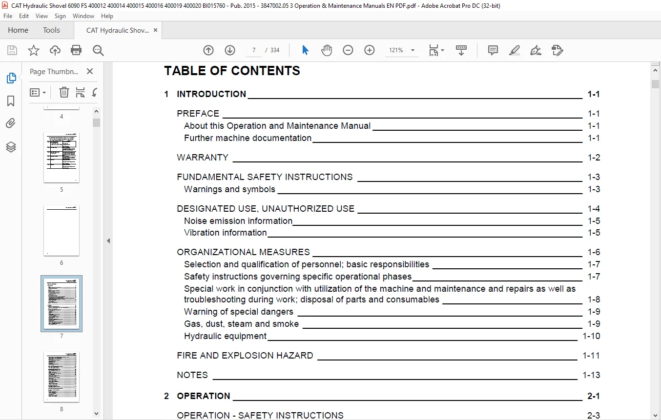
TABLE OF CONTENTS:
CAT 6090 6090FS Hydraulic Shovel Operation & Maintenance Manual – PDF DOWNLOAD
1 INTRODUCTION 1-1
PREFACE 1-1
About this Operation and Maintenance Manual 1-1
Further machine documentation 1-1
WARRANTY 1-2
FUNDAMENTAL SAFETY INSTRUCTIONS 1-3
Warnings and symbols 1-3
DESIGNATED USE, UNAUTHORIZED USE 1-4
Noise emission information 1-5
Vibration information 1-5
ORGANIZATIONAL MEASURES 1-6
Selection and qualification of personnel; basic responsibilities 1-7
Safety instructions governing specific operational phases 1-7
Special work in conjunction with utilization of the machine and maintenance and repairs as well as
troubleshooting during work; disposal of parts and consumables 1-8
Warning of special dangers 1-9
Gas, dust, steam and smoke 1-9
Hydraulic equipment 1-10
FIRE AND EXPLOSION HAZARD 1-11
NOTES 1-13
2 OPERATION 2-1
OPERATION – SAFETY INSTRUCTIONS 2-3
Operation and Maintenance Manual, where to store it in the operator’s cab 2-4
FIRE AND EXPLOSION HAZARD 2-5
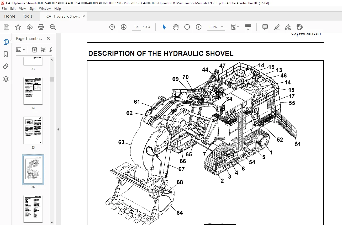
DESCRIPTION OF THE HYDRAULIC SHOVEL 2-6
Hydraulic shovel layout 2-7
Undercarriage 2-8
Upperstructure 2-8
Drive unit 2-8
Hydraulic system 2-8
Control and Monitoring Platform (CAMP) 2-8
Board-Control-System (BCS) 2-9
Demand control / Zero-flow regulation 2-9
Automatic reset to idling 2-9
Electrical system 2-9
Safety films and warning messages 2-10
Entering and leaving the machine, Safety instructions 2-18
Access ladder lighting 2-18
Folding ladder 2-19
Emergency exit in operator’s cab and escape ladder 2-20
Switching the cab interior lighting on and off 2-21
Switching the maintenance lights on and off 2-22
Emergency shut-off function 2-23
BI015760
OMM 6090, 6090FS(3 847 002.05)-EN
TABLE OF CONTENTS
vi
Putting the machine back into operation, reset of emergency shut off function 2-24
Battery isolator switch, shutting off supply voltage 2-25
Starter isolator switch, shutting off starter voltage 2-25
Operator’s seat 2-26
Reducing operators exposure to vibrations 2-28
Trainer’s / instructor’s seat 2-28
Windscreen washer 2-28
Operating hours meter 2-28
Fire extinguisher 2-29
Automatic fire-extinguishing system 2-29
Harness (optional) 2-30
MONITORING, WARNING AND CONTROL ELEMENTS 2-34
Engine 1 (LH), control and monitoring 2-41
Engine 2 (RH), control and monitoring 2-43
PUTTING THE MACHINE INTO OPERATION 2-62
Electrical Storm Injury Prevention 2-62
Reducing the operator’s exposure to noise 2-62
Refueling 2-63
Diesel fuel – recommendations 2-63
Back-up heating (option) – filling in Diesel fuel 2-63
Service station (tanklift) 2-64
Emergency off switch 2-65
Electrical system – switching on and off 2-70
Engines – emergency shut-off 2-70
STARTING AND STOPPING THE ENGINES 2-72
Engines – starting 2-72
Starting the left-hand engine 2-72
Starting the right-hand engine 2-72
Engines – adjusting the speed 2-73
Engines – starting at low temperatures 2-73
Engines – shutting off 2-74
Shutting off the left-hand engine 2-74
Shutting off the right-hand engine 2-74
AIR CONDITIONER (OPTIONAL) 2-75
Back-up heating operator’s cab (optional) 2-76
Back-up heating (optional) 2-77
MAXIMUM MACHINE INCLINATIONS, INFORMATION 2-78
TRAVELING – SAFETY INSTRUCTIONS 2-80
TRAVELING 2-81
Upperstructure basic position 2-81
Traveling forwards/backwards 2-81
Upperstructure holding brake 2-85
Track parking brake 2-85
TRANSPORTING THE MACHINE 2-86
Transport – Safety instructions 2-86
BI015760
OMM 6090, 6090FS(3 847 002.05)-EN
TABLE OF CONTENTS
vii
WORKING OPERATION – SAFETY INSTRUCTIONS 2-87
WORKING OPERATION 2-89
Before starting work 2-89
Activating the electronic shovel control 2-89
Swinging the upperstructure 2-90
Braking the upperstructure 2-90
Working operations 2-91
Emergency lowering of the equipment 2-92
After daily operation 2-93
ASSEMBLING WORKING EQUIPMENT – SAFETY INSTRUCTIONS 2-94
Safety line on boom 2-94
Main control valves – attach/remove the handrail 2-95
Securing the machine 2-95
CORROSION PROTECTION FOR PINS AND BEARINGS (BUSHINGS AND HUBS) 2-96
ON-BOARD CRANE (OPTIONAL) 2-97
On-board crane – monitoring, warning and control elements 2-97
On-board crane – putting into operation 2-98
On-board crane – drive unit 2-98
On-Board crane – blocking the boom in position of rest 2-99
On-board crane – checking 2-99
Monitoring cameras 2-100
NOTES 2-1
3 INSPECTION AND SERVICING 3-1
INSPECTION AND SERVICING – SAFETY INSTRUCTIONS 3-3
INSPECTION AND SERVICING WORK, FIRE AND EXPLOSION HAZARD 3-7
INSPECTION AND SERVICING PLANS – INSTRUCTIONS 3-9
Plan V 3-11
Plan N 3-13
Plan T and W 3-15
Plan T and W 3-16
Plan A – E 3-17
LUBRICATING CHART 3-24
Lubricating chart – Grease (legend) 3-25
Filling quantities – Grease 3-25
INSPECTION PLAN – OIL 3-26
Inspection plan – Oil (legend) 3-27
Filling quantities – oil 3-28
Filling quantities – other 3-28
LUBRICANTS / CONSUMABLES 3-29
Notes on the selection of oils and greases 3-29
Avoid mixing of different hydraulic fluids 3-29
I. Oil for combustion engines and compressors 3-30
II. Fluid for hydraulic system 3-31
III.a Oil for pump drive gearboxes and travel gearboxes 3-32
BI015760
OMM 6090, 6090FS(3 847 002.05)-EN
TABLE OF CONTENTS
viii
III.b Oils for swing gearboxes 3-33
V. Greases for bearings, swing rings and track system 3-34
Coolant for use on all combustion engines 3-35
SERVICING WORK 3-36
Hose line for oil and cooling liquid changes 3-36
ENGINE 3-37
Engine – Safety instructions 3-37
Engine oil – checking the oil level / topping up 3-38
Engine oil reservoir – checking the oil level 3-39
Engine oil – change 3-40
Engine oil reservoir – filling in / draining off the oil 3-42
Eliminator filter and centrifuge 3-45
Cold-starting fluid (ether) – Replacing the pressure vessel 3-47
COOLING SYSTEM 3-48
Radiators 3-49
Cooling-liquid level, check 3-49
Cooling-liquid, topping up 3-50
Cooling liquid change 3-52
Water filter, change 3-54
AIR-INTAKE SYSTEM 3-55
Main filter elements 3-55
Secondary filter element 3-58
Air-intake lines, check 3-59
Dust collection, function 3-59
FUEL SYSTEM 3-60
Fuel system – Safety instructions 3-60
Fuel tank supply valve, function 3-60
Fuel filters, replace 3-60
Fuel filters, draining water 3-62
Fuel tank breather filter, replace 3-63
Fuel tanks, clean 3-63
ELECTRICAL SYSTEM 3-65
Electrical system – Safety instructions 3-65
Alternator – Instructions 3-65
Electrical circuit diagrams 3-65
Electrical system switch-cabinets 3-65
Replacing lamps and bulbs 3-65
Xenon floodlight projector, replacing the lamp 3-66
Lighting systems in LED technology, instructions 3-68
Battery, checking the state of charge 3-69
Battery, removing and installing 3-70
Charging batteries inside the machine, safety instructions 3-71
Switchgear cabinet filters 3-72
HYDRAULIC SYSTEM 3-74
Hydraulic system – Safety instructions 3-74
Hydraulic system, depressurizing 3-74
Hydraulic oil level, check 3-75
BI015760
OMM 6090, 6090FS(3 847 002.05)-EN
TABLE OF CONTENTS
ix
Hydraulic oil return-flow filters (hydraulic oil reservoir), replace 3-77
Bypass valves (hydraulic oil reservoir) 3-79
Hydraulic oil return-flow filters (filter housing cooling system), replace 3-80
Bypass valves (filter housing – cooling system) 3-81
Hydraulic tank breather filter, replace 3-82
Filter (control circuit main pumps), replace 3-83
High-pressure filter for working hydraulics, replace 3-84
High-pressure filters for the servo circuit, replace 3-85
High-pressure filters for pump-flushing circuit 3-86
High-pressure filters for feeding circuits and swing pumps 3-87
High-pressure filters for swing circuit, replace 3-88
Changing the hydraulic oil 3-89
Avoid mixing of different hydraulic fluids 3-89
Venting the hydraulic system 3-92
Cleaning the hydraulic oil cooler 3-93
Electronic shovel control 3-94
Pressure accumulator – Emergency lowering 3-95
PUMP DRIVE GEARBOX 3-96
Pump drive gearbox – checking the oil level / topping up with oil 3-96
Pump drive gearbox – changing the gearbox oil 3-97
Pump drive gearbox – breather 3-98
Pump drive gearbox – pre-chambers expansion reservoir 3-98
Pump drive gearbox lube oil filters – clean / replace 3-99
SWING GEARBOX 3-100
Swing gearbox – checking the oil level / topping up with oil 3-100
Swing gearbox venting 3-100
Swing gearbox – changing the gearbox oil 3-101
TRAVEL GEARBOX 3-103
Travel gearbox – checking the oil level / topping up with oil 3-103
Travel gearbox – changing the oil 3-103
CRAWLER TRACKS 3-105
Tracks – cleaning 3-105
Carbody-crawler frame fastening bolts and disks – replace 3-105
Track tensioner 3-106
Pressure-accumulator inspection regulations 3-108
Checking the gas charging pressure in the pressure accumulator 3-108
SWING RING 3-109
Swing ring – Instructions 3-109
Bearing races 3-109
CENTRAL LUBRICATING SYSTEM 3-111
Design 3-111
Function 3-112
Filling up the grease container 3-113
Breather filter 3-113
Checking the greasing pressure 3-114
Unblocking a grease line 3-114
Oil filter for hydraulic circuit grease pump – replace 3-115
Grease filter replace (Filling the grease container) 3-116
BI015760
OMM 6090, 6090FS(3 847 002.05)-EN
TABLE OF CONTENTS
x
Grease filter replace (Grease lines) 3-117
OTHER MAINTENANCE 3-118
Engine 3-118
Reservoirs for used grease at the A-frame – emptying 3-119
Heating and air conditioning, check 3-119
Working equipment – check welding seems 3-120
Clam cylinder chamber – check for soiling 3-120
Window panes – cleaning 3-121
Mirror – cleaning / adjusting position 3-121
HYDRAULIC LADDERS (OPTIONAL) 3-122
Pressure-accumulator inspection regulations 3-123
Extract from the German regulations 3-123
Checking the gas charging pressure in the pressure accumulator 3-123
ON-BOARD CRANE, DRIVE UNIT 3-124
On-board crane, lubricating 3-125
On-Board crane, checking tightness of fastening bolts 3-125
PUTTING THE HYDRAULIC SHOVEL OUT OF OPERATION AND RECOMMISSIONING 3-126
Putting the hydraulic shovel out of operation 3-126
Battery storage 3-126
Recommissioning 3-126
NOTES 3-127
4 REPAIR WORK 4-1
REPAIR WORK – SAFETY INSTRUCTIONS 4-3
CONFINED SPACES – SAFETY INSTRUCTIONS 4-4
REPAIR WORK – FIRE AND EXPLOSION HAZARD 4-5
REPAIR WORK – ENGINE 4-6
HYDRAULIC SYSTEM 4-7
Repair instructions 4-7
Hydraulic hoses – Instructions 4-7
PRESSURE ACCUMULATORS – SAFETY INSTRUCTIONS 4-8
WELDING AND FLAME CUTTING WORKS – SAFETY INSTRUCTIONS 4-9
DISPOSAL AT THE END OF THE SERVICE LIFE 4-12
Dismantling and removal instructions 4-12
Risk of deflagrations 4-12
Risk of fire 4-12
Disposing of the machine without polluting the environment 4-13
Further hazardous substances 4-13
Appropriate disposal of batteries 4-14
BI015760
OMM 6090, 6090FS(3 847 002.05)-EN
TABLE OF CONTENTS
xi
NOTES 4-15
5 ANNEX 5-1
BOARD-CONTROL-SYSTEM, OPERATOR LEVEL 5-3
BCS III, what’s that? 5-3
The keys on the front side 5-4
Other elements on the front side 5-4
BCSIII, the start screen 5-5
Information given on the start screen, top section 5-6
Information given on the start screen, central section 5-7
Information given on the start screen, lower section 5-8
Emergency Stop, reset function 5-9
Swing circuit lock-out function 5-10
Information given on the “Service” screen 5-11
Engine data screen 5-12
Hydraulic data screen 5-13
Lubrication data screen 5-14
Controls adjustment data screen 5-15
View documents screen 5-16
Signal table screen 5-17
Signal table screen, location 5-18
Signal table screen, diagram 5-19
Signal table screen, diagram configuration 5-20
Code table screen 5-21
Slew brake test screen 5-22
BCS III, interfaces 5-23
USB interface, data storage 5-23
Saving data to a USB stick 5-24
Saving data to a USB stick, continued 5-25
Saving data to a USB stick, continued 5-26
BCSIII, cleaning 5-27
BCSIII, disposal 5-27
TROUBLESHOOTING 5-28
Instructions on troubleshooting 5-28
Layout of the fault table 5-28
Possible causes 5-28
Measures 5-28
Section 5-28
FAULT TABLES 5-29
Combustion engine – Fault table 5-29
Working hydraulics – Fault table 5-30
Track drive – Fault table 5-31
Swing mechanism – Fault table 5-32
Central lubricating system – Fault table 5-33
Engine control module, displaying stored fault codes 5-34
HYDRAULIC CIRCUIT DIAGRAM 5-36
Vibration data 5-36
BI015760
OMM 6090, 6090FS(3 847 002.05)-EN
TABLE OF CONTENTS
xii
ABBREVIATIONS 5-37
ABBREVIATIONS 5-38
PRODUCT SPECIFICATION SHEET 5-39
NOTES 5-41
6 INDEX 6-1
Contact us: [email protected]
https://vimeo.com/857139895?share=copy
PLEASE NOTE:
- This is not a physical manual but a digital manual – meaning no physical copy will be couriered to you. The manual can be yours in the next 2 mins as once you make the payment, you will be directed to the download page IMMEDIATELY.
- This is the same manual used by the dealers inorder to diagnose your vehicle of its faults.
- Require some other service manual or have any queries: please WRITE to us at [email protected]
S.V