Cat Bucyrus 25M Series CONTINUOUS MINER Operation Manual – PDF DOWNLOAD
$28.95
Cat Bucyrus 25M Series CONTINUOUS MINER Operation Manual – PDF DOWNLOAD
Description
Cat Bucyrus 25M Series CONTINUOUS MINER Operation Manual – PDF DOWNLOAD
FILE DETAILS:
Cat Bucyrus 25M Series CONTINUOUS MINER Operation Manual – PDF DOWNLOAD
Language :English
Pages :251
Downloadable : Yes
File Type : PDF
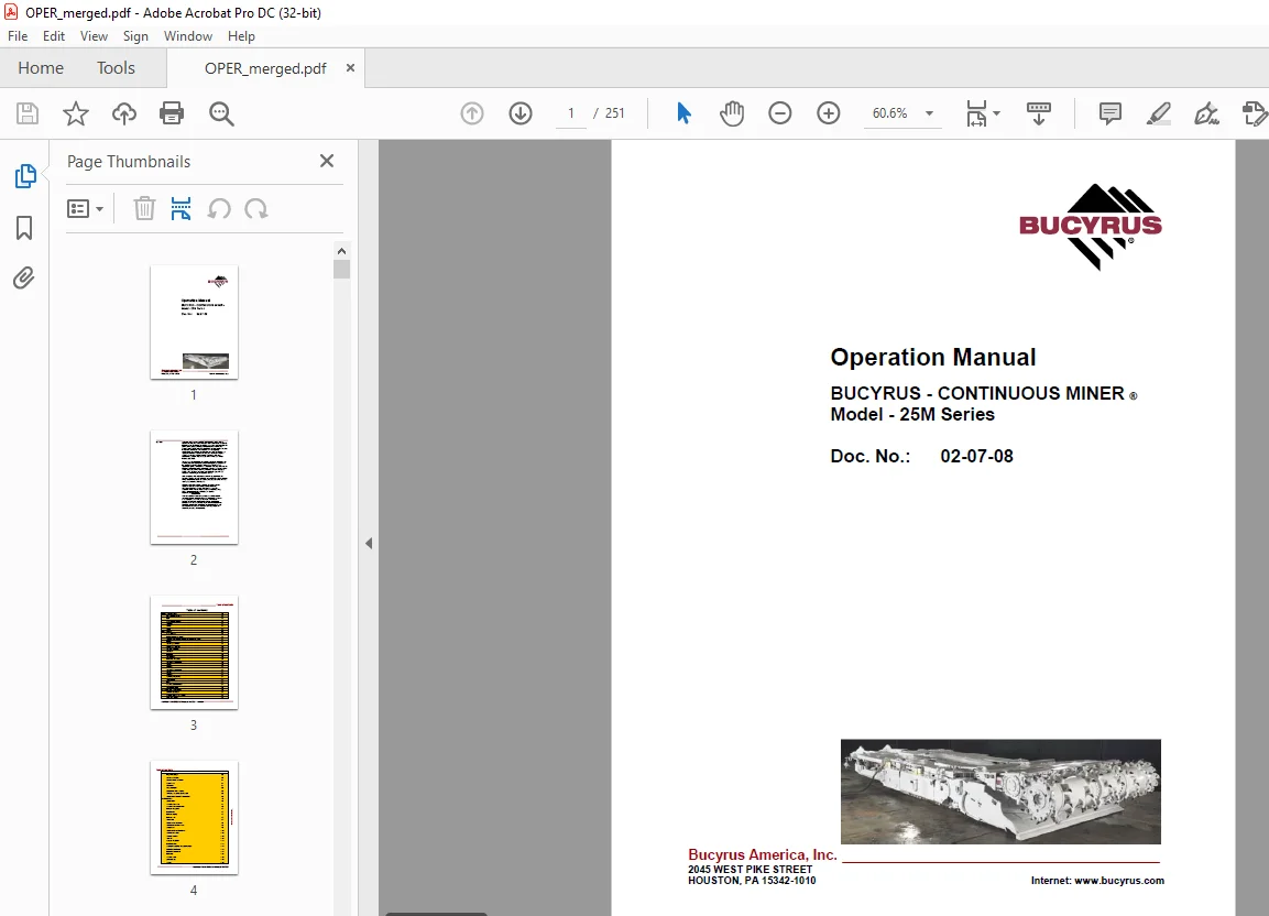
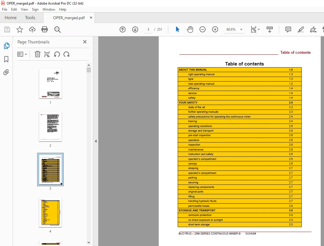
IMAGES PREVIEW OF THE MANUAL:
DESCRIPTION:
Cat Bucyrus 25M Series CONTINUOUS MINER Operation Manual – PDF DOWNLOAD
preface
- This manual is intended to provide basic operating information on Bucyrus America, Inc. 25M Series class continuous miners. Additional information can be obtained by referring to the Parts Book supplied with your machine, or by contacting your local Bucyrus America, Inc. representative. The illustrations, descriptions and procedures contained in this manual pertained to the machine as it was originally manufactured and delivered to your mine, and when the manual was approved for printing. Bucyrus America, Inc.
- reserves the right to discontinue or revise machine models at any time, or change specifications, designs or procedures, without notice and without incurring obligations. The machine was manufactured under the guidelines, procedures and requirements of the appropriate government regulatory agencies. At the completion of manufacturing, this machine was issued the appropriate approval numbers and nameplates indicating that it met the technical requirements of the appropriate agencies.
- Any change to the design or structure of this machine, without the consent of Bucyrus America, Inc. and these agencies, may void these approvals and render the machine illegal or dangerous for use. Strict compliance with all local and national laws, regulations and practices regarding the safe operation and maintenance of underground mining equipment is necessary to ensure the personal safety of those working on, or around, this machine. While this manual attempts to anticipate the most important operations and maintenance needs for this equipment, unforeseen circumstances may arise that have not been addressed in this manual. If any concerns or questions arise, please contact your Bucyrus America, Inc. Service Representative immediately.
- This work contains information protected under trade secret and other intellectual property laws, and is protected under the U. S. Copyright Act of 1976, as amended. This work is provided under license and the license is non-transferable. Distribution and access is limited only to authorized personnel. Disclosure, reproduction, distribution or unauthorized use may be a violation of federal and state laws and may subject the unauthorized user to criminal liability
TABLE OF CONTENTS:
Cat Bucyrus 25M Series CONTINUOUS MINER Operation Manual – PDF DOWNLOAD
ABOUT THIS MANUAL 1.0
right operating manual 1.3
type 1.3
new operating manual 1.3
efficiency 1.4
service 1.4
safety 1.4
YOUR SAFETY 2.0
state of the art 2.3
further operating manuals 2.3
safety precautions for operating the continuous miner 2.4
training 2.4
operating conditions 2.5
storage and transport 2.6
pre-start inspection 2.6
operation 2.6
inspection 2.6
maintenance 2.6
instruction and safety 2.6
operator’s compartment 2.6
canopy 2.6
stopping 2.7
operator’s compartment 2.7
parking 2.7
securing 2.7
replacing components 2.7
original parts 2.7
lifting 2.7
handling hydraulic fluids 2.7
permissible hoses 2.8
STORAGE AND TRANSPORT 3.0
corrosion protection 3.3
no direct exposure to sunlight 3.3
short term storage 3.3
BUCYRUS – DASH SERIES CONTINUOUS MINER ©
© BUCYRUS AMERICA, INC.
long term storage 3.3
plastic deformation 3.3
random sample inspection 3.4
natural aging 3.4
HFA fluids 3.4
before transport 3.5
temperature below freezing 3.5
electrical and electronic components 3.5
INSTALLATION 4.0
special tools 4.3
general safety rules 4.4
general safety maintenance 4.5
lubricate every shift 4.7
inspect daily 4.7
lubricate weekly 4.7
lubricate daily 4.7
check daily 4.7
replace when necessary 4.8
electric motor maintenance 4.8
every month 4.8
electrical motor maintenance 4.10
every three months 4.10
every six months 4.10
annually 4.10
notes on installation 4.11
installation plan 4.11
superbolt installation and specifications 4.12
tightening procedures 4.12
loosening procedures 4.13
lubricants 4.14
safety features 4.16
panic strip (s) 4.16
canopy 4.16
antifreeze measures for oil cooler 3.5
Guards and covers 4.16
Circuit breaker reset 4.16
OPERATION 5.0
Cutter head assembly 5.3
Boom pivot pin 5.4
Drum drive torque limiting switch 5.5
Drum drive motor—dash-0 & dash-1 5.5
Drum drive motor—dash-2 & dash-3 5.6
Shear cylinder—dash-0, dash-1 & dash-2 5.7
Shear cylinder—dash-3 5.8
Cutter drums—dash-0 5.8
Center cutter drums 5.8
End cutter drums 5.9
Main cutter drums 5.9
Cutter drums installation / removal—dash-1 5.10
Center cutter drum 5.10
End cutter drum 5.11
Main cuter drum 5.11
Cutter drums installation / removal—dash-2 5.12
End cutter drums 5.13
Center cutter drum 5.14
End cutter drum 5.14
Gear case installation / removal—dash-0 5.15
Gear case installation / removal—dash-1 5.16
Gear case installation / removal—dash-2 & 3—see figures 21 & 22 5.17
Figure 21 5.18
Figure 22 5.19
Cutter boom gear case—dash-2 & 3 5.20
Gathering head assembly installation / removal—see figure 14 & 15 5.21
CLA installation / removal—see figure 16 5.22
Gathering head motor installation / removal 5.23
Foot shaft installation / removal 5.23
Gear case installation / removal 5.24
Lift cylinder installation / removal—see figure 23 5.25
Tractor frame assembly—see figure 1 5.26
Tram primary planetary gear installation / removal—see figure 3 5.27
Table of contents ___________________________________________
tram secondary planetary gear installation / removal—see figure-4 5.28
tram case installation / removal 5.29
stabilizing cylinder installation / removal—see figure-7 5.30
tram sprocket assembly installation / removal—see figure-8 5.31
tram track adjustment—see figure-9 5.32
tram track front idler installation / removal—see figure-10 5.34
front idler take-up jack assembly 5.35
hydraulic pump installation / removal—see figure 12 5.35
hydraulic pump motor installation / removal—see figure 13 5.36
conveyor assembly installation / removal—see figure 38 & 39 5.37
swing cylinder installation / removal—see figure-40 5.38
swivel pin installation / removal—see figure-41 5.39
tail roller installation / removal—see figure-42 5.40
tail shim adjustment—see figure-43 5.40
lift cylinder installation / removal—see figure-44 5.41
chain installation / removal—see figure-45 5.42
chain tension adjustment—see figure-46 5.42
scrubber system—see figure-47 5.44
scrubber cleaning—see figure-48 5.45
fan motor assembly—see figure-49 5.45
power schematic—see figures 50, 51, 52, 56, 57 & 58 5.46
motor overloads 5.46
motor control 5.47
motor contactors—see figure-67 5.47
cutter motor feedback 5.47
radio control schematic—see figure-53 5.48
tram dead man—see figure-54 5.48
methane monitor 5.49
low oil level 5.49
e-stop bypass—see figure-55 5.49
battery back-up 5.49
scrubber fan 5.49
cutter motor feedback adjustment—see figure-59 5.50
armature voltage—see figures 60 & 61 5.51
transmitter—see figures 64 & 65 5.53
battery charger 5.53
permissibility 5.53
troubleshooting 5.54
dual systems 5.54
diagnostic display 5.55
component change out 5.55
TECHNICAL DATA 6.0
tractor frame assemblies—figure-1 6.4
tractor frame-tractor motor—figure-2 6.5
tram preliminary planetary gear—figure-3 6.6
tram secondary planetary gear—figure-4 6.7
tram case—figure-5 6.8
tram case—figure-6 6.9
stabilizing cylinder—figure-7 6.10
tram sprocket—figure-8 6.11
tram track adjustment—figure-9 6.12
tram track front idler—figure-10 6.13
front idler take-up jack—figure-11 6.14
hydraulic pump—figure-12 6.15
hydraulic pump motor—figure-13 6.16
gathering head—figure-14 6.17
gathering head assembly—figure-15 6.18
gathering head CLA installation / removal—figure-16 6.19
gathering head motor installation / removal—figure-17 6.20
gathering head foot shaft installation / removal—figure-18 6.21
foot shaft assembly—figure-19 6.22
gathering head gear case installation / removal—figure-20 6.23
gathering head gear case assembly—figure-21 6.24
gathering head gear case assembly—figure-22 6.25
gathering head lift cylinder installation / removal—figure-23 6.26
cutter head assemblies—figure-24 6.27
cutter head book assemblies—figure-25 6.28
radio remote control—see figures 62, 70 & 71 5.52
receiver, power supply and module traction case—see figure-69 5.52
diagnostic display—see figure-63 5.53
© BUCYRUS AMERICA, INC.
cutter head—dash 0, 1 & 2 boom pivot pin—figure-26 6.29
cutter head—dash-3 boom pivot pin—figure-27 6.30
cutter head dash 2 & 3 drum drive torque limiting clutch—figure-28 6.31
cutter head dash 2 & 3 drum drive motor—figure-29 6.32
cutter head—dash 0 & 1 drum drive motor—figure-30 6.33
cutter head—dash 0, 1 & 2—figure-32 6.34
cutter head—dash 3 shear cylinder—figure-33 6.35
cutter boom—dash 0 cutter drums—figure-34 6.36
cutter boom—dash 1 cutter drums 6.37
cutter boom—dash 2 cutter drums—figure-36 6.38
cutter doom—dash 3 drums—figure-37 6.39
conveyor—figure-38 6.40
conveyor—figure-39 6.41
swing cylinder—figure-40 6.42
swivel pin—figure-41 6.43
tail roller—figure-42 6.44
tail shim—figure-43 6.45
FOR YOUR INFORMATION 7.0
our service 7.3
service addresses 7.3
S.M 25/3/2025