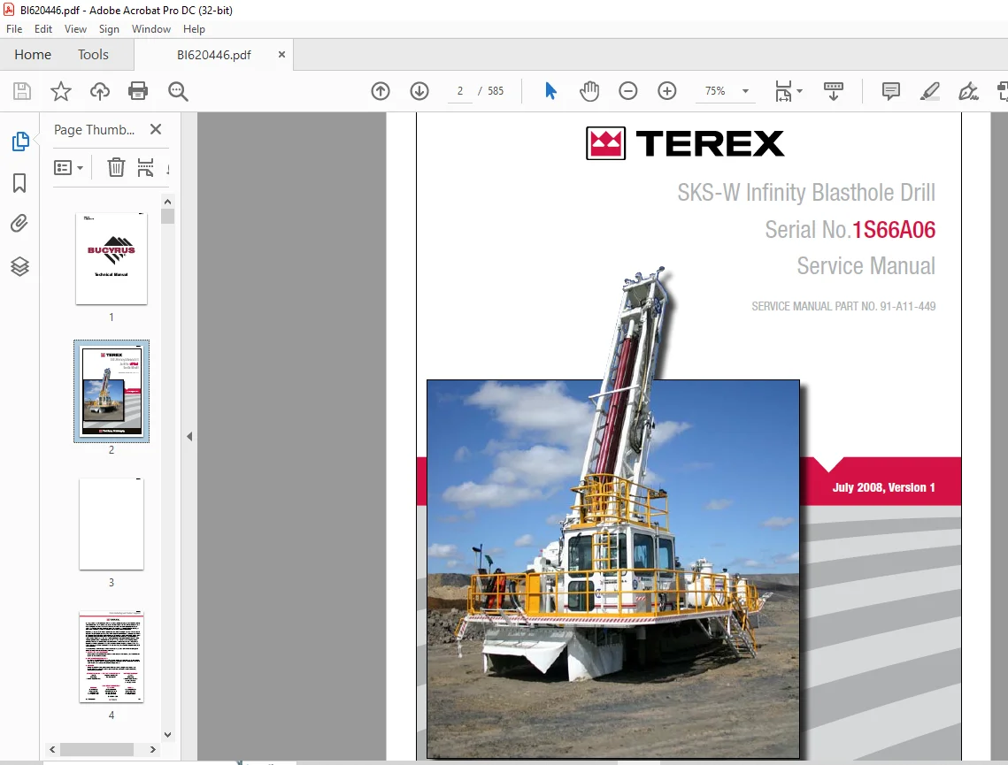
Cat Bucyrus 345 Hydra-Trac® Hydraulic Track Drill Service Manual PN 419395 – PDF DOWNLOAD
$30.95
Cat Bucyrus 345 Hydra-Trac® Hydraulic Track Drill Service Manual PN 419395 – PDF DOWNLOAD
Description
Cat Bucyrus 345 Hydra-Trac® Hydraulic Track Drill Service Manual PN 419395 – PDF DOWNLOAD
FILE DETAILS:
Cat Bucyrus 345 Hydra-Trac® Hydraulic Track Drill Service Manual PN 419395 – PDF DOWNLOAD
Language : English
Pages : 585
Downloadable : Yes
File Type : PDF
IMAGES PREVIEW OF THE MANUAL:
DESCRIPTION:
Cat Bucyrus 345 Hydra-Trac® Hydraulic Track Drill Service Manual PN 419395 – PDF DOWNLOAD
Before Operation:
• Do notify the owner of overhead or underground power lines before drilling. Be sure to comply
with all local regulations regarding safe operating distances from power lines. See table 1-1 for
general guidelines for safe distances from high voltage lines.
• Do study this manual and fully understand the controls.
• Do be sure all safety guards are securely in place.
• Do wear safety helmet, glasses and hearing protection when operating or working on machine.
• Do be sure all personnel are clear of the machine and work area before starting the engine or
operating machine.
• Do be sure drill area is clear of all obstructions before operating machine.
• Do attach safety chain when using towbar.
• Do Not operate machine with:
• Hydraulic or air leaks
• Broken or damaged electrical wiring or components
• Damaged hydraulic hoses or fittings
Operation:
• Do examine the surface before drilling to determine the possible presence of unfired
explosives.
• Do provide sufficient ventilation when running the engine in an enclosed area. Exhaust gasses
contain carbon monoxide, a deadly poison, which is colorless and odorless.
• Do keep work areas clean and clear of cuttings, hand tools and other objects.
• Do place feed in horizontal position with feed resting on feed rest (if equipped) when
tramming over rough ground or during long moves. When moving from hole to hole, be sure feed is
high enough to clear ground obstacles. If feed hits something while tramming, feed can fall causing
serious injury or death.
• Do Not use the machine for any other purpose than what it was designed for. This machine is
designed for blasthole drilling operations only.
• Do Not wear jewelry or loose fitting clothing when working on machinery. Keep clothing and
hands clear of moving parts.
• Do Not travel on steep inclines, soft or unstable ground or close to unsupported excavations.
• Do Not move boom or machine if it is in a potentially unstable position.
• Do Not stand directly under a boom or feed.
• Do Not drill into or near a “bootleg” hole or any hole that may contain explosives.
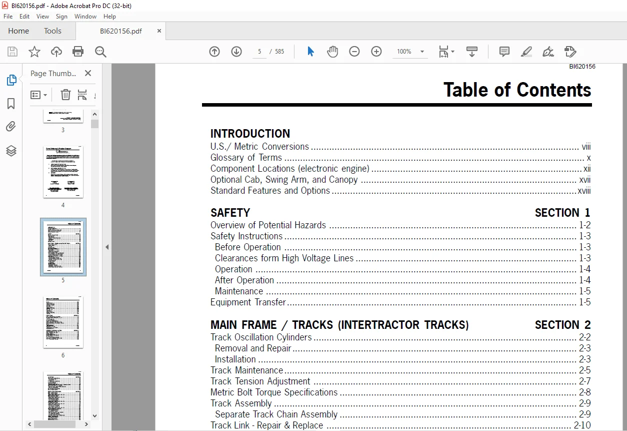
TABLE OF CONTENTS:
Cat Bucyrus 345 Hydra-Trac® Hydraulic Track Drill Service Manual PN 419395 – PDF DOWNLOAD
INTRODUCTION
U S / Metric Conversions viii
Glossary of Terms x
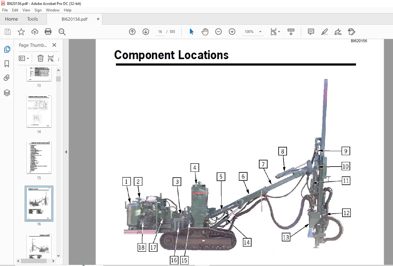
Component Locations (electronic engine) xii
Optional Cab, Swing Arm, and Canopy xvii
Standard Features and Options xviii
SAFETY SECTION 1
Overview of Potential Hazards 1-2
Safety Instructions 1-3
Before Operation 1-3
Clearances form High Voltage Lines 1-3
Operation 1-4
After Operation 1-4
Maintenance 1-5
Equipment Transfer 1-5
MAIN FRAME / TRACKS (INTERTRACTOR TRACKS) SECTION 2
Track Oscillation Cylinders 2-2
Removal and Repair 2-3
Installation 2-3
Track Maintenance 2-5
Track Tension Adjustment 2-7
Metric Bolt Torque Specifications 2-8
Track Assembly 2-9
Separate Track Chain Assembly 2-9
Track Link – Repair & Replace 2-10
Track Shoe (grouser) – Mounting to Track Chain 2-12
Grouser Bolt Torque (Direct Torque Method) 2-14
Grouser Bolt Torque (Torque Turn Method) 2-15
Track Chain & Shoe – Assembly & Installation 2-16
Crawler Carriage 2-18
Final Drive – General Description 2-18
Final Drive – Removal from Track Frame 2-19
Final Drive – Installation into Track Frame 2-20
Final Drive Maintenance 2-21
Oil Check/Change 2-21
Oil Specifications 2-22
Recommended Oils 2-22
Final Drive Assembly 2-24
Parking Brake – Description 2-25
Parking Brake – Removal & Installation 2-27
Towing Procedure – Gear Drive Disconnect 2-27
BI620156
iv Introduction
Table of Contents
Idler Unit 2-28
General Description 2-28
Removal & Disassembly 2-30
Assembly & Installation 2-32
Track Rollers 2-35
General Description 2-35
Removal & Disassembly 2-36
Assembly 2-38
Test & Installation 2-39
Support Rollers 2-40
General Description 2-40
Removal & Disassembly 2-41
Assembly 2-43
POWER TRAIN SECTION 3
Hydraulic Pumps – Removal and Installation 3-3
Fuel System – Caterpillar C-9 (electronic engine) 3-4
Fuel Tank 3-4
Fuel Filter – Installation 3-5
Fuel System – Maintenance 3-6
Change Oil & Filter – Every 250 Hours 3-8
Caterpillar C-9 Engine Oil Grade Detection Plugs 3-9
Engine Radiator (Caterpillar C-9) – Capacity and Service 3-10
Coolers 3-11
Coolant Specifications 3-11
Cooler Maintenance 3-11
Radiator/Oil Cooler Service 3-12
Coolers – Removal and Installation 3-13
Changing Hydraulic Oil 3-15
HYDRAULIC/ELECTRICAL SYSTEMS SECTION 4
Tram Valve Components and Valve Tray 4-2
Hydraulic Piping (electronic engine) 4-5
Boom and Feed Piping 4-6
Dual Boom Control Piping 4-7
Boom and Feed Piping with Swing Arm 4-8
Drill Control Circuit 4-10
Electrical Schematic (electronic engine) 4-13
Tram Control Circuit from Drill Console at Feed 4-14
Electrical Schematic (Cab Machines) 4-15
BI620156
Introduction v
Table of Contents
AIR SYSTEM SECTION 5
Compressor Oil Separator Element: 5-2
Preventive Maintenance 5-2
Air Receiver Tank 5-3
Air Receiver Tank – Troubleshooting 5-4
Air System Components 5-7
Compressor Oil Piping 5-9
Thermostatic Bypass Valve 5-9
Compressor Assembly – 300 CFM with Variable Displacement Motor 5-10
Compressor Unit – Removal and Installation 5-11
Drive Coupling – Replacement of Rubber Drive Blocks 5-11
Drive Coupling – Replacement 5-13
Drill String Grease System (optional) 5-14
Detergent System (optional) 5-16
BOOM & FEED COMPONENTS SECTION 6
Boom Lift Cylinder – Removal 6-2
Boom Lift Cylinder – Replace 6-3
Cylinder Bleeding Procedure and final installation: 6-3
Boom Swing Cylinder – Removal 6-4
Boom Swing Cylinder – Replace 6-4
Cylinder Bleeding Procedure and final installation: 6-5
Feed Dump Cylinder – HD Boom 6-6
Feed Dump Cylinder – Removal 6-6
Feed Dump Cylinder – Replace 6-7
Cylinder Bleeding Procedure and final installation: 6-7
Feed Swing Cylinder – Removal 6-8
Feed Swing Cylinder – Replace 6-9
Cylinder Bleeding Procedure and final installation: 6-9
Feed Extension Cylinder – HD Boom 6-10
Feed Extension Cylinder – Removal 6-10
Feed Extension Cylinder – Replace 6-11
Cylinder Bleeding Procedure and final installation: 6-11
HD Boom Shim/Wear Pad Replacement 6-12
Heavy Duty Boom – Inspection 6-13
Feed and Feed Table – Removal 6-14
Inner Boom Tube – Removal 6-17
Boom Tube, Wear Pads & Shims – Installation 6-19
Feed and Feed Table – Installation 6-20
Feed Table Wear Pads – Adjustment 6-22
Feed Table Pivot Pin Adjustment and Maintenance 6-23
HPR45/51 Hydraulic Rock Drill 6-24
Removal from Mounting Slide 6-24
Installation on Mounting Slide 6-42
Mounting Slide Adjustment 6-25
HPR1H-ATW Hydraulic Rock Drill 6-26
BI620156
vi Introduction
Table of Contents
Removal from Mounting Slide 6-27
Installation on Mounting Slide 6-27
Feed Chain Adjustment 6-29
PRESSURE SETTINGS & ADJUSTMENTS SECTION 7
Engine Adjustments 7-2
Caterpillar C-9 Electronic Engine – ECM Diagnostic Light 7-3
Brake Valve Adjustments 7-4
Tram Valve Adjustments (manual) 7-7
Tram Valve/Joystick Adjustments (electric) 7-8
Boom Joystick Adjustment 7-10
Main Pump Adjustments (Oilgear) 7-15
Rotation Pump Adjustments (Oilgear) 7-17
Drill Valve Adjustments 7-19
Drill (Hammer), Rotation, Feed & Feed Override Valves 7-19
Compressor Speed & Motor Adjustment 7-20
Drive Coupling – Repair & Replacement 7-22
Dust Collector Assembly (optional) 7-25
Function of Dust Collector 7-25
Initial Start-up and Tuning 7-26
To Set Dust Collector Valve 7-26
To Set Timer 7-27
To Set Fan Speed 7-27
Operational Variables 7-28
Fine Tuning 7-28
Manometer Setup Instructions 7-31
Timer Installation & Setting 7-32
Control Circuit – Hydraulic, Electrical & Air 7-33
Fan Removal and Installation 7-34
Dust Collector Troubleshooting Hints 7-35
Centralizer Adjustment 7-37
Vertical Indicator (optional) – Description and Adjustment 7-38
Wiring and Troubleshooting 7-39
Drill Backpressure Valve 7-40
Adjustments 7-40
VENDOR SERVICE INFORMATION SECTION 8
Index to Service Information 8-2
HYDRAULIC ROCK DRILL REPAIR SECTION 9
HPR45/51 Hydraulic Rock Drill Service Manual (part no 416421) or
HPR1H Hydraulic Rock Drill Service Manual (part no 1418808)
BOOM & FEED COMPONENTS SECTION 6
BI620156
Introduction vii
Table of Contents
LUBRICATION AND TORQUE SPECIFICATIONS SECTION 10
Hydraulic Oils for Percussion Drills 10-2
Lubrication and Inspection 10-3
Maintenance Schedule – Moderate Climate 10-4
Maintenance Schedule – Cold Climate 10-5
Recommended Engine Oils 10-6
Caterpillar C-9 Engine Oil Grade Detection Plugs 10-6
Daily Operational Checklist 10-7
Bolt Maintenance 10-7
Bolt Torque Specifications 10-8
Maintenance Record 10-9
Questions? Email us: [email protected]
PLEASE NOTE:
- This is the same manual used by the dealers to diagnose and troubleshoot your vehicle
- You will be directed to the download page as soon as the purchase is completed. The whole payment and downloading process will take anywhere between 2-5 minutes
- Need any other service / repair / parts manual, please feel free to contact [email protected] . We still have 50,000 manuals unlisted
S.V