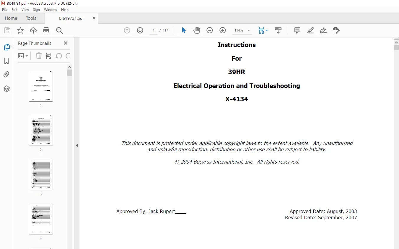
CAT BUCYRUS 39HR Electrical Operation and Troubleshooting Instructions Manual X-4134 – PDF DOWNLOAD
$25.95
CAT BUCYRUS 39HR Electrical Operation and Troubleshooting Instructions Manual X-4134 – PDF DOWNLOAD
Description
CAT BUCYRUS 39HR Electrical Operation and Troubleshooting Instructions Manual X-4134 – PDF DOWNLOAD
FILE DETAILS:
CAT BUCYRUS 39HR Electrical Operation and Troubleshooting Instructions Manual X-4134 – PDF DOWNLOAD
Language : English
Pages : 117
Downloadable : Yes
File Type : PDF
DESCRIPTION:
CAT BUCYRUS 39HR Electrical Operation and Troubleshooting Instructions Manual X-4134 – PDF DOWNLOAD
OVERVIEW
- The 39HR is a diesel-hydraulic drill designed by Bucyrus International Inc.® This instruction discusses its electrical control system.
- A separate instruction covers the operation of the operator display. Please refer to the hydraulic, diesel, and mechanical documentation for help with other features of the drill.
- This manual is written to help the user understand the workings and general operation of the 39HR electrical control system.
- Certain objects referred to in this manual and in the schematics as “options” are only present on drills where that particular feature has been purchased.
- On other systems, those items are either not wired or not functioning. It is important to read this manual with respect to the actual schematics supplied with your drill.
- Certain design enhancements may have been made to your machine, which improve the operation of various systems. Therefore, there may be some differences between the operation described in this manual and the actual operation of the drill.
GENERAL MACHINE DESCRIPTION
Drill Overview
The 39HR rotary blast hole drill incorporates 24VDC batteries, proportional hydraulics, a programmable logic controller (PLC), and other technically advanced devices in a form that promotes high performance and production, low operating costs, and operator comfort. All operator functions are electronically controlled and the ergonomically designed operator interface provides improved efficiency.
The rotary, hoist/pulldown, and propel motions are controlled by hydraulic valves. Each of these four valves has two distinct functions:
· Hoist and Left Track Propel Forward
· Pulldown and Left Track Propel Reverse
· Rotary Clockwise and Right Track Propel Forward
· Rotary Counterclockwise and Right Track Propel Reverse
- The selected motion is controlled by the PLC. This control system determines which valve will be energized depending upon the function required (e.g., mast raise, pipe arm lower) and the mode of the drill (i.e., Propel, Drill, Mast/Winch). The head’s actual drive mechanism is rack and pinion, so no chains are used as part of the drive mechanism.
- In fact, the drill was designed to minimize all cabling attached to the head. The propel motion consists of dual independent crawler mechanisms that are hydraulically powered. Each hydraulic drive motor is connected to its respective drive tumbler by means of a heavy-duty gearbox.
- No chains are used in the propel drive train. Control of the hydraulic drive system is provided by electronically controlled proportional valves, as described in this manual. The hydraulics pumps are powered by direct coupling to the diesel engine. The output shafts of these are directly coupled to the compressor, which is used during the drilling operation to clear the chips out of the hole.
- The diesel/compressor startup sequence includes an electrically powered “easy start” system, which reduces initial load during startup.
IMAGES PREVIEW OF THE MANUAL:
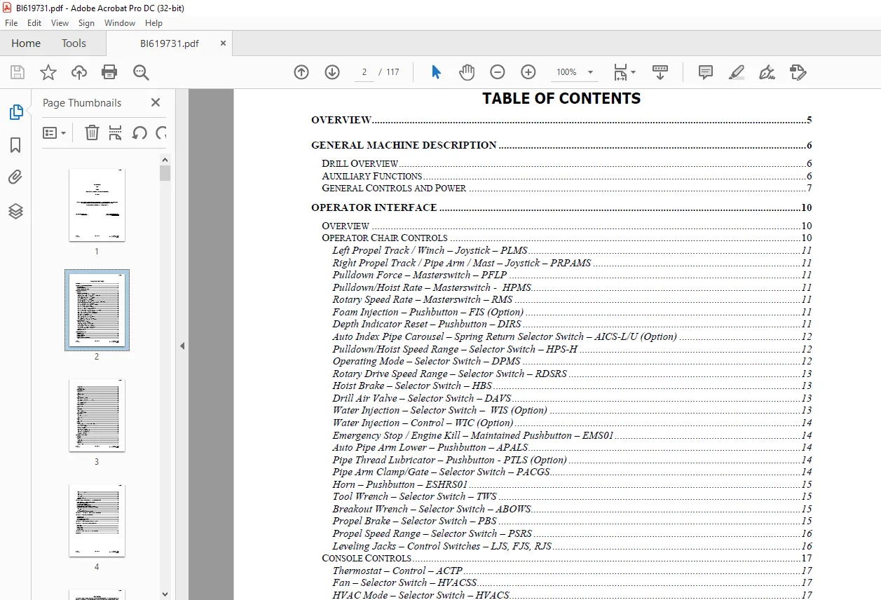
TABLE OF CONTENTS:
CAT BUCYRUS 39HR Electrical Operation and Troubleshooting Instructions Manual X-4134 – PDF DOWNLOAD
OVERVIEW 5
GENERAL MACHINE DESCRIPTION 6
DRILL OVERVIEW 6
AUXILIARY FUNCTIONS 6
GENERAL CONTROLS AND POWER 7
OPERATOR INTERFACE 10
OVERVIEW 10
OPERATOR CHAIR CONTROLS 10
Left Propel Track / Winch – Joystick – PLMS 11
Right Propel Track / Pipe Arm / Mast – Joystick – PRPAMS 11
Pulldown Force – Masterswitch – PFLP 11
Pulldown/Hoist Rate – Masterswitch – HPMS 11
Rotary Speed Rate – Masterswitch – RMS 11
Foam Injection – Pushbutton – FIS (Option) 11
Depth Indicator Reset – Pushbutton – DIRS 11
Auto Index Pipe Carousel – Spring Return Selector Switch – AICS-L/U (Option) 12
Pulldown/Hoist Speed Range – Selector Switch – HPS-H 12
Operating Mode – Selector Switch – DPMS 12
Rotary Drive Speed Range – Selector Switch – RDSRS 13
Hoist Brake – Selector Switch – HBS 13
Drill Air Valve – Selector Switch – DAVS 13
Water Injection – Selector Switch – WIS (Option) 13
Water Injection – Control – WIC (Option) 14
Emergency Stop / Engine Kill – Maintained Pushbutton – EMS01 14
Auto Pipe Arm Lower – Pushbutton – APALS 14
Pipe Thread Lubricator – Pushbutton – PTLS (Option) 14
Pipe Arm Clamp/Gate – Selector Switch – PACGS 14
Horn – Pushbutton – ESHRS01 15
Tool Wrench – Selector Switch – TWS 15
Breakout Wrench – Selector Switch – ABOWS 15
Propel Brake – Selector Switch – PBS 15
Propel Speed Range – Selector Switch – PSRS 16
Leveling Jacks – Control Switches – LJS, FJS, RJS 16
CONSOLE CONTROLS 17
Thermostat – Control – ACTP 17
Fan – Selector Switch – HVACSS 17
HVAC Mode – Selector Switch – HVACS 17
Boarding Stairs – Selector Switch – BSS2 17
Mainframe Lights – Selector Switch – EXLS1 18
Ground / Mast Lights – Selector Switch – EXLS2 18
Cab Light – Pushbutton/Control – CLDCP 18
Diesel / Gauge Panel 18
OPERATOR DISPLAY 18
MACHINE OPERATION 19
OVERVIEW 19
MACHINE STARTUP 19
MACHINE SHUTDOWN 19
CONTROL ENABLE 19
MACHINE SETUP AND CALIBRATION 20
Overview 20
Head Calibration 20
Setting Limits 21
Machine Settings 22
OPERATIONAL MODE 23
AIR COMPRESSOR 23
Startup 23
Drill Air 23
Venting 23
BOARDING STAIRS 24
Operation 24
Alarms 24
HOIST/PULLDOWN & ROTARY 24
Overview 24
Hoist/Pulldown – Speed, Direction, and Force 24
Hoist/Pulldown Brake 25
Rotary 25
Rotary Speed Feedback 26
JACKS & LEVELING 26
Operation 26
Retract Switch 27
MAST 27
Operation 27
OIL COOLERS 27
Overview 27
Hydraulic Oil Cooler 27
Compressor Oil Cooler 27
PIPE HANDLING 28
Overview 28
Raising/Lowering Pipe Arm 28
Auto Lower 28
Clamp & Gate 29
PROPEL 29
Overview 29
Propel Brakes 29
WINCH 30
OPTIONS 30
Air Compressor Variable Volume Control (Option) 30
Bit Lubricator (Option) 31
Cold Temperature (Option) 31
Fire Suppression (Option) 31
Foam Injection (Option) 31
Multi-Pipe Carousel (Option) 31
Pipe Thread Lubricator (Option) 32
Radio Remote Propel (Option) 32
Water Injection (Option) 35
Windshield Wipers (Option) 35
CONTROL SYSTEM (PLC) 36
OVERVIEW 36
NETWORK 36
Overview 36
Connections 37
Node Settings 38
HARDWARE 39
Overview 39
Standard “Racks” 39
BI619731
X-4134 Page 4 of 117 Issued August, 2003
Jack Rupert Re-issued September, 2007
X-4134
Processor 40
Communication Cards 41
Digital Inputs 41
Digital Outputs 42
Analog Inputs 43
Analog Outputs 43
Additional Components 44
PLC RESET 44
STARTUP, TESTS, ADJUSMENTS, & TROUBLESHOOTING 45
PRELIMINARY COMMISSIONING CABLING CHECKS 45
MAIN POWER SYSTEM CHECKS 45
DC POWER SUPPLY CHECKS 45
CONTROL SYSTEM TROUBLESHOOTING 46
DIGITAL HYDRAULIC VALVES ELECTRICAL CHECKS 47
PROPORTIONAL HYDRAULIC VALVES ELECTRICAL CHECKS 47
Overview 47
Integrated Valves 47
Non-Integrated Valves 48
HEAD ENCODER CHECKS AND REPLACEMENT 52
APPENDIX A – CAB DISPLAY ALARMS (CDA MESSAGES) 55
APPENDIX B – PLC LED DIAGNOSTICS 85
PROCESSOR LED’S 85
REMOTE I/O LED’S 88
ANALOG INPUT / OUTPUT CARDS 89
HEAD ENCODER LED’S 90
APPENDIX C – PLC DIAGNOSTIC BUFFER EVENTS 91
APPENDIX D – PROFIBUS NODE DIAGNOSTICS 111
NODE STATE 111
ERROR TYPE 111
MODULE STATE 111
CHANNEL TYPE 111
CHANNEL ERROR 111
APPENDIX E – CAB RACK ANALOG DIAGNOSTICS 116
REVISIONS 117
Need help? Contact: [email protected]
PLEASE NOTE:
- This is the SAME exact manual used by your dealers to fix your vehicle.
- The same can be yours in the next 2-3 mins as you will be directed to the download page immediately after paying for the manual.
- Any queries / doubts regarding your purchase, please feel free to contact [email protected]
S.M