Cat Bucyrus 400 600 700 1000 1250 1500 PanelView Plus Terminals User Manual 2711P – PDF DOWNLOAD
$28.95
Cat Bucyrus 400 600 700 1000 1250 1500 PanelView Plus Terminals User Manual 2711P – PDF DOWNLOAD
Description
Cat Bucyrus 400 600 700 1000 1250 1500 PanelView Plus Terminals User Manual 2711P – PDF DOWNLOAD
FILE DETAILS:
Cat Bucyrus 400 600 700 1000 1250 1500 PanelView Plus Terminals User Manual 2711P – PDF DOWNLOAD
Language : English
Pages : 249
Downloadable : Yes
File Type : PDF
IMAGES PREVIEW OF THE MANUAL:
DESCRIPTION:
Cat Bucyrus 400 600 700 1000 1250 1500 PanelView Plus Terminals User Manual 2711P – PDF DOWNLOAD
This preface provides information on these topics.
• Intended audience
• Parts list
• Additional resources
• Software and firmware upgrades
Intended Audience :
- Use this manual if you are responsible for installing, operating, or
troubleshooting the PanelView Plus or PanelView Plus CE terminals. - No special knowledge is required to understand this manual or
operate the terminal. However, you must understand the functions
and operations of FactoryTalk View Machine Edition (ME)
applications that will run on the terminal. Consult the application
designer for this information. - Equipment installers must be familiar with standard panel installation
techniques.
Parts List:
The PanelView Plus terminals are shipped with these items.
• Power terminal block
• FactoryTalk View ME runtime software, preloaded
• Mounting levers for 400 and 600 terminals, quantity eight
• Mounting clips for 700 to 1500 terminals, quantity four to eight
• Installation instructions
• Panel cutout template
Additional items are shipped with the PanelView Plus CE terminals.
• Windows CE .NET operating system preloaded with Terminal
Services and Internet Explorer
• PanelView Plus CE Accessory CD with utilities and software
development kit for C++
• Microsoft Windows CE license agreement
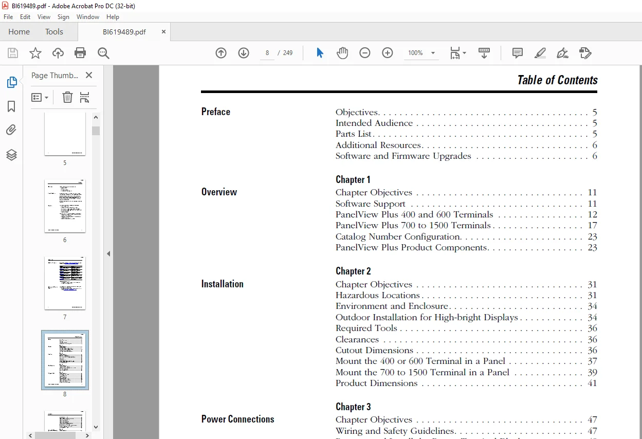
TABLE OF CONTENTS:
Cat Bucyrus 400 600 700 1000 1250 1500 PanelView Plus Terminals User Manual 2711P – PDF DOWNLOAD
GD12325545_1.pdf........................................................................................................................................................................................................  0
	2711P-UM001H-EN-P, PanelView Plus Terminals.........................................................................................................................................................................  3
	Important User Information..........................................................................................................................................................................................  3
	Summary of Changes..................................................................................................................................................................................................  4
	Preface.............................................................................................................................................................................................................  6
		Objectives......................................................................................................................................................................................................  6
		Intended Audience...............................................................................................................................................................................................  6
		Parts List......................................................................................................................................................................................................  6
		Additional Resources............................................................................................................................................................................................  7
		Software and Firmware Upgrades..................................................................................................................................................................................  7
	Table of Contents...................................................................................................................................................................................................  8
	1 - Overview........................................................................................................................................................................................................ 12
		Chapter Objectives.............................................................................................................................................................................................. 12
		Software Support................................................................................................................................................................................................ 12
		PanelView Plus 400 and 600 Terminals............................................................................................................................................................................ 13
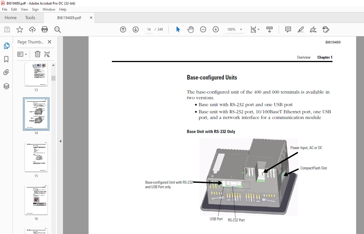
			Base-configured Units....................................................................................................................................................................................... 14
			Communication Modules....................................................................................................................................................................................... 15
			Power Options............................................................................................................................................................................................... 15
			Display and Input Options................................................................................................................................................................................... 16
				Touch Screen............................................................................................................................................................................................ 16
				Keypad or Keypad and Touch.............................................................................................................................................................................. 17
		PanelView Plus 700 to 1500 Terminals............................................................................................................................................................................ 18
			Modular Components.......................................................................................................................................................................................... 19
			Base-configured Unit........................................................................................................................................................................................ 19
			Logic Modules and CompactFlash.............................................................................................................................................................................. 20
			Communication Modules....................................................................................................................................................................................... 20
			Power Options............................................................................................................................................................................................... 21
			Display Modules............................................................................................................................................................................................. 21
				Touch Screen............................................................................................................................................................................................ 22
				Keypad or Keypad and Touch.............................................................................................................................................................................. 23
		Catalog Number Configuration.................................................................................................................................................................................... 24
		PanelView Plus Product Components............................................................................................................................................................................... 24
	2 - Installation.................................................................................................................................................................................................... 32
		Chapter Objectives.............................................................................................................................................................................................. 32
		Hazardous Locations............................................................................................................................................................................................. 32
			USB Ports................................................................................................................................................................................................... 33
				Application Information................................................................................................................................................................................. 34
		Environment and Enclosure....................................................................................................................................................................................... 35
		Outdoor Installation for High-bright Displays................................................................................................................................................................... 35
		Required Tools.................................................................................................................................................................................................. 37
		Clearances...................................................................................................................................................................................................... 37
		Cutout Dimensions............................................................................................................................................................................................... 37
		Mount the 400 or 600 Terminal in a Panel........................................................................................................................................................................ 38
			1. Cut an opening in the panel by using the panel cutout shipped with the terminal.......................................................................................................................... 38
			2. If a communication module is ordered separately, attach the module to the base unit before panel installation............................................................................................ 38
			3. Make sure the terminal sealing gasket is properly positioned on the terminal............................................................................................................................. 38
			4. Install legend strips before installing the terminal if you are using keypad legend strips on a 600 keypad terminal...................................................................................... 38
			5. Place the terminal in the panel cutout................................................................................................................................................................... 38
			6. Insert all mounting levers into the mounting slots on the terminal....................................................................................................................................... 39
			7. When all levers are in place, slide each lever an additional notch or two until you hear a click......................................................................................................... 39
			8. Rotate each lever in the direction indicated until it is in the final latch position..................................................................................................................... 39
		Mount the 700 to 1500 Terminal in a Panel....................................................................................................................................................................... 40
			1. Cut an opening in the panel by using the panel cutout shipped with the terminal.......................................................................................................................... 40
			2. Make sure the terminal sealing gasket is properly positioned on the terminal............................................................................................................................. 40
			3. Install the legend strips before installing the terminal if you are using keypad legend strips on keypad terminals....................................................................................... 40
			4. Place the terminal in the panel cutout................................................................................................................................................................... 40
			5. Slide the ends of the mounting clips into the slots on the terminal...................................................................................................................................... 41
			6. Tighten the mounting clip screws by hand until the gasket seal contacts the mounting surface uniformly................................................................................................... 41
			7. Tighten the mounting clips screws to a torque of 0.90…1.1 Nm (8…10 lb.in) by using the specified sequence, making sure not to overtighten................................................................ 41
		Product Dimensions.............................................................................................................................................................................................. 42
	3 - Power Connections............................................................................................................................................................................................... 48
		Chapter Objectives.............................................................................................................................................................................................. 48
		Wiring and Safety Guidelines.................................................................................................................................................................................... 48
		Remove and Install the Power Terminal Block..................................................................................................................................................................... 49
			400 and 600 Terminals....................................................................................................................................................................................... 49
				1. Insert the tip of small, flat-blade, screwdriver into the terminal block access slot................................................................................................................. 49
				2. Gently pry the terminal block away from terminal to release the locking mechanism.................................................................................................................... 50
				1. Press terminal block base in first with block leaning outward........................................................................................................................................ 50
				2. Gently push the top of the terminal block back to the vertical position to snap in locking tab....................................................................................................... 50
			700 to 1500 Terminals....................................................................................................................................................................................... 50
				1. Loosen the two screws that secure the terminal block................................................................................................................................................. 51
				2. Gently pull the terminal block away from the connector............................................................................................................................................... 51
				1. Reattach the terminal block to the connector until seated............................................................................................................................................ 51
				2. Tighten the two screws that secure the terminal block to the connector............................................................................................................................... 51
		DC Power Connections............................................................................................................................................................................................ 52
			External Power Supply For Non-insolated DC Terminals........................................................................................................................................................ 53
			External Power for 700 to 1500 Isolated DC Terminals (2711P-RxxDx Logic Modules)............................................................................................................................ 54
			Earth/Ground Connection..................................................................................................................................................................................... 54
			Connect DC Power............................................................................................................................................................................................ 56
				1. Verify that the terminal is not connected to a power source.......................................................................................................................................... 56
				2. Secure the DC power wires to the terminal block...................................................................................................................................................... 56
				3. Secure the earth/ground wire......................................................................................................................................................................... 56
				4. Apply 24V DC power to the terminal................................................................................................................................................................... 56
		AC Power Connections............................................................................................................................................................................................ 57
			Protective Earth Connection................................................................................................................................................................................. 57
			Functional Earth Connection................................................................................................................................................................................. 58
			Connect AC Power............................................................................................................................................................................................ 59
				1. Verify that the terminal is not connected to a power source.......................................................................................................................................... 59
				2. Secure the AC power wires to the terminal block...................................................................................................................................................... 59
				3. Secure the protective earth/ground wire to the marked position of the power input terminal block..................................................................................................... 59
				4. On the 700 to 1500 devices, also secure the functional earth/ground wire to the functional earth terminal screw on the back of the display to ground bus............................................. 59
				5. Apply AC power to the terminal....................................................................................................................................................................... 59
		Reset the Terminals............................................................................................................................................................................................. 60
	4 - Configuration Mode.............................................................................................................................................................................................. 62
		Chapter Objectives.............................................................................................................................................................................................. 62
		Access Configuration Mode....................................................................................................................................................................................... 62
			Navigation Buttons.......................................................................................................................................................................................... 64
			Enter or Edit Data.......................................................................................................................................................................................... 65
				1. Select a character on the character keyboard......................................................................................................................................................... 65
				2. Press the Select button to copy the character to the display area.................................................................................................................................... 65
				3. Press Enter when done to exit the input panel........................................................................................................................................................ 65
		Load an Application............................................................................................................................................................................................. 66
			1. Select Load Application from the main screen............................................................................................................................................................. 66
			2. Press the Source button to select the storage location of the application file you want to load.......................................................................................................... 66
			3. Select an .MER file from the list by using the up and down cursor keys................................................................................................................................... 66
			4. Press the Load button to load the selected application................................................................................................................................................... 66
			5. Select Yes or No......................................................................................................................................................................................... 66
		Run an Application.............................................................................................................................................................................................. 67
		Application Settings............................................................................................................................................................................................ 67
		Terminal Settings............................................................................................................................................................................................... 67
			1. Select Terminal Settings from the main screen............................................................................................................................................................ 68
			2. Highlight an option by using the up and down cursor buttons.............................................................................................................................................. 68
			3. Press the Enter key to access the highlighted function................................................................................................................................................... 68
		Configure Communications........................................................................................................................................................................................ 68
			KEPServer Serial Port ID’s.................................................................................................................................................................................. 68
			Configure Communication Properties.......................................................................................................................................................................... 69
				1. Select Terminal Settings>Networks and Communications>RSLinx Enterprise Communications................................................................................................................ 69
				2. Select the communication card installed on your terminal............................................................................................................................................. 69
				3. Press the Edit Driver button to view the current properties for the communication driver............................................................................................................. 69
				4. Select the property you want to modify, then press the Edit button................................................................................................................................... 69
				5. Modify the setting and then press the Enter button................................................................................................................................................... 69
			Configure the Controller Address............................................................................................................................................................................ 72
				1. From the RSLinx Configuration screen, select a device node........................................................................................................................................... 72
				2. Press the Edit Device button to view the device name and current address of the logic controller..................................................................................................... 72
				3. Press the Device Address button to modify the address................................................................................................................................................ 72
				4. Use the Input Panel to modify the address and then press the Enter button............................................................................................................................ 72
				5. Press OK............................................................................................................................................................................................. 72
		Configure Network Information................................................................................................................................................................................... 73
			Define a Device Name for the Terminal....................................................................................................................................................................... 73
				1. Select Terminal Settings>Networks and Communications>Network Connections>Device Name................................................................................................................. 73
				2. Press the Device Name button to enter or edit the device name........................................................................................................................................ 73
				3. Press the Device Description button to enter or edit the description for the device.................................................................................................................. 73
				4. Press OK............................................................................................................................................................................................. 73
			Define an Ethernet IP Address............................................................................................................................................................................... 74
				1. Select Terminal Settings>Network and Communications>Network Connections>Network Adapters............................................................................................................. 74
				2. Press the IP Address button to view or modify the IP address......................................................................................................................................... 74
				3. Press the DHCP button to enable or disable DHCP assignment of addresses.............................................................................................................................. 74
				4. Press the IP address, Subnet Mask, and Gateway buttons, then enter the appropriate information....................................................................................................... 74
				5. Press OK when done................................................................................................................................................................................... 74
			Define Name Server Addresses................................................................................................................................................................................ 76
				1. Select Terminal Settings>Network and Communications>Network Connections>Network Adapters............................................................................................................. 76
				2. Press a button to enter a name server address........................................................................................................................................................ 76
				3. Press OK when done................................................................................................................................................................................... 76
			Authorize Terminal to Access Network Resources.............................................................................................................................................................. 77
				1. Select Terminal Settings>Network and Communications>Network Connections>Network Identification....................................................................................................... 77
				2. Press the user name, password and domain buttons and enter the information provided by your network administrator.................................................................................... 77
				3. Press OK when done................................................................................................................................................................................... 77
		Configure Diagnostics........................................................................................................................................................................................... 77
			Remote Log Destination...................................................................................................................................................................................... 78
			Message Routing............................................................................................................................................................................................. 78
		Manage Files on the Terminal.................................................................................................................................................................................... 79
			Delete an Application File or a Font File................................................................................................................................................................... 79
				1. Select Terminal Settings>File Management>Delete Files>Delete Applications or Delete Fonts............................................................................................................ 79
				2. Press the Source button to choose the storage location of the application or font file you want to delete............................................................................................ 79
				3. Select a file from the list.......................................................................................................................................................................... 79
				4. Press the Delete button.............................................................................................................................................................................. 79
				5. Select Yes or No when asked if you want to delete the selected application or font file from the storage location.................................................................................... 79
			Delete Log Files from Terminal.............................................................................................................................................................................. 80
				1. Select Terminal Settings>File Management>Delete Files>Delete Log Files............................................................................................................................... 80
				2. Select Yes or No..................................................................................................................................................................................... 80
			Copy an Application File or Font File....................................................................................................................................................................... 80
				1. Select Terminal Settings>File Management>Copy Files>Copy Applications or Copy Fonts.................................................................................................................. 80
				2. Press the Source button to choose the location of the application or font file you want to copy...................................................................................................... 80
				3. Select a file from the storage location.............................................................................................................................................................. 81
				4. Press the Destination button on the same screen...................................................................................................................................................... 81
				5. Press the Destination button to choose the storage location where you want to copy the application or font file...................................................................................... 81
				6. Press the Copy button to copy the selected application or font file to the selected destination...................................................................................................... 81
				7. Select Yes or No..................................................................................................................................................................................... 81
		Modify Display Settings......................................................................................................................................................................................... 82
			View the Display Temperature................................................................................................................................................................................ 82
			Adjust the Display Contrast................................................................................................................................................................................. 83
				1. Select Terminal Settings>Display>Display Contrast.................................................................................................................................................... 83
				2. Press the up an down cursor buttons to adjust the contrast........................................................................................................................................... 83
				3. Press OK when done................................................................................................................................................................................... 83
			Adjust the Display Intensity................................................................................................................................................................................ 83
				1. Select Terminal Settings>Display>Display Intensity................................................................................................................................................... 83
				2. Press the Startup Intensity button to switch between the Default intensity and the Runtime intensity................................................................................................. 83
				3. Increase or decrease the intensity for runtime operations, by pressing the up or down arrow keys..................................................................................................... 83
				4. Press OK when done................................................................................................................................................................................... 83
			Configure the Screen Saver.................................................................................................................................................................................. 84
				1. Select Terminal Settings>Display>Screen Saver........................................................................................................................................................ 84
				2. Press the Screen Saver button to select an idle timeout for activating the screen saver.............................................................................................................. 84
				3. Increase or decrease the brightness intensity of the screen saver by pressing the up and down cursor buttons......................................................................................... 84
				4. Press the Advanced Settings button to access the bitmap option....................................................................................................................................... 84
				5. Press OK to exit and return to the terminal settings................................................................................................................................................. 84
			Enable or Disable the Screen Cursor......................................................................................................................................................................... 85
				1. Select Terminal Settings>Display>Cursor.............................................................................................................................................................. 85
				2. Press the Enable Cursor button to enable or disable the cursor....................................................................................................................................... 85
				3. Press OK to exit and return to Terminal Settings..................................................................................................................................................... 85
		Font Linking.................................................................................................................................................................................................... 86
		Configure Keypad, Keyboard, or Mouse............................................................................................................................................................................ 87
			Configure Keyboard Settings................................................................................................................................................................................. 87
				1. Select Terminal Settings>Input Devices>Keyboard...................................................................................................................................................... 87
				2. Press the Repeat Rate button to specify the number of times a key is repeated per second when you hold a key down.................................................................................... 87
				3. Press the Repeat Delay button to select the amount of time that elapses per second before a key is repeated.......................................................................................... 87
				4. Press OK when done................................................................................................................................................................................... 87
			Configure Keypad Settings for the Terminal.................................................................................................................................................................. 88
				1. Select Terminal Settings>Input Devices>Keypad........................................................................................................................................................ 88
				2. Press the Single Key Mode button to select a key option.............................................................................................................................................. 88
				3. Press the Hold Off Time button to enter the length of time, in seconds, to ignore multiple presses of the same key................................................................................... 88
				4. Press OK when done................................................................................................................................................................................... 88
			Configure the Sensitivity of the Mouse...................................................................................................................................................................... 88
		Configure the Touch Screen...................................................................................................................................................................................... 89
			Calibrate the Touch-screen.................................................................................................................................................................................. 89
				1. Select Terminal Settings>Input Devices>Touch Screen>Calibration...................................................................................................................................... 89
				2. Touch the center of the target (+) each of the four times it appears on the screen................................................................................................................... 89
				3. Tap the screen to save the data or wait 30 seconds to cancel the saved data, retaining the current settings.......................................................................................... 89
			Enable or Disable the Cursor on Touch Screens............................................................................................................................................................... 90
				1. Select Terminal Settings>Input Devices>Touch Screen>Cursor........................................................................................................................................... 90
				2. Press the Enable Cursor button to enable or disable the cursor....................................................................................................................................... 90
				3. Press OK............................................................................................................................................................................................. 90
			Set the Double-tap Sensitivity.............................................................................................................................................................................. 91
				1. Select Terminal Settings>Input Devices>Touch Screen>Double-tap Sensitivity........................................................................................................................... 91
				2. Double-tap the Set button to set the sensitivity of touch-screen presses............................................................................................................................. 91
				3. Double-tap the Test button to test the sensitivity of touch-screen presses........................................................................................................................... 91
				4. Press OK when done................................................................................................................................................................................... 91
		Configure Print Options......................................................................................................................................................................................... 92
			1. Select a Terminal Settings>Networks and Communications>Print Setup> option............................................................................................................................... 92
			2. Update properties by selecting the appropriate button and changing the value, if necessary............................................................................................................... 92
			3. Press the Advanced button to access additional settings.................................................................................................................................................. 92
			4. Press OK when done....................................................................................................................................................................................... 93
			5. Press OK to return to Terminal Settings.................................................................................................................................................................. 93
		Configure Startup Options....................................................................................................................................................................................... 94
			1. Select Terminal Settings>Startup Options>FactoryTalk View ME Station Startup............................................................................................................................. 94
			2. Press the On Startup button until Do not start FactoryTalk View ME is selected........................................................................................................................... 94
			3. Press OK................................................................................................................................................................................................. 94
			Enter Configuration Mode on Startup......................................................................................................................................................................... 95
				1. Select Terminal Settings>Startup Options>FactoryTalk View ME Station Startup......................................................................................................................... 95
				2. Press the On Startup button to select Go to Configuration Mode....................................................................................................................................... 95
				3. Press the Configuration Mode Options button.......................................................................................................................................................... 95
				4. Press the Load Current Application button to specify whether you want to load the current application on startup..................................................................................... 95
				5. Press the Replace RSLinx Communications button to specify whether to use the communication configuration of the current application or the terminal on startup....................................... 95
				6. Press OK to return to the previous screen............................................................................................................................................................ 95
				7. Press OK to return to Terminal Settings.............................................................................................................................................................. 95
			Run the Loaded Application on Startup....................................................................................................................................................................... 96
				1. Select Terminal Settings>Startup Options>FactoryTalk View ME Station Startup......................................................................................................................... 96
				2. Press the On Startup button to select Run Current Application........................................................................................................................................ 96
				3. Press the Replace RSLinx Communications button to specify what configuration settings to use when running the application............................................................................ 96
				4. Press the Delete Log Files to specify what action to take with the log files on startup.............................................................................................................. 96
				5. Press OK twice to return to Terminal Settings........................................................................................................................................................ 96
			Startup Shortcuts for PanelView Plus CE Devices............................................................................................................................................................. 97
				Start without Loading or Running .MER Application....................................................................................................................................................... 97
				Start FactoryTalk View ME Station Software and Load .MER Application.................................................................................................................................... 98
				Start FactoryTalk View ME Station and Run .MER Application.............................................................................................................................................. 98
				Other Shortcut Paths for FactoryTalk View ME Station Software........................................................................................................................................... 99
		Configure Startup Tests.........................................................................................................................................................................................100
			Select Tests to Run on Startup..............................................................................................................................................................................100
				1. Select Terminal Settings>Startup Options>Startup Tests...............................................................................................................................................100
				2. Select the tests you want to run on startup..........................................................................................................................................................100
				3. Press OK.............................................................................................................................................................................................100
			Configure Startup Test Settings.............................................................................................................................................................................101
				1. Select Terminal Settings>Startup Options>Startup Test Settings.......................................................................................................................................101
				2. Press the Repeat Count button to specify the number of times, 0… 128, to run the selected tests on startup...........................................................................................101
				3. Press the Enable Extended Diagnostics button to enable or disable extended diagnostics on startup....................................................................................................101
				4. Press OK.............................................................................................................................................................................................101
		View and Clear the System Event Log.............................................................................................................................................................................102
			1. Select Terminal Settings>System Event Log................................................................................................................................................................102
			2. Select an event and then press the More Details button to display system event log details for that event................................................................................................102
			3. Press the Clear All button to clear all system event logs................................................................................................................................................102
			4. Press OK.................................................................................................................................................................................................102
		Display Terminal Information....................................................................................................................................................................................103
			1. Select Terminal Settings>System>Information>Terminal Information.........................................................................................................................................103
			2. Press the Memory Allocation button to view or adjust the:................................................................................................................................................104
			3. Press the Up or Down button to increase or decrease the allocation of storage or program memory..........................................................................................................104
			4. Press OK to return to previous screen....................................................................................................................................................................104
			5. Press OK to return to terminal settings..................................................................................................................................................................104
		Display FactoryTalk View ME Station Information.................................................................................................................................................................105
			1. Select Terminal Settings>System>Information>About FactoryTalk View ME Station............................................................................................................................105
			2. Press the Technical Support button, if desired...........................................................................................................................................................105
			3. Press Close..............................................................................................................................................................................................105
		Modify the Date, Time, or Time Zone.............................................................................................................................................................................106
			Change the Date.............................................................................................................................................................................................106
				1. Select Terminal Settings>Time/Date/Regional Settings>Date............................................................................................................................................106
				2. Press the Year, Month, and Day buttons to change the values..........................................................................................................................................106
				3. Press OK when done...................................................................................................................................................................................106
			Change the Time.............................................................................................................................................................................................107
				1. Select Terminal Settings>Time/Date/Regional Settings>Time............................................................................................................................................107
				2. Press the Hour, Minute, and Seconds buttons to change the values.....................................................................................................................................107
				3. Press OK when done...................................................................................................................................................................................107
			Change the Time Zone........................................................................................................................................................................................108
				1. Select Terminal Settings>Time/Date/Regional Settings>Time Zone.......................................................................................................................................108
				2. Press the up and down cursor buttons to select a time zone...........................................................................................................................................108
				3. Press the Daylight Savings button to enable or disable daylight savings for the selected time zone...................................................................................................108
				4. Press the Use Daylight Savings Button to select Yes or No............................................................................................................................................109
				5. Click OK when done...................................................................................................................................................................................109
				6. Click OK to return to Terminal Settings..............................................................................................................................................................109
		Modify Regional Settings........................................................................................................................................................................................109
			Select a Language...........................................................................................................................................................................................109
				1. Select Terminal Settings>Time/Date/Regional Settings>Regional Settings>Language......................................................................................................................109
				2. Select a language by pressing the up and down cursor keys............................................................................................................................................109
				3. Press OK.............................................................................................................................................................................................110
			Change the Decimal Separator for Numeric Formats............................................................................................................................................................110
				1. Select Terminal Settings>Time/Date/Regional Settings>Regional Settings>Numeric Format................................................................................................................110
				2. Enter up to three characters for the new separator...................................................................................................................................................110
				3. Click OK.............................................................................................................................................................................................110
			Change the Time Format......................................................................................................................................................................................111
				1. Select Terminal Settings>Time/Date/Regional Settings>Regional Settings>Time Format...................................................................................................................111
				2. Press the appropriate buttons to adjust the formats..................................................................................................................................................111
				3. Click OK.............................................................................................................................................................................................111
			Change the Short Date Format................................................................................................................................................................................112
				1. Select Terminal Settings>Time/Date/Regional Settings>Regional Settings>Short Date Format.............................................................................................................112
				2. Press the Format button to select an available format................................................................................................................................................112
				3. Press the Separator button to change the field separator for the date elements.......................................................................................................................112
				4. Click OK when done...................................................................................................................................................................................112
			Change the Long Date Format.................................................................................................................................................................................113
				1. Select Terminal Settings>Time/Date/Regional Settings>Regional Settings>Long Date Format..............................................................................................................113
				2. Press the Long Date Format button to select a date format............................................................................................................................................113
				3. Click OK when done...................................................................................................................................................................................113
	5 - Windows CE .NET Operating System................................................................................................................................................................................114
		Chapter Objectives..............................................................................................................................................................................................114
		Windows CE .NET Architecture....................................................................................................................................................................................114
			Windows CE .NET Benefits....................................................................................................................................................................................114
			Compile Windows CE .NET Applications........................................................................................................................................................................115
		Windows CE .NET Programs........................................................................................................................................................................................115
			Install Applications........................................................................................................................................................................................116
		Windows CE .NET Operating System................................................................................................................................................................................116
			Start Menu and Taskbar......................................................................................................................................................................................118
			Command Bar.................................................................................................................................................................................................118
			Find Files..................................................................................................................................................................................................119
			Browse Web Pages............................................................................................................................................................................................119
			Print.......................................................................................................................................................................................................119
		PanelView Plus CE Memory........................................................................................................................................................................................120
			Boot ROM....................................................................................................................................................................................................120
			Internal CompactFlash.......................................................................................................................................................................................120
			Dynamic RAM.................................................................................................................................................................................................121
			External CompactFlash Cards.................................................................................................................................................................................121
			USB Mass Storage Devices....................................................................................................................................................................................121
		Control Panel Applications......................................................................................................................................................................................122
			Owner.......................................................................................................................................................................................................123
				Network ID..............................................................................................................................................................................................123
				Identification and Notes................................................................................................................................................................................124
			Password....................................................................................................................................................................................................124
			Dialing.....................................................................................................................................................................................................124
			Network and Dial-up Connections.............................................................................................................................................................................125
				ActiveSync Connection...................................................................................................................................................................................125
				Configure Ethernet Connection...........................................................................................................................................................................125
					1. Select the Network and Dial-up Connections application...........................................................................................................................................125
					2. Click the PCI-E100CE1 icon to configure Ethernet settings........................................................................................................................................125
					3. On the IP address tab, select Obtain an IP address via DHCP or Specify an IP Address.............................................................................................................125
					4. Click OK in the title bar........................................................................................................................................................................126
					5. For the built-in Ethernet Controller, you must restart the terminal..............................................................................................................................126
					6. Click OK to close the Network Configuration dialog...............................................................................................................................................126
			PC Connection...............................................................................................................................................................................................126
			Touch.......................................................................................................................................................................................................127
				Double-tap Sensitivity..................................................................................................................................................................................127
				Calibration.............................................................................................................................................................................................127
			Keyboard....................................................................................................................................................................................................128
			Keypad......................................................................................................................................................................................................129
				When done performing operations, remember to click OK in the title bar to activate settings.............................................................................................................129
				Key Repeat..............................................................................................................................................................................................129
				Multi-Key/Hold-Off Lockout..............................................................................................................................................................................129
			Mouse.......................................................................................................................................................................................................130
			Input Panel.................................................................................................................................................................................................130
			Display.....................................................................................................................................................................................................131
				When done performing operations, remember to click OK in the title bar to activate settings.............................................................................................................131
				Background..............................................................................................................................................................................................131
				Appearance..............................................................................................................................................................................................131
				Backlight...............................................................................................................................................................................................132
				Screen Saver............................................................................................................................................................................................132
				Cursor..................................................................................................................................................................................................132
			Extended Diagnostics........................................................................................................................................................................................133
				Iteration Count.........................................................................................................................................................................................133
				Tests...................................................................................................................................................................................................134
			Hardware Monitor............................................................................................................................................................................................135
				When done performing operations, remember to click OK in the title bar to activate settings.............................................................................................................135
				Voltages and Temperature................................................................................................................................................................................135
				Event Log...............................................................................................................................................................................................135
			Power.......................................................................................................................................................................................................135
			System......................................................................................................................................................................................................136
				General.................................................................................................................................................................................................136
				Memory..................................................................................................................................................................................................136
				Device Name.............................................................................................................................................................................................137
				Copyrights..............................................................................................................................................................................................137
			Date/Time...................................................................................................................................................................................................138
			Regional Settings...........................................................................................................................................................................................138
				Language................................................................................................................................................................................................138
				Time....................................................................................................................................................................................................139
				Date....................................................................................................................................................................................................139
				Number..................................................................................................................................................................................................139
			Internet Options............................................................................................................................................................................................140
			Certificates................................................................................................................................................................................................140
			Remove Programs.............................................................................................................................................................................................141
			Storage Manager.............................................................................................................................................................................................141
	6 - Install and Replace Components..................................................................................................................................................................................142
		Chapter Objectives..............................................................................................................................................................................................142
		Required Tools..................................................................................................................................................................................................142
		Precautions.....................................................................................................................................................................................................142
		Component Compatibility for PanelView Plus CE Terminals.........................................................................................................................................................143
		Component Compatibility for PanelView Plus Terminals............................................................................................................................................................143
			Compatibility After Upgrade.................................................................................................................................................................................144
		Install RAM or Internal CompactFlash............................................................................................................................................................................144
			1. Remove power from the terminal...........................................................................................................................................................................144
			2. Place the terminal, display side down, on a flat stable surface..........................................................................................................................................144
			3. Loosen the six captive screws that secure the logic module...............................................................................................................................................144
			4. Carefully lift the logic module away from the terminal and turn over to expose the circuit board.........................................................................................................144
			5. Locate the RAM module on the circuit board, pull the metal retaining clips away from the module, and slide out the module................................................................................145
			6. Insert the new RAM module at a 45 angle and snap down...................................................................................................................................................145
			7. Unscrew and remove the retaining clip that secures the internal CompactFlash card........................................................................................................................145
			8. Pull out the internal CompactFlash card..................................................................................................................................................................145
			9. Insert the new internal CompactFlash card................................................................................................................................................................145
			10. Reattach the retaining clip.............................................................................................................................................................................145
			11. Attach the logic module by aligning the two connectors on the bottom of module with the connectors on the display module................................................................................145
			12. Push down on the logic module until firmly seated.......................................................................................................................................................145
			13. Tighten the six captive screws that secure the logic module to a torque of 0.58 Nm (5…7 lb.in)..........................................................................................................145
		Install or Replace the Logic Module.............................................................................................................................................................................145
			1. Disconnect power from the terminal.......................................................................................................................................................................145
			2. Set the terminal, display side down, on a clean, flat, stable surface to prevent scratches, if the terminal is removed from panel........................................................................145
			3. Position the logic module over the back of the display module until the two connectors on the bottom of the logic module align with the connectors on the display module.................................145
			4. Push down on the logic module until firmly seated........................................................................................................................................................146
			5. 1Tighten the six captive screws that secure the logic module to the display module to a torque of 0.58 Nm (5…7 lb.in)....................................................................................146
			1. Disconnect power from the terminal.......................................................................................................................................................................147
			2. Disconnect all power and communication cables............................................................................................................................................................147
			3. Set the terminal, display side down, on a clean, flat, stable surface to prevent scratches, if the terminal is removed from panel........................................................................147
			4. Remove the four screws that attach the communication module, if attached, to the logic module and carefully lift the communication module away from the logic module.....................................147
			5. Loosen the six captive screws that secure the logic module to the display module.........................................................................................................................147
			6. Carefully lift the logic module away from the back of the display module.................................................................................................................................147
			7. If reusing the memory in the new logic module:...........................................................................................................................................................147
			8. Install the new logic module.............................................................................................................................................................................147
			9. Attach the communication module, if necessary............................................................................................................................................................147
		Install or Replace a Communication Module.......................................................................................................................................................................148
			PanelView Plus 700 to 1500 Terminals........................................................................................................................................................................148
				1. Disconnect power from the terminal...................................................................................................................................................................148
				2. Set the terminal, display side down, on a clean, flat, stable surface to prevent scratches if the terminal is removed from panel.....................................................................148
				3. Remove the label covering the communication module connector on the logic module.....................................................................................................................148
				4. Position the communication module over the logic module so that the connectors on bottom of module align with connectors on the logic module.........................................................148
				5. Push down on the communication module until the connectors are firmly seated.........................................................................................................................149
				6. Tighten the four screws that secure the communication module to the logic module to a torque of 0.58 Nm (5…7 lb.in)..................................................................................149
				1. Disconnect power from the terminal...................................................................................................................................................................149
				2. Disconnect the communication cables from the module..................................................................................................................................................149
				3. Remove the four screws that secure the communication module to the logic module......................................................................................................................149
				4. Carefully lift the communication module away from the logic module and set aside.....................................................................................................................149
				5. Install the new communication module.................................................................................................................................................................149
			PanelView Plus 400 and 600 Terminals........................................................................................................................................................................150
				1. Disconnect power from the terminal...................................................................................................................................................................150
				2. Set the terminal, display side down, on a clean, flat, stable surface................................................................................................................................150
				3. Remove the label covering the connectors on the base unit of the terminal............................................................................................................................150
				4. Position the communication module over back of the terminal so that the connector on bottom of communication module align with the connector on the base unit........................................150
				5. Push down on the communication module until the connector is firmly seated...........................................................................................................................151
				6. Tighten the three captive screws that secure the module to the terminal, starting with the bottom, left screw on the module. Tighten screws to a torque of 0.34…0.45 Nm (3…4 lb.in)..................151
				1. Disconnect power from the terminal...................................................................................................................................................................151
				2. Disconnect the communication cables from the module..................................................................................................................................................151
				3. Loosen the three screws that secure the communication module to the terminal.........................................................................................................................151
				4. Carefully lift the communication module away from the terminal and set aside.........................................................................................................................151
				5. Install the new communication module.................................................................................................................................................................151
		Replace the Display Module......................................................................................................................................................................................152
			1. Disconnect power from the terminal.......................................................................................................................................................................152
			2. Remove the terminal from the panel.......................................................................................................................................................................152
			3. Detach the communication module, if attached, from the logic module by removing the four screws..........................................................................................................152
			4. Loosen the six captive screws that attach the logic module to the display module.........................................................................................................................152
			5. Carefully lift the logic module from the terminal........................................................................................................................................................152
			6. Set the display module aside.............................................................................................................................................................................152
			7. Position the new logic module over the new display module so that the connectors align...................................................................................................................153
			8. Push down on the logic module until firmly seated........................................................................................................................................................153
			9. Tighten the six captive screws that secure the logic module to the display module to a torque of 0.58 Nm (5…7 lb.in).....................................................................................153
			10. Attach the communication module (if necessary) and tighten the four screws to a torque of 0.58 Nm (5…7 lb.in)...........................................................................................153
		Replace the Battery.............................................................................................................................................................................................154
			1. Disconnect power from the terminal.......................................................................................................................................................................154
			2. Place the terminal, display side down, on a flat stable surface..........................................................................................................................................154
			3. Detach the communication module, if attached, from the logic module by removing the four screws..........................................................................................................154
			4. Loosen the six captive screws that attach the logic module to the display module.........................................................................................................................154
			5. Carefully lift the logic module away from the terminal and flip over to expose the circuit board.........................................................................................................155
			6. Locate the battery on the circuit board..................................................................................................................................................................155
			7. Remove the battery by lifting up the side of the battery.................................................................................................................................................155
			8. Insert the new battery...................................................................................................................................................................................155
			9. Attach the logic module by aligning the two connectors on the bottom of the module with the connectors on the terminal...................................................................................155
			10. Push down on the logic module until firmly seated.......................................................................................................................................................155
			11. Tighten the six captive screws that secure the logic module to a torque of 0.58 Nm (5…7 lb.in)..........................................................................................................155
			12. Attach the communication module (if necessary) and tighten the four screws to a torque of 0.58 Nm (5…7 lb.in)...........................................................................................155
		Replace the Bezel...............................................................................................................................................................................................156
			Remove the Display Module Bezel.............................................................................................................................................................................156
				1. Disconnect power from the terminal...................................................................................................................................................................156
				2. Set the terminal, display side down, on a flat stable surface........................................................................................................................................156
				3. On touch screen only terminals, remove the two screws that secure the small metal plate to the back of the display module............................................................................156
				4. Disconnect the touch screen connector................................................................................................................................................................156
				5. Remove the screws from the back of the display module................................................................................................................................................156
				6. Remove the sealing gasket............................................................................................................................................................................157
				7. Lift the back of the display module away from the bezel..............................................................................................................................................157
				8. Detach all connectors, maximum of three..............................................................................................................................................................157
				9. Set the bezel aside..................................................................................................................................................................................157
			Replace the Display Module Bezel............................................................................................................................................................................158
				1. Make sure the bezel is free of lint and marks before attaching.......................................................................................................................................158
				2. Attach the connectors................................................................................................................................................................................158
				3. Place the back of the display module over the bezel..................................................................................................................................................158
				4. Attach the touch screen connector....................................................................................................................................................................158
				5. Replace the sealing gasket...........................................................................................................................................................................158
				6. Attach the screws that secure the display module to the bezel and tighten to a torque of 1.35…1.58 Nm (12…14 lb.in)..................................................................................158
				7. On touch screen terminals, reattach the small metal plate to the back of the display module using two screws and torque to 0.58 Nm (5…7 lb.in).......................................................158
		Replace the Backlight...........................................................................................................................................................................................159
			1. Disconnect power from the terminal.......................................................................................................................................................................159
			2. Remove the display module bezel..........................................................................................................................................................................159
			3. Remove the four screws that secure the display bracket for the 700 series C display......................................................................................................................159
			4. Remove the four screws that secure the LCD display for all other displays................................................................................................................................159
			5. Lift the LCD display and detach the display connector from the circuit board.............................................................................................................................159
			6. Detach the backlight connectors from the circuit board...................................................................................................................................................160
			7. Follow these steps for the PanelView Plus 700 and 1000 displays..........................................................................................................................................160
			a. Press the retaining tab that secures the backlight and then pull out the backlight.......................................................................................................................160
			b. Insert the new backlight.................................................................................................................................................................................161
			8. Follow these steps for the PanelView Plus 1250 and 1500 displays.........................................................................................................................................161
			a. Remove the screws that secure the backlights and remove the backlights...................................................................................................................................161
			b. Insert the new backlights and then secure each with the same screws from the previous step and torque to 0.117 Nm (1.04 lb.in)...........................................................................161
			9. Attach the LCD display connector to the circuit board....................................................................................................................................................162
			10. Attach the backlight connector to the circuit board.....................................................................................................................................................162
			11. Secure the LCD display..................................................................................................................................................................................162
			a. Attach the display bracket then secure the display in the bracket for the 700 series C display...........................................................................................................162
			b. Attach the four screws for all othe displays.............................................................................................................................................................162
			12. Replace the display module bezel........................................................................................................................................................................162
		Remove the Product ID Label.....................................................................................................................................................................................162
			1. Remove the Allen-Bradley label using your fingers or a tweezers..........................................................................................................................................162
			2. Clean area with damp cloth and isopropyl alcohol.........................................................................................................................................................162
			3. Remove adhesive backing of OEM label and affix over area where label was located.........................................................................................................................162
		Replace the Keypad Legend Inserts...............................................................................................................................................................................163
			PanelView Plus 600 Terminal.................................................................................................................................................................................163
				1. From the rear of the unit, pull the legend strips out from the slots on the lower side of the terminal...............................................................................................163
				2. Slide the new insert into the same slot until only the end tab is visible............................................................................................................................163
			PanelView Plus 700 to 1500 Terminals........................................................................................................................................................................164
				1. Remove power from the terminal.......................................................................................................................................................................164
				2. Remove the display module bezel......................................................................................................................................................................164
				3. Pull the legend inserts out from the slots on the bezel..............................................................................................................................................164
				4. Slide the new legend strips into the same slots until only the end tab is visible....................................................................................................................164
				5. Replace the display module bezel.....................................................................................................................................................................164
		Use an External CompactFlash Card...............................................................................................................................................................................165
			Insert a CompactFlash Card..................................................................................................................................................................................165
			Remove a CompactFlash Card..................................................................................................................................................................................166
	7 - Terminal Connections............................................................................................................................................................................................168
		Chapter Objectives..............................................................................................................................................................................................168
		Wiring and Safety Guidelines....................................................................................................................................................................................168
		Logic Controller Cable Charts...................................................................................................................................................................................169
			Runtime Communication Cables - To Controller................................................................................................................................................................169
		Communication Port Isolation....................................................................................................................................................................................172
		USB Ports.......................................................................................................................................................................................................173
		Serial Connections..............................................................................................................................................................................................174
			Modem Connection............................................................................................................................................................................................175
			Construct a Null Modem Cable................................................................................................................................................................................175
			Computer Connections........................................................................................................................................................................................176
		Ethernet Connections............................................................................................................................................................................................177
			Ethernet Connector..........................................................................................................................................................................................177
			Ethernet Cable..............................................................................................................................................................................................178
			Security Considerations.....................................................................................................................................................................................178
		DH-485/DH+/Remote I/O Module....................................................................................................................................................................................179
			DH-485 Network Port Wiring for 700 to 1500 Terminals........................................................................................................................................................181
			DH-485 Connections for 400 and 600 Terminals................................................................................................................................................................182
			DH+ Network Connections.....................................................................................................................................................................................183
			Remote I/O Connections......................................................................................................................................................................................184
		ControlNet Module...............................................................................................................................................................................................185
			Related Information.........................................................................................................................................................................................185
			ControlNet Protocol.........................................................................................................................................................................................185
			Compatible ControlNet Controllers...........................................................................................................................................................................185
			Minimum Requirements........................................................................................................................................................................................186
			ControlNet Connections......................................................................................................................................................................................187
			NAP and Redundant Cables....................................................................................................................................................................................188
			Connect the Module to the Network...........................................................................................................................................................................188
		DeviceNet Module................................................................................................................................................................................................188
			Related Information.........................................................................................................................................................................................189
			DeviceNet Protocol..........................................................................................................................................................................................189
			Compatible DeviceNet Controllers............................................................................................................................................................................189
			Minimum Requirements........................................................................................................................................................................................189
			DeviceNet Connections.......................................................................................................................................................................................190
			DeviceNet I/O Status Indicator..............................................................................................................................................................................191
			DeviceNet Module (MOD) Status Indicator.....................................................................................................................................................................192
			DeviceNet Network (NET) Status Indicator....................................................................................................................................................................193
	8 - Upgrade Firmware................................................................................................................................................................................................194
		Chapter Objectives..............................................................................................................................................................................................194
		Transfer Applications...........................................................................................................................................................................................194
		Create an ActiveSync Connection.................................................................................................................................................................................194
			1. Create a partnership between the devices using a Serial connection.......................................................................................................................................194
			2. When the partnership is created, you can then connect the devices using an Ethernet network..............................................................................................................194
			What You Need...............................................................................................................................................................................................194
			Create a Partnership with a Serial Connection...............................................................................................................................................................195
				Install ActiveSync on a Computer........................................................................................................................................................................195
					1. Install ActiveSync, version 3.7 or later, on your computer.......................................................................................................................................195
					2. Connect the PanelView Plus CE terminal to the computer with ActiveSync installed.................................................................................................................195
					3. Start ActiveSync.................................................................................................................................................................................195
				Initiate Serial Connection on PanelView Plus CE Terminals...............................................................................................................................................195
				Find ActiveSync Connection and Create a Partnership on a Computer.......................................................................................................................................195
					1. When the Connecting to Async Connection dialog appears on the PanelView Plus CE terminal, select the Next button on the Getting Connected screen of your computer................................195
					2. Select Yes to create the new partnership.........................................................................................................................................................195
					3. Enter the name and press Next....................................................................................................................................................................195
					4. Press the Next button............................................................................................................................................................................195
					5. Press the Next button and then the Finish button.................................................................................................................................................195
				Terminate Connection on PanelView Plus CE Terminals.....................................................................................................................................................196
					1. Click the ActiveSync connection utility on the taskbar...........................................................................................................................................196
					2. Press the Disconnect button to terminate the connection, may take 30 seconds.....................................................................................................................196
			Connect via an Ethernet Connection..........................................................................................................................................................................196
				ActiveSync Setup on a Computer..........................................................................................................................................................................196
					1. Select Start>Programs>Microsoft Active Sync>Ethernet.............................................................................................................................................196
					2. Select Connect...................................................................................................................................................................................196
		Firmware Upgrade Wizard.........................................................................................................................................................................................196
			1. Backup all .MER files on the terminal to an external storage card or network.............................................................................................................................197
			2. Delete all applications on the terminal..................................................................................................................................................................197
			3. Record any Ethernet communication settings, such as IP address, subnet masks, and gateways by selecting Terminal Settings>Network and Communications>Network Connections>Network Adapters>IP Address.....197
			4. Disable the Auto-start feature on the terminal by selecting Startup Options>FactoryTalk View ME Station Startup and select Go to Configuration Mode......................................................197
			5. Reset the terminal.......................................................................................................................................................................................197
		Upgrade Firmware with a CompactFlash Card.......................................................................................................................................................................197
			Create Firmware Upgrade Card................................................................................................................................................................................197
				1. Start the Firmware Upgrade Wizard by selecting Start>Rockwell Software>RSView Enterprise>Firmware Upgrade Wizard.....................................................................................197
				2. Select Create firmware upgrade card..................................................................................................................................................................197
				3. From the Firmware source folder list, select the location of the firmware files......................................................................................................................198
				4. From the Upgrade firmware version list, select the version of the firmware you want to upgrade to, then press Next...................................................................................198
				5. Select the appropriate KEPServer drivers and press Next..............................................................................................................................................198
				6. Select Finish to copy the firmware source files to the location specified in step 2..................................................................................................................199
			Upgrade Firmware in Terminal with Firmware Upgrade Card.....................................................................................................................................................199
				1. Insert the CompactFlash card into the card slot of a powered terminal................................................................................................................................199
				2. Press Upgrade to begin the firmware upgrade..........................................................................................................................................................199
				3. On touch or touch-screen terminals, you must calibrate the touch screen by selecting pointers in all four corners of the screen and pressing the middle of the screen when prompted..................200
				4. Remove the card and press F8 or Exit to reset the terminal...........................................................................................................................................200
				5. Replace the .MER files that you backed up before starting the upgrade or download a new .MER file to the terminal....................................................................................200
				6. Load the .MER file and run the project...............................................................................................................................................................200
		Upgrade Firmware with a Network (Ethernet) Connection...........................................................................................................................................................201
			1. Start the Firmware Upgrade Wizard by selecting Start>Rockwell Software>FactoryTalk View Enterprise>Firmware Upgrade Wizard...............................................................................201
			2. Select Upgrade firmware on terminal and click OK.........................................................................................................................................................202
			3. Select Network connection and click Next.................................................................................................................................................................202
			4. Locate the terminal on your Ethernet network via its IP address..........................................................................................................................................202
			5. Double-click EthernetIP Devices and select the appropriate terminal and click OK.........................................................................................................................203
			6. Enter the IP address for the terminal and click OK.......................................................................................................................................................203
			7. Select the terminal to be upgraded and click OK..........................................................................................................................................................203
			8. From the Firmware source folder text box, select the location of the firmware files......................................................................................................................204
			9. From the Upgrade firmware version list, select the version of the firmware you want to upgrade to, then click Next.......................................................................................204
			10. Select the appropriate KEPServer drivers and click Next.................................................................................................................................................204
			11. Click Finish to start the upgrade.......................................................................................................................................................................205
			12. Click Yes to continue the upgrade process...............................................................................................................................................................205
			13. When the download is complete, click OK to reset the terminal...........................................................................................................................................205
			14. On touch or touch-screen terminals, you must calibrate the touch screen by selecting pointers in all four corners of the screen and pressing the middle of the screen when prompted.....................206
			15. Replace the .MER files that you backed up before starting the upgrade or download the new .MER files to the terminal....................................................................................206
			16. Load the .MER file and run the project..................................................................................................................................................................206
		Upgrade the Operating System (OS)...............................................................................................................................................................................207
			External CompactFlash Card..................................................................................................................................................................................207
				1. Copy the operating system binary file, SYSTEM.BIN, to a CompactFlash card............................................................................................................................207
				2. Remove power from the PanelView Plus CE terminal.....................................................................................................................................................207
				3. Insert the CompactFlash card into the external card slot on the terminal.............................................................................................................................207
				4. Cycle power to the PanelView Plus CE terminal........................................................................................................................................................207
			Local OS Update.............................................................................................................................................................................................207
				1. Copy the operating system binary file to a CompactFlash card.........................................................................................................................................207
				2. Insert the CompactFlash card into the external card slot of the PanelView Plus CE terminal...........................................................................................................207
				3. At a CMD prompt on the PanelView Plus CE terminal, run:..............................................................................................................................................207
				4. Verify the new operating system is loaded using the system application in the control panel..........................................................................................................207
			Load PanelView Plus CE Components...........................................................................................................................................................................208
				ActiveSync Connection...................................................................................................................................................................................208
					1. Establish an ActiveSync connection between your computer and the PanelView Plus CE terminal, using either a serial or Ethernet connection (Ethernet is recommended)..............................208
					2. Open the PanelView Plus CE Install Utility folder on the PanelView Plus CE Accessory CD and run the InstallFromActiveSync.exe program............................................................208
					3. Select the desired components from the list of available components..............................................................................................................................208
					4. When satisfied with the selections, click Install/Remove.........................................................................................................................................208
					5. Restart the PanelView Plus CE terminal...........................................................................................................................................................208
				External CompactFlash Card..............................................................................................................................................................................209
					1. Open the PanelView Plus CE Install Utility folder on the PanelView Plus CE Accessory CD and copy the following to an FAT formatted CompactFlash card:............................................209
					2. Insert the CompactFlash card into the external card slot on the terminal.........................................................................................................................209
					3. Using Windows Explorer, browse the \Storage Card folder and run InstallFromStorageCard.exe.......................................................................................................209
					4. Select the desired components from the list of available components..............................................................................................................................209
					5. When satisfied with the selections, click Install/Remove.........................................................................................................................................209
					6. Restart the PanelView Plus CE terminal...........................................................................................................................................................209
	9 - Troubleshoot the System.........................................................................................................................................................................................210
		Chapter Objectives..............................................................................................................................................................................................210
		LED Indicators..................................................................................................................................................................................................210
		Isolate the Problem.............................................................................................................................................................................................211
			Check for Adequate Power....................................................................................................................................................................................211
			Check Indicators at Startup.................................................................................................................................................................................211
			Check the Startup Messages for Errors.......................................................................................................................................................................212
			Check Voltages and Temperatures.............................................................................................................................................................................212
			Check the System Event Log..................................................................................................................................................................................212
			Perform Extended Diagnostics................................................................................................................................................................................213
		Startup Information Messages....................................................................................................................................................................................214
		Startup Sequence................................................................................................................................................................................................215
		Startup Error Messages..........................................................................................................................................................................................216
		Check Terminal Components.......................................................................................................................................................................................217
			Isolate Problems with the Display...........................................................................................................................................................................217
			Isolate Problems with the Touch Screen......................................................................................................................................................................218
			Isolate Problems with the Keypad............................................................................................................................................................................219
			Isolate Problems with the Mouse.............................................................................................................................................................................220
			Isolate Problems with the Keyboard..........................................................................................................................................................................221
		Ethernet Connnection............................................................................................................................................................................................222
		Application Does Not Run........................................................................................................................................................................................223
		Configuration Mode Access.......................................................................................................................................................................................223
		File System Errors..............................................................................................................................................................................................223
		Advanced Diagnostics for CE Terminals...........................................................................................................................................................................224
		System Identification Errors....................................................................................................................................................................................225
		Restart in Safe Mode............................................................................................................................................................................................226
			1. Insert a thin probe into the hole marked default and press the switch....................................................................................................................................227
			2. Insert the probe into the hole marked reset and press the switch.........................................................................................................................................227
			1. The default operating system registry is loaded..........................................................................................................................................................227
			2. The operating system boots but FactoryTalk View ME software is not started...............................................................................................................................227
			3. The operating system displays the ME may be corrupt diagnostic screen....................................................................................................................................227
			4. The next time you reset or power up the terminal, the system will start normally and run FactoryTalk View ME software....................................................................................227
	10 - Maintenance....................................................................................................................................................................................................228
		Chapter Objectives..............................................................................................................................................................................................228
		Clean the Display Window........................................................................................................................................................................................228
			1. Disconnect power from the terminal at the power source...................................................................................................................................................228
			2. Use a clean sponge or soft cloth with a mild soap or detergent to clean the display......................................................................................................................228
			3. Dry the display with a chamois or moist cellulose sponge to avoid water spots............................................................................................................................228
		Disposal Information............................................................................................................................................................................................229
			Backlight Assembly Disposal.................................................................................................................................................................................229
			Battery Removal.............................................................................................................................................................................................229
				1. Disconnect power from the terminal...................................................................................................................................................................229
				2. Place the terminal, display side down, on a flat stable surface......................................................................................................................................229
				3. Detach the communication module, if attached, from the logic module by removing the three screws.....................................................................................................229
				4. Unlatch the eight retaining tabs (two on each side) on the back cover and remove cover...............................................................................................................229
				5. Locate the yellow battery on the logic board.........................................................................................................................................................229
				6. Remove the battery...................................................................................................................................................................................229
	A - Specifications..................................................................................................................................................................................................230
		Electrical......................................................................................................................................................................................................230
		Environmental...................................................................................................................................................................................................230
		Display.........................................................................................................................................................................................................231
		Mechanical......................................................................................................................................................................................................232
		General.........................................................................................................................................................................................................233
		Agency Certifications...........................................................................................................................................................................................233
	B - Compatible USB Devices..........................................................................................................................................................................................234
	C - Available Fonts for Terminal Applications.......................................................................................................................................................................236
		Download Fonts to Terminal......................................................................................................................................................................................236
			1. Select Tools>Transfer Utility............................................................................................................................................................................236
			2. Select Source File>True Type Fonts.......................................................................................................................................................................236
			3. Select a font file to download to the device and press the Download button...............................................................................................................................236
		PanelView Plus CE Accessories CD................................................................................................................................................................................236
		RSView Machine Edition Fonts CD.................................................................................................................................................................................237
	D - Programmable Key Definitions....................................................................................................................................................................................240
	E - Security Considerations.........................................................................................................................................................................................242
	Index...............................................................................................................................................................................................................244
		A...............................................................................................................................................................................................................244
		B...............................................................................................................................................................................................................244
		C...............................................................................................................................................................................................................244
		D...............................................................................................................................................................................................................244
		E...............................................................................................................................................................................................................245
		F...............................................................................................................................................................................................................245
		H...............................................................................................................................................................................................................245
		I...............................................................................................................................................................................................................245
		K...............................................................................................................................................................................................................245
		L...............................................................................................................................................................................................................246
		M...............................................................................................................................................................................................................246
		N...............................................................................................................................................................................................................246
		O...............................................................................................................................................................................................................246
		P...............................................................................................................................................................................................................246
		R...............................................................................................................................................................................................................246
		S...............................................................................................................................................................................................................246
		T...............................................................................................................................................................................................................247
		U...............................................................................................................................................................................................................247
		W...............................................................................................................................................................................................................247
			Installation Assistance.....................................................................................................................................................................................249
			New Product Satisfaction Return.............................................................................................................................................................................249
	Back Cover..........................................................................................................................................................................................................249
Contact us: [email protected]
PLEASE NOTE:
- This is the same manual used by the DEALERSHIPS to SERVICE your vehicle.
- The manual can be all yours – Once payment is complete, you will be taken to the download page from where you can download the manual. All in 2-5 minutes time!!
- Need any other service / repair / parts manual, please feel free to contact us at heydownloadss @gmail.com . We may surprise you with a nice offer
S.V