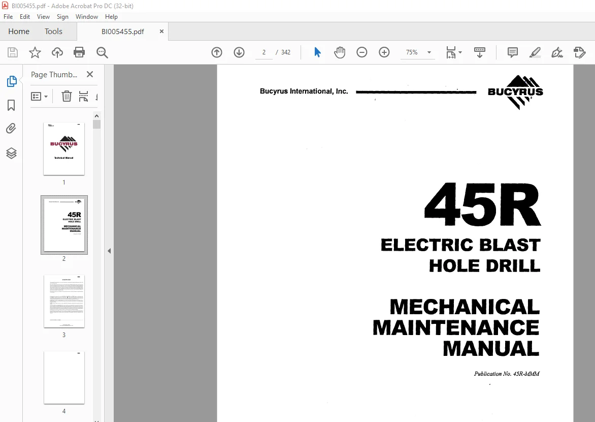
CAT Bucyrus 45R Electric Blast Hole Drill Mechanical Maintenance Manual BI005455 – PDF DOWNLOAD
$28.95
CAT Bucyrus 45R Electric Blast Hole Drill Mechanical Maintenance Manual BI005455 – PDF DOWNLOAD
Description
CAT Bucyrus 45R Electric Blast Hole Drill Mechanical Maintenance Manual BI005455 – PDF DOWNLOAD
FILE DETAILS:
CAT Bucyrus 45R Electric Blast Hole Drill Mechanical Maintenance Manual BI005455 – PDF DOWNLOAD
Language : English
Pages : 342
Downloadable : Yes
File Type : PDF
DESCRIPTION:
CAT Bucyrus 45R Electric Blast Hole Drill Mechanical Maintenance Manual BI005455 – PDF DOWNLOAD
FOREWORD:
- The purpose of this manual is to provide information concerning the general maintenance of
the 45-R rotary blast hole drill. - The -45-R consists of three major units, the lower works, the mainframe and the mast. The lower
works provides a foundation for the mainframe and contains a portion of the equipment necessary to
propel the drill. The mainframe includes the hydraulic, main air and auxiliary air systems, the
hoist-propel trans mission and the machinery house. The machinery house encloses the majority of
the mechanical equip ment necessary for the main and auxiliary air systems, the
hydraulic systems and electrical control systems. The machinery house is pressurized with
filtered air to minimize dirt and heat build-up. The operator’s cab, mounted to the mainframe,
provides the operator’s station, and enclosed the majority of the controls necessary to operate
the drill. - This manual consists of six chapters, each divided into sections. A table of contents is located
in the front of the manual. - Throughout this manual the words CAUTION, WARNING and NOTE appear in bold face type.
CAUTION is preceded by the safety alert symbol and indicates that injury to
personnel could occur if the proper procedures are not followed during operation or
maintenance. Always read the CAUTION note carefully and use extreme care while performing that
particular function. - WARNING indicates a possible hazard to the machine or its components if the proper procedures are
not followed. Whenever the word WARNING appears, special attention should be given to prevent
possible equipment damage. - NOTE is used to stress a point or to give additional information concerning the procedure
being dis cussed. - TheseCAUTION’s and WARNING’s are not all-inclusive. Itis impossible for Bucyrus-Erie Company to
know, evaluate, and advise maintenance and service personnel in every conceivable way a
service operation might be performed and of the resulting possible hazardous consequences of
each method. It is therefore extremely important that anyone who uses a service procedure or tool
which is not recommended by Bucyrus-Erie Company to first satisfy himself that the service
procedure or tool he chooses will not jeopardize his own safety, the safety of others, or cause
machine or component damage. - Every effort has been made to make this manual as complete and accurate as possible at
the time of publication. Bucyrus-Erie Company, however, reserves the right to continually improve
its products. For this reason changes may have been made to the machine or its equipment that are
notdetailed in this manual.
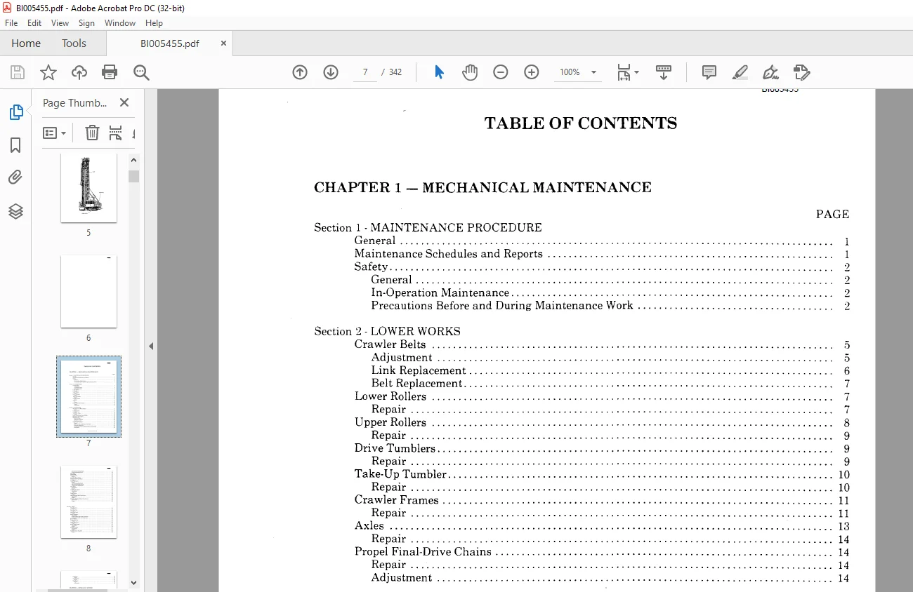
TABLE OF CONTENTS:
CAT Bucyrus 45R Electric Blast Hole Drill Mechanical Maintenance Manual BI005455 – PDF DOWNLOAD
CHAPTER 1 – MECHANICAL MAINTENANCE
PAGE
Section 1 – MAINTENANCE PROCEDURE
General 1
Maintenance Schedules and Reports 1
Safety 2
General 2
In-Operation Maintenance 2
Precautions Before and During Maintenance Work 2
Section 2 – LOWER WORKS
Crawler Belts 😉
Adjustment 5
Link Replacement 6
Belt Replacement 7
Lower Rollers 7
Repair 7
Upper Rollers 8
Repair 9
Drive Tumblers 9
Repair 9
Take-Up Tumbler 1
Repair 1
Cra\vler Frames 11
Repair 11
Axles 13
Repair 14
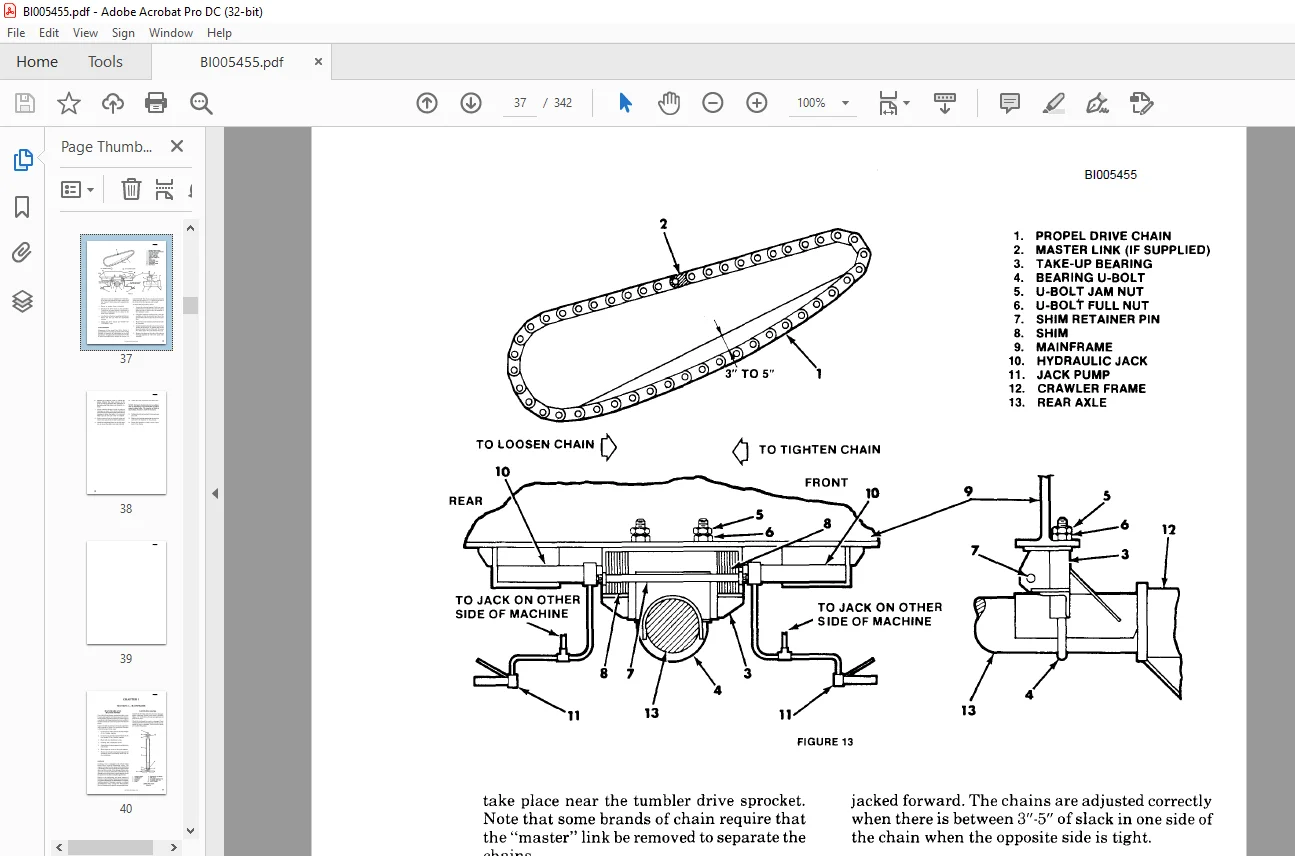
Propel Final-Drive Chains 14
Repair 14
Adjustment 14
Section 3 – MAINFRAME
Mainframe and Mast Support 17
Repair 17
Leveling Jacks 17
Repair 18
Machinery House 19
Repair 19
House Ventilation Fan and Filter 19
Walkways and Ladders 19
Operator s Cab 19
Operator s Seat 2
Operator s Controls 29
Ventilation Unit 2
Hoist-Propel Gearcase 2
Repair 2
Removal and Installation of Gearcase 21
Gearcase Suspension 22
Hoist-Propel Gearcase Disassembly and Assembly 23
Hoist Shaft 23
BUCYRUS-ERIE COMPANY 1983
BI 5455
Second Intermediate Shaft 25
First Intermediate Shaft 26
Idler Shaft 26
Propel Shaft 27
Propel Clutches 28
Repair 28
Hydraulic Motor Shaft 29
Electric Hoist-Propel Motor 3
Repair 3
Propel Machinery 31
Repair 31
First Intermediate Shaft 31
Second Intermediate Shaft 32
Propel Chain Adjustment 33
Hoist Brake 33
Adjustment 34
Repair 36
Auxiliary Reel Brake 37
Adjustment 37
Repair 38
Propel Brakes 39
Repair 4
Hoist-Auxiliary Reel Clutch Lever 4
Adjustment 41
Repair 41
Hydraulic Pulldown Motor Clutch Lever 42
Adjustment 42
Repair 43
Section 4 -MAST
Mast Structure 45
Repair 45
Mast Lock Pins 46
Repair 46
Mast Lock Latch 47
Repair 47
Rotary Gearcase 47
Adjustment 5
Repair (earlier style rotary gearcase) 51
Repair (latest style rotary gearcase) 52
Rotary Motor 54
Rotary Coupling 55
Repair 55
Rotary Shock Sub 56
Repair 56
Rotary Guide Frame 57
Adjustment 58
Repair 59
Pulldown Chains 61
Adjustment 61
Repair 61
Pulldown Chain Equalizer 63
Repair 63
BI 5455
Tool Racks 65
Repair 65
Tool Wrenches 67
Repair 68
Back Braces 68
Repair 68
Adjustment 68
CHAPTER 2 – HYDRAULIC SYSTEM
Section 1- SYSTEM OPERATION 71
Section 2 -GENERAL MAINTENANCE 75
Hydraulic System Cleanliness 75
Oil Requirements 75
Oil and Filter Changes 75
Weekly Maintenance Checks 76
Oil Reservoir Repairs 76
Unloader Valve Adjustment 77
Pressure Regulating (RelieD Valve Adjustment 77
Chain Equalizer Valve Adjustment 77
Section 3 -COMPONENT MAINTENANCE
Hydraulic Pump Overhaul 79
Disassembly 79
Cleaning 79
Inspection 79
Reassembly 8
Test Procedure 81
Main Valve Banks : 81
General 81
Disassembly 81
Cleaning Inspection and Repair 83
Assembly 83
Hydraulic Pulldown Motor 83
Disassembly 83
Cleaning Inspection and Repair 85
Reassembly 85
Disassembly of Chain Equalizer Valve 85
Hydraulic Oil Cooler 86
Weekly Maintenance Check 86
1 Hour Maintenance Check 86
Yearly Maintenance Check 86
CHAPTER 3 – AIR SYSTEMS
Section 1 – SYSTEMS OPERATION
General 87
Main Air System 87
Auxiliary Air System 87
Safety 87
BUCYRUS·ERIE COMPANY 1983
BI 5455
Section 2 – GENERAL MAINTENANCE
Main Air System 91
General 91
Intake Air Filter· Box Type 91
Intake Air Filter· Tubular Type 91
Filter Replacement 92
Drive Belts 92
Belt Adjustment 92
Compressor Lubricator (Vane Compressor Only) 92
Feed Rate 93
Viscosity Grade 93
Lubricator Daily Maintenance Check 94
Lubricator Weekly Maintenance Check 94
Lubricator Service 94
Lubricator Priming 94
Compressor Radiator 94
Safety Valve Settings 94
Drill Pressure 95
Auxiliary Air System 95
Auxiliary Air Compressor 95
Miscellaneous Components 96
Unloader Check Valve Service 96
Tanner De-icer (optional) 96
Air Tanks 97
Air Tank Valves 97
Pressure Switch 97
Filter 97
Anti-Freezer 97
Maintenance Procedure for Air Dryer 98
Desiccant Canister Removal 98
Purge Valve Removal 99
Section 3 – AUXILIARY AIR COMPRESSOR (KELLOGG-AMERICAN)
Disassembly of Pump 1 1
Fitting and Reassembling 1 2
Section 4 – MAIN AIR COMPRESSOR
Rotary Vane Compressor (Allis-Chalmers) 1 5
1 Hour Maintenance Check 1 5
4 Hour Maintenance check 1 6
Blade Protection in Idle Units 1 9
Rotor Alignment for Redoweling 11
Rotor Field Redoweling 11
Rotary Screw Compressor (Allis-Chalmers) III
Description 111
Coupling Alignment 112
Start-Up Procedure 113
Controls and Instruments 114
Lubrication System 119
Air Filters 126
Maintenance Schedule 127
BI 5455
BI 5455
CHAPTER 4 – DUST CONTROL
Section 1 -GENERAL MAINTENANCE
Drilling Platforms and Dust Curtains 133
Filter Air-Bag System (Amerpulse~) 133
Daily Maintenance Checks 133
Monthly Maintenance Checks 133
Six Month Maintenance Checks 134
Water Injection (using water pump) 134
Water Injection (pressurized) 134
Cold Weather Protection System 135
Section 2 – MAINTENANCE OF AMERPULSE!
Operating Principles 137
Filter Tube Installation 137
Printed Circuit Timer Test 137
Solenoid Valve Test 139
Pulse Recommendations 139
Hopper Vibrator 139
CHAPTER 5 – LUBRICATION
Section 1- LUBRICATION PROCEDURES
General 141
Lubricant Cleanliness 141
Automatic System Lubrication Points 141
Manual Lubrication Points 141
Lubricant Benchmarks 142
Lubrication Charts 142
Gearcase and Reservoir Capacities 142
Lower Works 143
Mainframe (Part 1) 144
Mainframe (Part 2) 145
Mast (Part 1) 146
Mast (Part 2) 147
Mast (Part 3) 148
Section 2 – LINCOLN AUTOMATIC SYSTEM
Troubleshooting Systems 149
Air Locks 149
Dirty Supply Lines 149
All Injectors Do Not Function Properly 149
After Venting the Indicator Stems on the Injectors
Do Not Return to Their Normal Position 149
Failure of Pump to Build Up Pressure 15
Sluggish Pump Operation 15
Slow Pressure Rise 15
Assembly of Tubing Compression Fittings 15
Principle of Operation – Pump Air Motor 15
Service of Lower Pumping Unit 152
Lubrication 153
Installation Operating and Maintenance Instructions 153
© BUCYRUS-ERIE COMPANY 1983
BI 5455
BI 5455
Section 3 -TRABON AUTOMATIC SYSTEM
Locating Blockage in System 157
Terminology 157
Procedure 157
Torque Information in Foot Pounds 16
Section 4 VANE TYPE MAIN COMPRESSOR LUBRICATOR OR BIT LUBRICATION
Operation and Adjustment 161
To Start Lubricator 161
To Adjust Lubricator 161
Sight Feed Unit 161
Purging Oil From Pumping Unit 161
Care of Lubricator 162
CHAPTER 6 – TROUBLESHOOTING
Section 1 -TROUBLESHOOTING
General 163
Drilling 164
Rotary Drive Unit 166
Hoist-Propel Tr~nsmission 166
Mast 167
Main Air Compressor (vane type) 167
Main Air Compressor (screw type) 17
Auxiliary Air Compressor 173
Hydraulic System 174
Hydraulic Oil Cooler 175
Hydraulic Cylinder 175
Hydraulic Pump 176
Hydraulic Pulldown Motor 178
Pressure Regulating and Pulldown Pressure Relief Valves 179
Hydraulic Chain Equalizer Pump 18
Control Valves 18
Unloader Valves 181
Amerpulse® 182
APPENDICES
Appendix Al -GEAR INSPECTION 1A
Appendix A2 – BOLT TORQUING
Bolt Torque Values for Static Joints Bulletin 6-82-1
Appendix A3 – PINION AND COUPLING INSTALLATION
Removal For Motor Shaft 3A
Mounting Pinion or Coupling Shaft 3A
Appendix A4 – LUBE BENCHMARKS
Multipurpose Type Grease (MPG) 5A
Air Compressor (vane type) Lubricant (ACVL) 6A
BI 5455
BI 5455
Air Compressor (piston type) Lubricant (ACPL) 7A
Chain Drive Lubricant (CDL) 8A
Drill Pipe Thread Lubricant (DPTL) o 9A
Multipurpose Oil (MPO) lOA
Open Gear Lubricant (OGL) lOA
Regular Type Gear Lubricant (RGL) o 12A
Running Wire Rope Lubricant (RWRL) o16A
Hydraulic Oil for Mining Machinery (HYDO) 17A
Appendix A5 -RECOMMENDED PROCEDURES FOR MAINTENANCE WELDING OF PRINCIPAL
STRUCTURES ON BLAST HOLE DRILLS
General o o o o o19A
Maintenance Welding 19A
Structural Materials 19A
Welding Electrodes 2 A
Preheat Requirements o o 22A
Removal of Cracks 22A
Weld Groove Preparation o o o 22A
Drill Pipe Welding 22A
Welding Technique o o o o o o 23A
Weld Inspection 23A
Repair of Broken Parts 23A
Methods of Repair of Cracks 23A
Appendix A6 – PREVENTIVE MAINTENANCE CHECKLISTS
Level I Inspection 25A
Level II Inspection 3 A
Level III Inspection 32A
Appendix A7 – SPECIAL DRAWINGS
Hoist-Pulldown Shaft o33A
Propel Shaft 33A
Idler Shaft 33A
Hydraulic Motor Shaft o34A
Second Intermediate Pulldown Shaft 34A
First Intermediate Pulldown Shaft 34A
First Intermediate Propel Shaft o35A
RH and LH Intermediate Propel Shafts 35A
Rotary Gearcase Shafts – Early Style 36A
Rotary Gearcase Shafts – Latest Style 36A
Rotary Unit Shipper Shaft 37A
Drive Tumbler Shaft 37A
BUCYRUS-ERIE COMPANY 1983
IMAGES PREVIEW OF THE MANUAL:
Questions? Email us: [email protected]
PLEASE NOTE:
- This is the same manual used by the dealers to diagnose and troubleshoot your vehicle
- You will be directed to the download page as soon as the purchase is completed. The whole payment and downloading process will take anywhere between 2-5 minutes
- Need any other service / repair / parts manual, please feel free to contact [email protected] . We still have 50,000 manuals unlisted
S.V