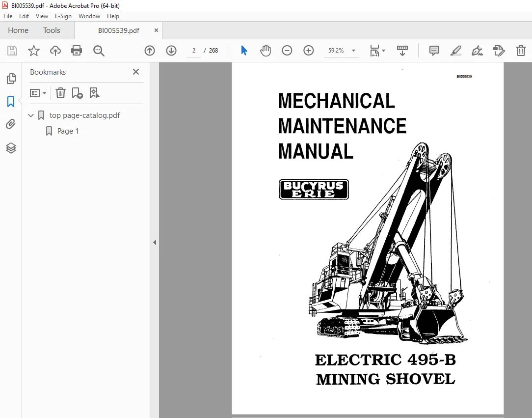
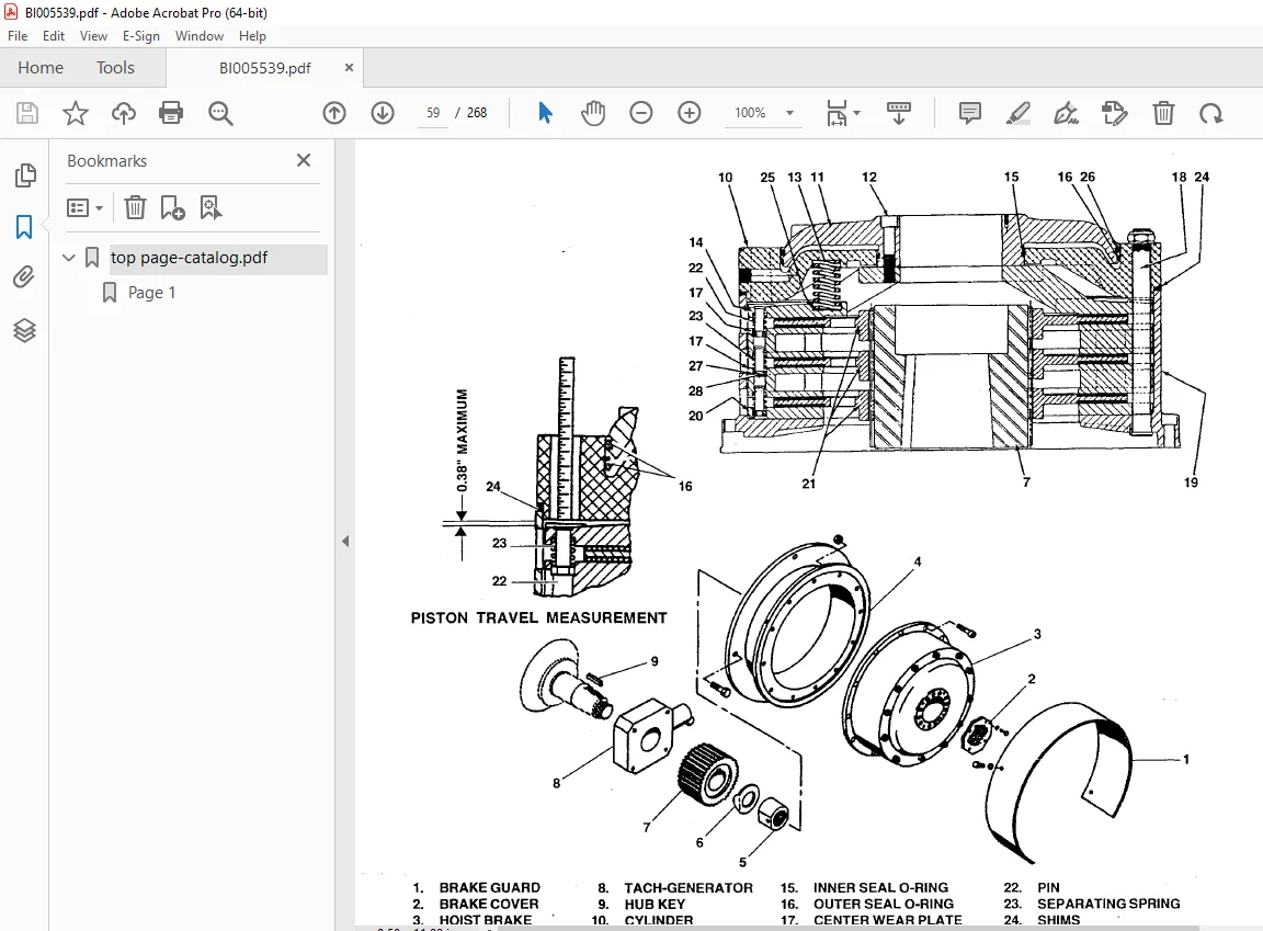
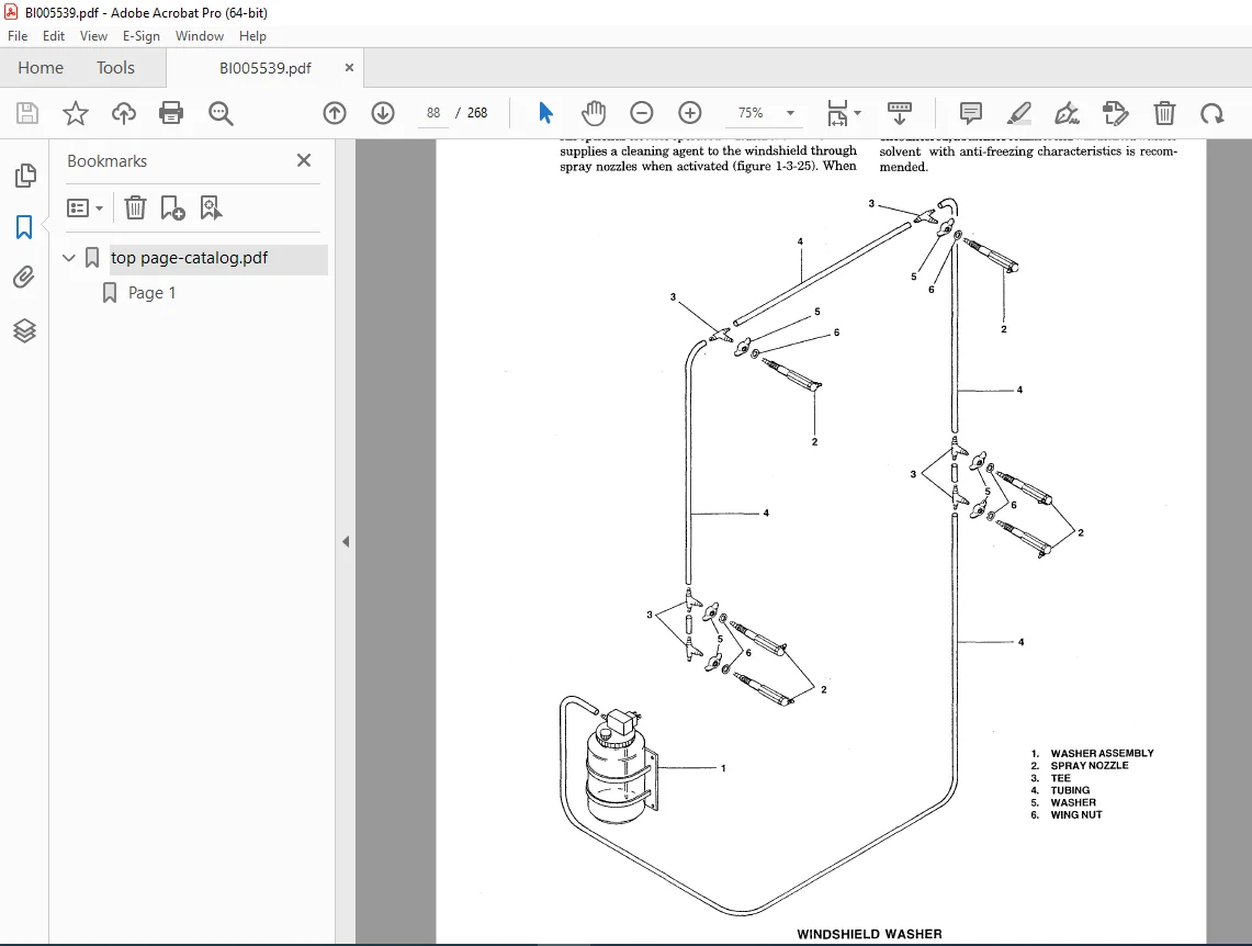
CAT Bucyrus 495-B Electric Mining Shovel Mechanical Maintenance Manual BI005539 PDF DOWNLOAD
$27.95
CAT Bucyrus 495-B Electric Mining Shovel Mechanical Maintenance Manual BI005539 PDF DOWNLOAD
Description
CAT Bucyrus 495-B Electric Mining Shovel Mechanical Maintenance Manual BI005539 PDF DOWNLOAD
FILE DETAILS:
CAT Bucyrus 495-B Electric Mining Shovel Mechanical Maintenance Manual BI005539 PDF DOWNLOAD
Language : English
Pages : 268
Downloadable : Yes
File Type : PDF
IMAGES PREVIEW OF THE MANUAL:
TABLE OF CONTENTS:
CAT Bucyrus 495-B Electric Mining Shovel Mechanical Maintenance Manual BI005539 PDF DOWNLOAD
CHAPTER 1 MECHANICAL MAINTENANCE
SECTION 1 – MAINTENANCE PROCEDURE
GENERAL 1-1-1
MAINTENANCE SCHEDULES AND REPORTS 1-1-1
SAFETY : 1-1-2
General 1-1-2
In-Operation Maintenance 1-1-2
Precautions Before and During Maintenance Work 1-1-2
SECTION 2 – LOWER WORKS
CRAWLER BELTS 1-2-1
Inspection 1-2-1
Adjustment 1-2-2
Link Replacement 1-2-3
Belt Replacement 1-2-3
Optional Link Bushing Replacement 1-2-4
TAKE-UP TUMBLER 1-2-4
UPPER ROLLERS 1-2-6
LOWER ROLLERS 1-2-6
DRIVE TUMBLER 1-2-7
TUMBLER DRIVE SHAFT 1-2-7
PROPEL BRAKE 1-2-10
PROPEL MACHINERy 1-2-14
PLANETARY GEARCASE 1-2-15
PROPEL MOTOR BLOWER AND DUCTS 1-2-18
CRAWLER FRAMES AND TRUCK FRAME 1-2-18
SWING RACK 1-2-19
ROLLER CIRCLE 1-2-20
CENTER PINTLE 1-2-21
COLLECTOR RINGS 1-2-24
CABLE REEL (OptionaD 1-2-26
SECTION 3 – ROTATING DECK
REVOLVING FRAME 1-3-1
DECK MACHINERY 1-3-2
HOIST MACHINERY 1-3-2
Gear Train 1-3-2
Hoist Gear and Drum 1-3-4
Hoist Brake (for machines through sIT). 140981, except 140987) 1-3-6
Hoist Brake (for machines sIn 140987, 140993 and up) 1-3-9
Hoist Limit Switch 1-3-13
Hoist Motor 1-3-13
CROWD MACHINERY 1-3-14
Gear Train 1-3-14
Crowd Motor 1-3-17
Crowd Brake 1-3-20
Crowd Gear and Drum 1-3-23
Crowd and Retract Limit Switch 1-3-25
SWING MACHINERY 1-3-25
Gear Train 1-3-25
Swing Motor 1-3-31
Swing Brake 1-3-31
BI005539
MACHINERY HOUSE 1-3-35
HOUSE FANS 1-3-36
DYNAVANE AIR CLEANER 1-3-36
WALKWAYS 1-3-37
OPERATOR’S CAB 1-3-37
Seat 1-3-37
Windshield Wipers 1-3-38
Windshield Washer 1-3-39
TYPICAL RETRACTABLE BOARDING LADDER (Optional) 1-3-40
TYPICAL RETRACTABLE BOARDING STAIR
(Optional – for machines through sin 140988, except 140987) 1-3-41
TYPICAL RETRACTABLE BOARDING STAIR
(Optional – for machines sIn 140987 and up) 1-3-42
SECTION 4 – FRONT END EQUIPMENT
BOOM 1-4-1
Boom Limit Switch 1-4-1
Boom Point Sheaves 1-4-2
Boom Bumpers 1-4-3
Saddle Block 1-4-3
DIPPER HANDLE 1-4-4
Dipper Handle Removal 1-4-4
Retract Take-Up Mechanism Removal 1-4-5
Front Stop & Spreader Removal 1-4-7
Crowd Cushion (with Pre-Assembled Cushion Stack) 1-4-7
DIPPER 1-4-9
Dipper Padlock 1-4-11
DIPPER TRIP DIS ASSEMBLY1-4-14
A-FRAME 1-4-14
AUXILIARY WINCH (Optional) 1-4-16
HOIST ROPE SUPPORT ROLLER (Optional) 1-4-16
BOOM STRUCTURAL STANDS 1-4-16
WIRE RUNNING ROPES 1-4-17
Inspection 1-4-17
Hoist Rope Reeving 1-4-17
Retract Rope Reeving (for machines through sIn 140993) 1-4-20
Retract Rope Reeving (for machines sIn 140999 and up) 1-4-22
Crowd Rope Replacement (for machines through sIn 140993) 1-4-23
Crowd Rope Replacement (for machines sIn 140999 and up) 1-4-25
Dipper Trip Rope Reeving 1-4-26
CHAPTER 2 AIR SYSTEM
SECTION 1 – GENERAL MAINTENANCE
SAFETY 2-1-1
GENERAL 2-1-1
AIR COMPRESSOR (Quincy QSB20) 2-1-5
AIR LINES 2-1-5
AIR TANK 2-1-5
AIR LINE LUBRICATOR 2-1-5
AIR LINE FILTER 2-1-5
AIR LINE REGULATOR 2-1-6
TANNER DE-ICER (Optional) 2-1-6
AIR/LUBE SWIVEL ASSEMBLY 2-1-6
PRESSURE SWITCHES 2-1-6
SOLENOID VALVES 2-1-6
BI005539
SECTION 2 – COMPONENT MAINTENANCE
AIR COMPRESSOR (Quincy QSB20) 2-2-1.
General Description 2-2-1
Principles of Compressor Operation 2-2-1
Description of Air Flow 2-2-2
Description of Oil Flow and Compressor Cooling System 2-2-2
Description of the Air/Oil Reservoir and Air/Oil Separator Element 2-2-3
Description of Compressor Control System 2-2-3
High Temperature Switch 2-2-3
Indicators 2-2-4
COMPRESSOR OPERATION 2-2-4
Before Starting 2-2-4
Starting the Compressor 2-2-5
Stopping the Compressor 2-2-5
PREPARING FOR MAINTENANCE OR SERVICE 2-2-5
SERVICING 2-2-5
Safety 2-2-5
Lubrication 2-2-6
Compressor Oil Filter 2-2-6
Compressor Air/Oil Separator Elements 2-2-6
Oil Scavenging System 2-2-7
Air Filter 2-2-7
Control Line Air Filter 2-2-7
ASSEMBLY AND DISASSEMBLY OF COMMON WEARING PARTS 2-2-7
Compressor Shaft Oil Seal 2-2-7
DRIVE BELT REPLACEMENT 2-2-9
AIR/LUBE SWIVEL ASSEMBLY REMOVAL 2-2-10
AIR DRYER (Salem 975-109) (Optional) 2-2-12
Description 2-2-12
Operation 2-2-12
Maintenance 2-2-14
Repair 2-2-16
Regenerating Orifice 2-2-16
Canister Removal 2-2-16
Canister Compactor 2-2-17
Desiccant Charge Renewal 2-2-17
Inlet Check Valve 2-2-19
Pre-Coalescer Element 2-2-19
Drain Valve 2-2-20
Outlet Check Valve 2-2-20
Solenoid Assembly 2-2-20
PRESSURE SWITCH ASSEMBLY, TIMER & CIRCUIT BOARD ASSEMBLY .. 2-2-22
Timer & Circuit Board 2-2-22
Pressure Switch 2-2-22
Purge Valve 2-2-23
CHAPTER 3 LUBRICATION
SECTION 1 – GENERAL LUBRICATION
LOWER WORKS 3-1-2
ROTATING DECK 3-1-2
FRONT END 3-1-::-
LUBRICATION BENCHMARKS 3-1-3 ‘
BI005539
SECTION 2 – AUTOMATIC LUBRICATION SYSTEMS
INSPECTION 3-2-1
LUBE SYSTEM 3-2-1
AIR PUMP SERVICE 3-2-2
LINES AND CONTROL SERVICE 3-2-2
INJECTORS AND SPRAY NOZZLES 3-2-3
Startup of Automatic Lubrication Systems 3-2-4
CHAPTER 4 TROUBLESHOOTING
SECTION 1 – LOWER WORKS
CRAWLER 4-1-1
PROPEL MOTOR COUPLING 4-1-5
PROPEL BRAKE 4-1-6
PROPEL MOTOR and BLOWER 4-1-6
SWING RACK TEETH 4-1-6
HOUSE ROLLER RAILS 4-1-7
HOUSE ROLLERS 4-1-7
CENTER PINTLE 4-1-9
SECTION 2 – ROTATING DECK
HOIST MACHINERY 4-2-1
HOIST MOTOR PINION SHAFT 4-2-1
HOIST INTERMEDIATE SHAFT ASSEMBLY 4-2-2
.HOIST DRUM ASSEMBLY 4-2-3
HOIST BRAKE 4..:2-5
CROWD MACHINERY 4-2-5
CROWD DRUM GEAR AND PINION LUBRICATION 4-2-7
CROWD BRAKE 4-2-8
A-FRAME 4-2-9
SWING MACHINERY 4-2-10
SWING BRAKE 4-2-12
SECTION 3 – FRONT END EQUIPMENT
BOOM 4-3-1
DIPPER – PIN CONNECTED 4-3-4
DIPPER DOOR SNUBBERS 4-3-5
DIPPER HANDLE 4-3-5
AIR/LUBE SWIVEL 4-3-7
SECTION 4 – AIR SYSTEM
QUINCY QSB 20 SCREW COMPRESSOR 4-4-1
APPENDICES
APPENDIX Al – GEAR INSPECTION
APPENDIX A2 – BOLT TORQUING
TORQUE WRENCH METHOD A2-1
TURN-OF-THE-NUT METHOD A2-2
APPENDIX A3 – MAINTENANCE WELDING
PRINCIPAL STRUCTURES A3-I
General A3-1
Maintenance Welding A3-1
Structural Material A3-2
Welding Electrodes A3-2
BI005539
Preheat Requirements A3-5
Removal of Cracks A3-6
Weld Groove Preparation A3-6
Butter Welding A3-6
Welding Technique A3-6
Weld Inspection A3-6
Repair of Broken Parts A3-8
DIPPER HANDLES A3-8
Maintenance Welding A3-8
Flame Straightening Bent Tube A3-8
Welding Tube Without Backing Ring A3-10
Welding Tube Using Backing Ring A3-13
Handle End Casting Replacement A3-14
Tube Replacement A3-15
Stress Relieving Welded Tube , A3-15
REPAIR WELDING OF SWING RACKS A3-15
Crack Repair Welding A3-15
Broken Tooth Repair Welding A3-17
Swing Rack to Truck Frame Welding A3-19
APPENDIX A4 – PINION, BRAKE DRUM AND COUPLING INSTALLATION A4-1
APPENDIX A5 – PREVENTIVE MAINTENANCE CHECKLISTS A5-1
APPENDIX A6 – ROLLER REPLACEMENT A6-1
APPENDIX A7 – BRAKE OR CLUTCH MAINTENANCE CHECKLIST A7-1
APPENDIX A8 – ROLLER CIRCLE REPAIR MODIFICATION A8-1
APPENDIX A9 – SHIMMING INSTRUCTIONS A9-1
APPENDIX AIO – DRIVE TUMBLER REBUILD PRo’CEDURE AIO-I
APPENDIX All- ELECTRIC MINING SHOVEL “BREAK-IN” INSTRUCTIONS All-1
APPENDIX Al2 – MOTOR COUPLING ALIGNMENT A12-1
APPENDIX Al3 – INSTALLATION GUIDELINES FOR DUO-CONE SEALS AI3-1
APPENDIX Al4 – TORQUING PROCEDURE FOR SUPERBOLT® TORQUE NUTS A14-1
APPENDIX Al5 – PIN LOCKING ASSEMBLIES A15-1
APPENDIX Al6 – TYPICAL GEARCASE FLANGE SEALING INSTRUCTIONS A16-
Questions? Email us: [email protected]
https://vimeo.com/856633575?share=copy
DESCRIPTION:
CAT Bucyrus 495-B Electric Mining Shovel Mechanical Maintenance Manual BI005539 PDF DOWNLOAD
FOREWORD:
The purpose of this manual is to provide information concerning the general maintenance of the 495-B electric mining shovel. The Model 495-B consists of three major units: the lower works, the rotating deck, and the front-end equipment. The lower works provide a foundation for the revolving frame and contain the necessary equipment to propel the shovel.
- The rotating deck includes the revolving frame, ballast box, and machinery house.
- The machinery house encloses all of the hoist, swing, and crowd machinery, and the electrical systems required to control machine functions.
- It also contains an air filtration system to minimize heat and dirt build-up in the machinery house. An elevated cab mounted on the house provides the machinery operator’s station.
- The cab contains all machine operating controls. The front-end equipment is comprised of the A-frame, dipper, dipper handle, boom, running ropes, and boom structural strands. This manual consists of four chapters, each divided into sections. A table of contents is located in the front of the manual.
- Throughout this manual, the words CAUTION, WARNING, and NOTE appear in bold face type. CAUTION is preceded by the safety alert symbol “A” and indicates that injury to personnel could occur if the proper procedures are not followed during operation or maintenance.
- Always read the CAUTION note carefully and use extreme care while performing that particular function. WARNING indicates a possible hazard to the machine or its components if the proper procedures are not followed.
- Whenever the word WARNING appears, special attention should be given to prevent possible equipment damage. NOTE is used to stress a point or to give additional information concerning the procedure being discussed. These CAUTIONs and WARNINGs are not all-inclusive.
- It is impossible for Bucyrus-Erie Company to know, evaluate, and advise maintenance and service personnel in every conceivable way a service operation might be performed and of the resulting possible hazardous consequences of each method.
- t is, therefore, extremely important that anyone who uses a service procedure or tool which is not recommended by Bucyrus-Erie Company first satisfy himself that the service procedure or tool he chooses will not jeopardize his own safety, the safety of others, or cause machine or component damage. Every effort has been made to make this manual as complete and accurate as possible at the time of publication.
- Bucyrus-Erie Company, however, reserves the right to continually improve its products. For this reason, changes may have been made to the machine or its equipment that are not detailed in this manual.
PLEASE NOTE:
- This is the same manual used by the dealers to diagnose and troubleshoot your vehicle
- You will be directed to the download page as soon as the purchase is completed. The whole payment and downloading process will take anywhere between 2-5 minutes
- Need any other service / repair / parts manual, please feel free to contact [email protected] . We still have 50,000 manuals unlisted
G.P