Description
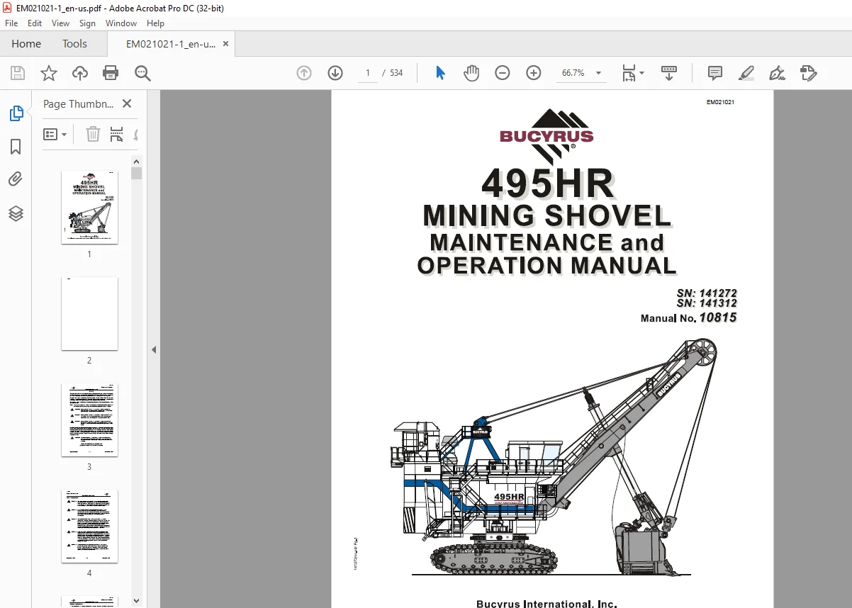
CAT BUCYRUS 495 HR MINING SHOVEL MAINTENANCE & OPERATION MANUAL EM021021 – PDF DOWNLOAD
FILE DETAILS:
CAT BUCYRUS 495 HR MINING SHOVEL MAINTENANCE & OPERATION MANUAL EM021021 – PDF DOWNLOAD
Language : English
Pages : 534
Downloadable : Yes
File Type : PDF
DESCRIPTION:
CAT BUCYRUS 495 HR MINING SHOVEL MAINTENANCE & OPERATION MANUAL EM021021 – PDF DOWNLOAD
SN: 141272
SN: 141312
Safety
The safety alert symbols displayed here and throughout this manual are used to call attention to instructions concerning personal safety. Carefully read and follow these instructions and observe all SAFETY, DANGER and CAUTION graphics mounted on various areas of the machine. Be certain that anyone servicing this machine is aware of these SAFETY SYMBOLS and their definitions. If it is impossible to safely perform any of the enclosed maintenance and operational procedures, contact your regional Bucyrus service representative or the factory. The following defines distinctions between safety instructions. In all these definitions the safety alert signal is used.
GENERAL PRECAUTIONS
• The employment of qualified maintenance personnel, through a scheduled maintenance
program, is the best way to minimize machine downtime and maximize productivity of
equipment.
• Keep hands, feet and clothing away from rotating parts.
• Wear a hard hat, safety shoes and protective lenses at all times.
• Replace any and all safety and warning placards if they are defaced or removed from the
machine.
• Think before you act. Carelessness is one luxury the service person cannot afford.
• Excessive or repeated skin contact with sealants or solvents may cause skin irritation. In
case of skin contact refer to the Material Safety Data Sheet (MSDS) for that material and the
suggested method of cleanup.
• Inspect safety catches (keepers) on all hoist hooks. Do not take a chance, the load could slip
off of the hook if they are not functioning properly.
• If a heavy item begins to fall, let it fall, don’t try to catch it.
• Keep your work area organized and clean. Wipe up oil or spills of any kind immediately. Keep
tools and parts off of the ground. Eliminate the possibility of a fall, slipping or tripping.
• Floors, walkways and stairways must be clean and dry. After fluid draining operations be sure
all spillage is cleaned up.
• Electrical cords and wet metal floors make a dangerous combination.
• Regularly inspect for any loose bolts or locking devices and properly secure them.
• Use extreme caution while working near any electrical lines or equipment whether it be high
or low voltage. Never attempt electrical repairs unless you are qualified.
• Check limit switches for proper operation.
• After servicing, be sure all tools, parts or servicing equipment are removed from the machine
and secured in an appropriate storage area.
• Mechanical Brakes are designed for use as static holding brakes only. Use as a motion
(dynamic) brake in emergency situations only.
• Use proper interior and exterior lighting.
• Install and maintain proper grounding and ground fault protection systems.
• Allow electrical inspection and maintenance to be performed only by a qualified electrician.
IMAGES PREVIEW OF THE MANUAL:


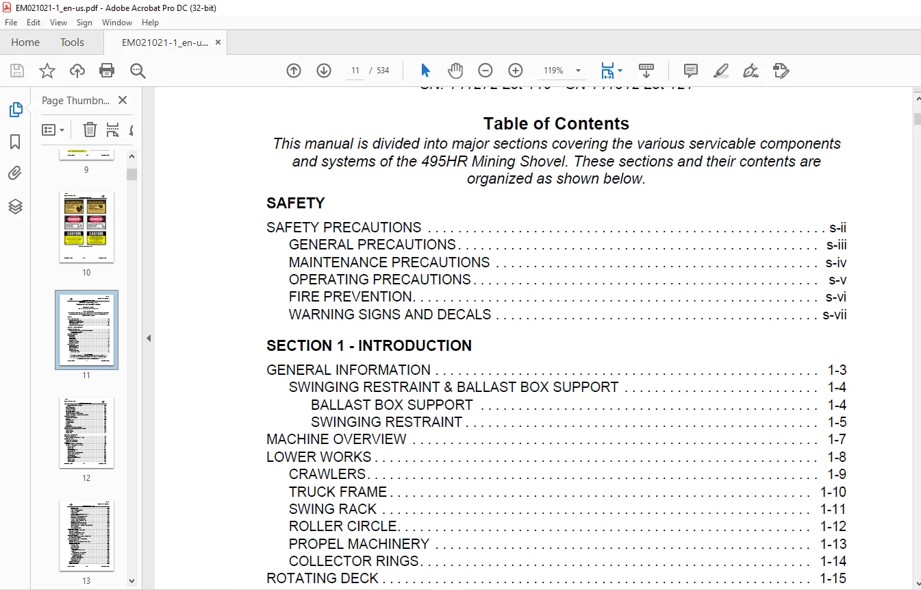
TABLE OF CONTENTS:
CAT BUCYRUS 495 HR MINING SHOVEL MAINTENANCE & OPERATION MANUAL EM021021 – PDF DOWNLOAD
Safety Precautions……………………………………………….. 4
General Precautions…………………………………………… 5
Maintenance Precautions……………………………………….. 6
Operating Precautions…………………………………………. 7
Fire Prevention………………………………………………. 8
Warning Signs And Decals………………………………………. 9
Introduction…………………………………………………….. 27
General Information………………………………………………. 27
SWINGING RESTRAINT & BALLAST BOX SUPPORT………………………… 28
Ballast Box Support……………………………………….. 28
Swinging Restraint………………………………………… 29
Machine Overview…………………………………………………. 31
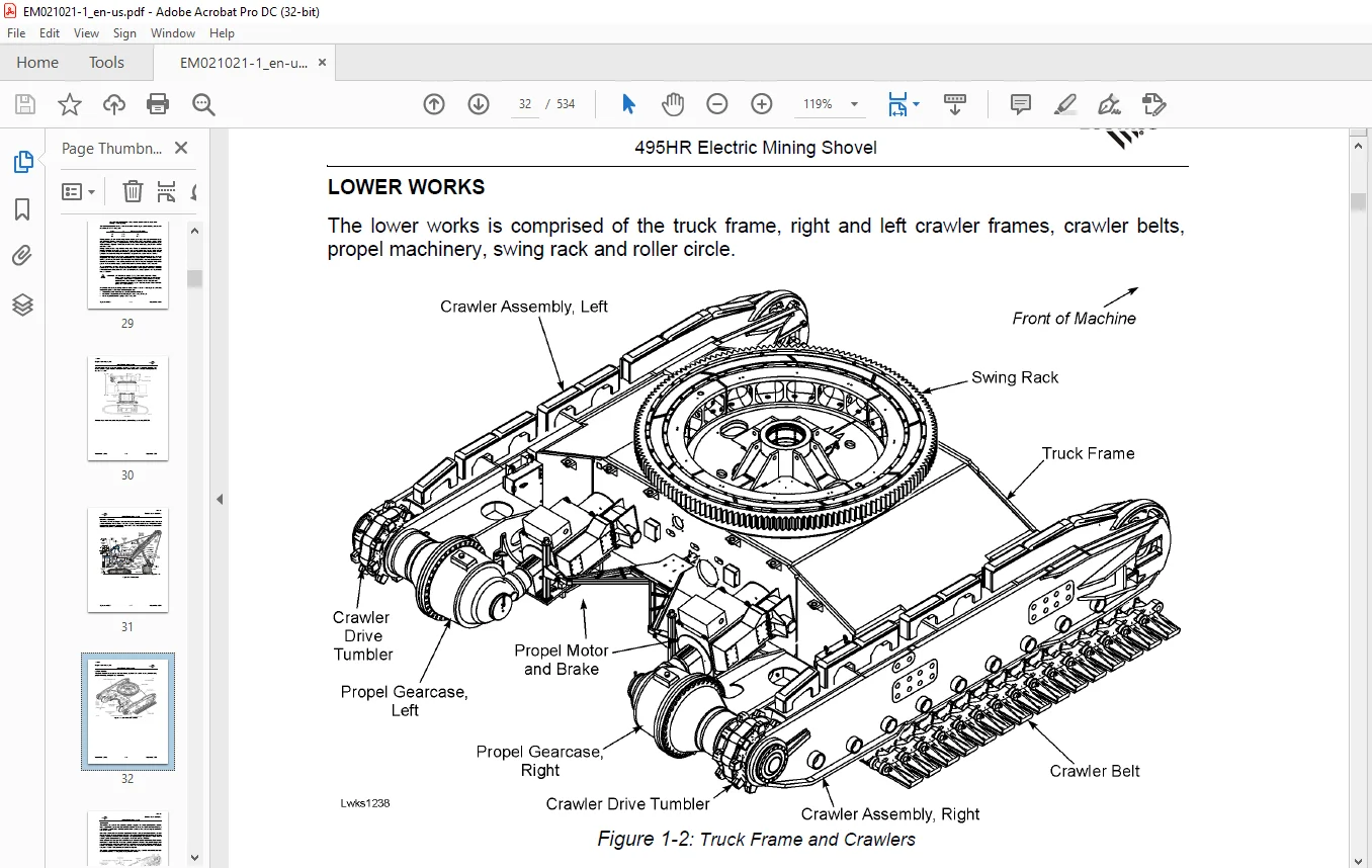
Lower Works……………………………………………………… 32
Crawlers…………………………………………………….. 33
Truck Frame………………………………………………….. 34
Swing Rack…………………………………………………… 35
Roller Circle………………………………………………… 36
Propel Machinery……………………………………………… 37
Collector Rings………………………………………………. 38
Rotating Deck……………………………………………………. 39
Revolving Frame………………………………………………. 39
Center Pintle………………………………………………… 39
Deck Extensions………………………………………………. 41
Ballast Box………………………………………………….. 41
Machinery House………………………………………………. 41
Boarding Stairs…………………………………………… 42
Vertical Boarding Ladder…………………………………… 43
A-Frame……………………………………………………… 44
Hoist Machinery………………………………………………. 45
Swing Machinery………………………………………………. 46
Crowd Machinery………………………………………………. 47
OPERATOR’S CAB……………………………………………….. 48
Compressed Air System…………………………………………. 49
Automatic Lubrication System…………………………………… 50
Lube Reservoir fill / Overflow Plumbing…………………………. 51
Front End Equipment………………………………………………. 52
Suspension Strands……………………………………………. 52
Boom………………………………………………………… 53
Running Ropes………………………………………………… 54
Saddle Block…………………………………………………. 55
Dipper Handle………………………………………………… 56
Dipper………………………………………………………. 57
Padlocks…………………………………………………….. 58
Dipper Trip………………………………………………….. 59
Typical Machine Specifications…………………………………….. 60
General Estimated Component Weights………………………………… 62
Lower Works………………………………………………….. 62
Upper Works………………………………………………….. 63
Front End……………………………………………………. 65
Operation……………………………………………………….. 71
General Information………………………………………………. 71
Operation Near Electrical Lines………………………………… 71
Operator’s Seat………………………………………………….. 73
Adjustable Armrest……………………………………………. 73
Adjustable Footrest…………………………………………… 74
Controls………………………………………………………… 75
Primary Operating Controls…………………………………….. 75
Controls On The Left Console…………………………………… 76
Left Joystick…………………………………………….. 77
Dipper Trip………………………………………………. 77
Signal Horn………………………………………………. 77
Start Pushbutton………………………………………….. 77
PLC Power On……………………………………………… 78
Drive Cabinet Temperature………………………………….. 78
Incomplete Sequence……………………………………….. 78
System Ready……………………………………………… 78
Phase Sequence……………………………………………. 78
Auxiliary Ground Fault…………………………………….. 78
Hoist Brake………………………………………………. 78
Crowd Brake………………………………………………. 78
Swing Brake………………………………………………. 78
Propel Brake……………………………………………… 78
Temperature………………………………………………. 78
HVAC System Control……………………………………….. 78
HVAC Fan Speed……………………………………………. 78
Cabin Lights……………………………………………… 78
Controls On The Right Console………………………………. 79
Right Joystick……………………………………………. 80
Emergency Stop Pushbutton………………………………….. 81
Windshield Wiper Switches………………………………….. 81
Control Stop Pushbutton……………………………………. 81
Control Reset Pushbutton…………………………………… 81
Air Compressor……………………………………………. 82
Dig/propel Transfer Switch…………………………………. 82
Main Power Off Pushbutton………………………………….. 82
Earth Continuity Lockout Pushbutton…………………………. 82
Seat Position…………………………………………….. 82
Radio/cassette/cd…………………………………………. 83
Operator’s Display……………………………………………….. 83
Display Area and Indicators……………………………………. 84
Display Screens………………………………………………. 84
Lubrication Control Panel……………………………………… 92
Fire Suppression System……………………………………….. 92
Pre-start Checks…………………………………………………. 92
Walk-around Ground Level Inspection…………………………….. 93
On-board Inspection…………………………………………… 95
Start-up, Operation And Shutdown…………………………………… 96
Machine Start-up……………………………………………… 96
Restarting After An Electrical Fault……………………………. 97
Machine Operation…………………………………………….. 97
Machinery Motions…………………………………………….. 98
Hoist Motion……………………………………………… 98
Crowd Motion……………………………………………… 99
Propel Motion……………………………………………..100
Swing Motion………………………………………………101
Proper Swing Motion…………………………………….102
Steering………………………………………………….103
Counter-rotation Turns………………………………….105
Positioning the Machine…………………………………….106
Back-up Method…………………………………………106
Drive-by Method………………………………………..107
Start Of The Dig Cycle……………………………………..108
Engaging The Bank………………………………………….111
Slope Limitations………………………………………….113
Excavated Material…………………………………………….115
Operation Checks………………………………………………115
Operating Hints……………………………………………….116
Stopping the Machine…………………………………………..117
Shutdown……………………………………………………..117
Lubrication………………………………………………………121
Lubrication Principles…………………………………………….121
Greasing Main A.C. Drive Motors…………………………………….122
1. Type of Grease……………………………………………..122
2. Initial Commissioning……………………………………….122
3. Maintenance………………………………………………..122
4. Regreasing Intervals………………………………………..123
Lubricant Selection……………………………………………….123
Oil Fill Capacities……………………………………………….125
Types Of Lubricants And Capacities Guidelines…………………….125
Quantities for First Fill of Lubricants………………………125
Automatic Lubrication System……………………………………….126
Lube Room…………………………………………………….127
Lube Reservoir fill / Overflow Plumbing………………………….128
Auto Lube Control Panel…………………………………….129
Lower Works Lubrication………………………………………..129
Propel Machinery Lubrication……………………………………130
Lubricant Replacement/sampling………………………………131
Lubricant Change Cycle………………………………….131
Revolving Frame Lubrication…………………………………….132
Hoist Machinery Lubrication…………………………………….133
Hoist Oil Cooler…………………………………………..134
Filter Element Cleaning…………………………………….137
Hoist Rope Rollers Lubrication………………………………….138
Oil Pump………………………………………………….139
Crowd Machinery Lubrication…………………………………….140
Swing Machinery Lubrication…………………………………….141
Air Compressor Lubrication……………………………………..142
Crowd Rope Take-Up Mechanism Lubrication…………………………143
Front End Lubrication………………………………………….143
Lincoln Type SL-1 Lubricant Injectors……………………………145
SL-1 Lubricant Injector Operation……………………………147
Injector Advantages………………………………………..149
Air Compressor Lubricant……………………………………….149
MPO – Multipurpose OIL…………………………………………150
RWRL – Running Wire Rope Lubricant………………………………151
EGL – Enclosed Gearcase Lubricant……………………………….152
MPG – Multipurpose Grease………………………………………155
OGL – Open Gear Lubricant………………………………………159
Certified Lubricants Listing……………………………………163
Preventive Maintenance…………………………………………….171
Introduction……………………………………………………..171
Preventive Maintenance Program………………………………….171
Elements of an Effective Maintenance Program……………………..172
Scheduled Preventive Maintenance Program…………………………173
General Safety Considerations…………………………………..173
Maintenance During Machine Operation………………………………..174
Maintenance Precautions………………………………………..175
Preventive Maintenance for Lubrication………………………………176
Lubricant Cleanliness………………………………………….177
Frequency of Inspection and Maintenance……………………………..178
Maintenance Schedules……………………………………………..178
Maintenance Inspection Check Points……………………………..178
Daily…………………………………………………….179
Every 100 Hours or Weekly…………………………………..182
Every 500 Hours Or Monthly………………………………….183
Every 1250 Hours or Quarterly……………………………….186
Every 2500 Hours or Semi-Annually……………………………189
5000 Hours or Annually……………………………………..191
Major Component Locations………………………………………….193
Service Procedures………………………………………………..221
Lower Works………………………………………………………221
Truck Frame Assembly…………………………………………..221
Swing Rack Assembly……………………………………………222
Roller Circle Rail Replacement – Lower……………………….222
Roller Circle Rail Replacement – Upper……………………….223
Roller Circle Assembly…………………………………………225
Roller Circle Adjustment……………………………………227
Adjustment Procedure……………………………………….227
Run-in Procedure for the Roller Circle……………………….227
Roller Circle Segment Removal……………………………….228
Roller Circle – Roller Replacement…………………………..229
Crawler Belts…………………………………………………….230
Crawler Belt Maintenance……………………………………….230
Crawler Belt Tension Adjustment……………………………..231
Crawler Shoe Replacement……………………………………233
Crawler Belt Replacement……………………………………234
Crawler Side Frame Assembly…………………………………….235
Crawler Side Frame Maintenance………………………………236
Slide Bar Replacement………………………………………237
Crawler Front Idler Roller Assembly………………………….238
Load and Idler Rollers……………………………………..241
Roller Removal or Replacement……………………………241
Propel Assembly…………………………………………………..244
Installation Notes…………………………………………….246
Main Propel Drive Shaft Removal…………………………………247
Main Propel Shaft – Disassembly……………………………..250
Tumbler Rebuild Procedure…………………………………..251
Propel Machinery………………………………………………253
Propel Gearcase Removal…………………………………….254
Propel Gearcase Installation………………………………..255
Propel Planetary Gearcase…………………………………..257
Propel Motors……………………………………………..258
Propel Motor Removal……………………………………258
Propel Motor Installation……………………………….261
Center Pintle…………………………………………………262
Center Pintle Adjustment……………………………………267
Center Pintle Sleeve Removal………………………………..267
Collector Rings……………………………………………….269
Collector Ring Inspection…………………………………..270
Collector Ring Repair………………………………………270
Rotating Deck…………………………………………………….270
Swing Machinery…………………………………………………..271
Swing Support Mounting Bolts……………………………………273
Swing Motor…………………………………………………..273
Swing Blower………………………………………………273
Swing Motor Removal………………………………………..274
Swing Motor Installation……………………………………274
Swing Planetary Gearcase……………………………………….275
Swing Gearcase Removal……………………………………..276
Gearcase Inspection………………………………………..277
Swing Pinion Shafts………………………………………..278
Swing Pinion Shaft Removal………………………………279
Swing Pinion Shaft Disassembly…………………………..280
Swing Pinion Shaft Assembly……………………………..281
Swing Pinion Shaft Installation………………………….282
Hoist Machinery……………………………………………….283
Hoist Motor Removal………………………………………..284
Motor Coupling Shaft……………………………………….287
Hoist Gearcase Assembly…………………………………….288
Hoist Gearcase Repair………………………………………290
Hoist Drum Assembly………………………………………..293
Hoist Gear Replacement………………………………….295
Bearing Removal………………………………………..297
Bearing Installation……………………………………298
Hoist Oil Cooler…………………………………………..300
Hoist Mounting Bolts…………………………………………..301
Hoist Limit Switch…………………………………………….302
Crowd Machinery…………………………………………………..303
Crowd Gearcase Disassembly……………………………………..305
Crowd Gearcase Assembly………………………………………..308
Crowd Motor………………………………………………………309
Crowd Gear and Drum……………………………………………311
Crowd Drum Removal…………………………………………….311
Operator’s Cab Mounting………………………………………..313
Operator’s Seat Installation……………………………………….314
Footrest Installation……………………………………………..316
Machinery House…………………………………………………..317
Walkways, Stairways, and Handrails………………………………318
Boarding Stairs……………………………………………….318
Vertical Boarding Ladder, left………………………………….321
Boom Assembly…………………………………………………324
Boom Repair……………………………………………….325
Boom Limit Switch Installation………………………………….326
Boom Point Sheaves…………………………………………328
Boom Point Sheave Removal and Disassembly…………………….329
Boom Point Sheave Reassembly and Installation…………………331
Boom Bumper…………………………………………………..332
Saddle Block………………………………………………….333
Saddle Block Repair………………………………………..333
Saddle Block Removal……………………………………334
Dipper Handle…………………………………………………336
Dipper Handle Removal………………………………………338
Crowd Rope Take-Up Mechanism………………………………..340
Crowd Rope Take-Up Mechanism Disassembly………………….341
Crowd Rope Take-Up Mechanism Assembly…………………….342
Retract Rope Take-up Mechanism………………………………345
Spreader Repair……………………………………………347
Dipper Assembly…………………………………………………..348
Latch Bar Adjusting……………………………………………351
Dipper Door bumpers……………………………………………352
Dipper Removal & Installation……………………………….353
Dipper Door Snubbers……………………………………….358
Snubber Adjustment……………………………………..359
Allowable Wear…………………………………………359
Dipper Pitch Brace…………………………………………….360
Dipper Padlock………………………………………………..361
Dipper Trip Assembly…………………………………………..364
A-Frame………………………………………………………365
Auxiliary Winch……………………………………………….367
Hoist Rope Support Roller………………………………………368
Boom Support Ropes…………………………………………….369
Wire Ropes……………………………………………………370
Wire Rope Inspection……………………………………….371
Crowd Rope Take-up Hydraulic Unit…………………………………..372
Hoist Rope Reeving & Replacement………………………………..374
Crowd Rope Reeving & Replacement…………………………….378
Retract Rope Reeving & Replacement………………………………….380
Crowd Rope Tightening………………………………………….384
Retract Rope Tightening………………………………………..386
Dipper Trip Rope Reeving & Replacement…………………………..387
Hoist and Crowd Limit Systems…………………………………..387
Setting Limits In The Hoist & Crowd System……………………388
Crowd Slowdown/Stop Limits………………………………390
Retract Slowdown/Stop Limits…………………………….391
Lower Slowdown/Stop Limits………………………………392
Hoist Slowdown/Stop Limits………………………………393
Brakes and Couplings………………………………………………397
Brakes…………………………………………………………..397
Disc Brake Operation…………………………………………..398
Maintenance…………………………………………………..398
Brake Adjustment Specifications…………………………………398
Hoist Brake…………………………………………………..399
Hoist Brake Adjustment……………………………………..401
Hoist Brake Installation……………………………………403
Hoist Brake Wear & Release Switches………………………….403
Crowd Brake…………………………………………………..404
Crowd Brake Installation……………………………………406
Crowd Brake Wear & Release Switches………………………….408
Propel Brake………………………………………………….409
Propel Brake Adjustment…………………………………….411
Propel Brake Installation…………………………………..413
Tachometer Mounting & Alignment……………………………..415
Swing Brake…………………………………………………..417
Swing Brake Installation……………………………………419
Swing Brake Wear & Release Switches………………………….420
Swing Brake Burnishing……………………………………..421
Spring Replacement — All Brakes…………………………………421
Friction Disc Replacement — All Brakes…………………………..423
O-Ring Replacement — All Brakes…………………………………424
Brake Wear & Release Switches — Single Disc Brakes………………..426
Brake Wear & Release Switches — Multiple Disc Brakes………………427
Couplings………………………………………………………..428
Grid Couplings………………………………………………..428
Lubrication……………………………………………….428
Coupling Disassembly and Grid Removal………………………..429
Grid Coupling Installation………………………………….430
Seal Replacement without Hub Removal…………………………433
Grid Coupling Alignment…………………………………….435
Gear Couplings………………………………………………..436
Coupling Installation………………………………………436
Gear Coupling Alignment…………………………………….438
Hoist Coupling Shaft Alignment………………………………439
Compressed Air System……………………………………………..443
Air Compressor……………………………………………………443
Lockout Valves………………………………………………..445
Safety Warnings……………………………………………….447
Air Filtration……………………………………………………451
House Filter Fans…………………………………………………451
Lubrication…………………………………………………..452
Dynavane Air Cleaner…………………………………………..453
Air Filtration System………………………………………….454
Air Conditioner……………………………………………….456
Specifications………………………………………………..457
Engineering Data………………………………………………….463
Capscrew (Bolt) Grade……………………………………………..463
Bolt Tightening……………………………………………….463
Torque Wrench Method……………………………………….463
Turn-of-nut Method…………………………………………465
Measurement Systems……………………………………………….467
Linear Measurements……………………………………………467
Area Measurements……………………………………………..467
Volume Measurements……………………………………………468
Torque Measurements……………………………………………469
Weight Measurements – Conventional…………………………..470
Split Flange Assembly Procedure…………………………………….471
Wire Locking Capscrews…………………………………………….473
Torque Nut Installation……………………………………………474
Tightening Procedure for 1.25-Inch Torque Nut…………………….475
Tightening Procedure for 2-Inch Torque Nut……………………….476
Tightening Procedure for 2-Inch Torque Nut……………………….477
Tightening Procedure for 2.5-Inch Torque Nut……………………..478
Tightening Procedure for 3-Inch Torque Nut……………………….479
Tightening Procedure for 3.5-Inch Torque Nut……………………..480
Procedure for Use of Mechanical Tensioner on Crawler Rods………….481
Initial Tensioning…………………………………………482
Final Tensioning…………………………………………..482
Expansion Bolt Installation………………………………………..484
Tightening Procedures – Expansion Bolts………………………….484
Hoist Torque Rod, Tapered Sleeve & 1.0 Inch Torque Nut…………484
Rack & Roller Torque Rod, Tapered Sleeve & 1.5 Inch Torque Nut….485
Swing Torque Rod & Tapered Sleeve & 3.5 Inch Torque Nut………..487
Torque Nut Removal Procedure……………………………………….489
Thread Lubrication…………………………………………….489
Torque Nut Helpful Hints…………………………………………..490
Locking Assemblies………………………………………………..491
Locking Assembly Removal……………………………………….493
Pinion and Hub Installation…………………………………….494
Removal from a Shaft…………………………………………..494
Mounting a Pinion or Hub on a Shaft……………………………..494
Hub Adapter Pre-heat Advance Requirements…………………….497
Motor Coupling Pre-Heat Advance Requirements………………….497
Maintenance Welding……………………………………………….498
Welding Electrodes…………………………………………….499
Repair Welding of Cracks……………………………………….500
Preheat…………………………………………………..501
Welding Technique………………………………………….501
Repair Welding of Broken Parts………………………………….502
Repair Welding Swing Rack Teeth…………………………………503
Preparation……………………………………………….503
Swing Rack Welding Electrodes……………………………….503
Preheat…………………………………………………..503
Welding Procedure………………………………………….505
Welding and Cutting Equipment…………………………………..507
Stress Relieving & Temperature Measuring Equipment………………..508
Storage………………………………………………………508
Checking Diameter……………………………………………..509
Handling Wire Rope…………………………………………….510
Seizing Wire Rope……………………………………………..511
End Preparations/Terminations…………………………………..513
Wire Rope Clips……………………………………………….513
Wire Rope Clip Application………………………………….513
Wedge Sockets……………………………………………..515
Inspection of Sheaves and Drums…………………………………516
Breaking In a New Wire Rope…………………………………….517
Inspection Data……………………………………………….518
Guideline to Inspections and Reports…………………………….519
Wire Rope Inspection Criteria……………………………….520
Reduction in Rope Diameter………………………………520
Rope Stretch…………………………………………..521
Abrasion………………………………………………522
Corrosion……………………………………………..522
Kinks…………………………………………………522
Bird Caging……………………………………………522
Localized Conditions……………………………………522
Heat Damage……………………………………………522
Protruding Core………………………………………..522
Damaged End Attachments…………………………………523
Peening……………………………………………….523
Scrubbing……………………………………………..523
Fatigue Fracture……………………………………….523
Broken Wires…………………………………………..523
Electric Arc…………………………………………..524
Seals……………………………………………………………524
Seal Installation……………………………………………..525
Gearcase Sealing………………………………………………526
Schematics……………………………………………………….528
Schematics – Automatic Lubrication………………………………….528
Side View………………………………………………………..529
Deck Plan………………………………………………………..530
OGL System A & B Schematic…………………………………………531
Grease System C Schematic………………………………………….532
Air Schematic…………………………………………………….533
Need help? Contact: [email protected]
https://vimeo.com/859772180?share=copy
PLEASE NOTE:
- This is the SAME manual used by the dealers to troubleshoot any faults in your vehicle. This can be yours in 2 minutes after the payment is made.
- Contact us at [email protected] should you have any queries before your purchase or that you need any other service / repair / parts operators manual.
S.M