CAT BUCYRUS 495HD MINING SHOVEL OPERATOR’S MANUAL 10841 – PDF DOWNLOAD
$25.95
CAT BUCYRUS 495HD MINING SHOVEL OPERATOR’S MANUAL 10841 – PDF DOWNLOAD
Description
CAT BUCYRUS 495HD MINING SHOVEL OPERATOR’S MANUAL 10841 – PDF DOWNLOAD
FILE DETAILS:
CAT BUCYRUS 495HD MINING SHOVEL OPERATOR’S MANUAL 10841 – PDF DOWNLOAD
Language : English
Pages :112
Downloadable : Yes
File Type : PDF
DESCRIPTION:
CAT BUCYRUS 495HD MINING SHOVEL OPERATOR’S MANUAL 10841 – PDF DOWNLOAD
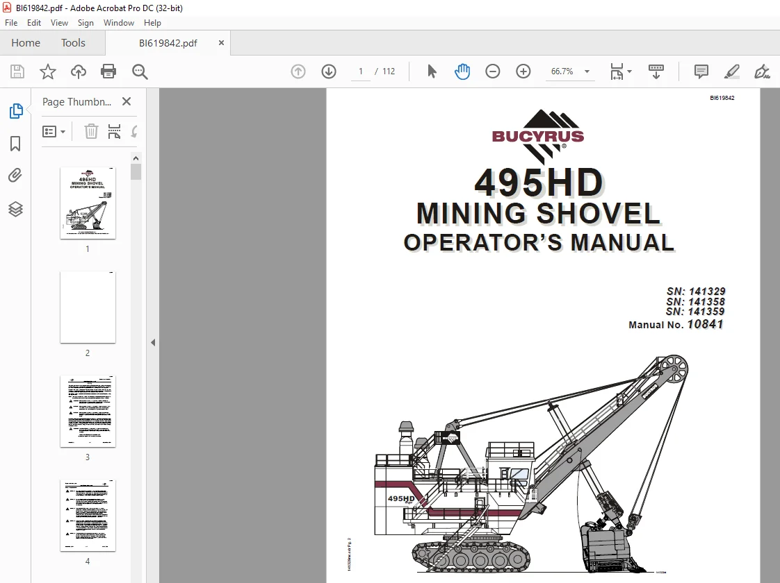
SN:: 141329
SN:: 141358
SN:: 141359
This manual is designed to assist the owner in the operation of this machine. By following easy to understand step-by-step procedures the operators and maintenance personnel can perform all tasks in a safe manner. When a systematic and thorough maintenance/service procedure is used for this machine, a minimum of unplanned downtime and more reliable operation will result.
- Safe operation of the machine minimizes production delays and costly damage to equipment. Carefully study and follow all recommended procedures in this manual. Safety guidelines are intended to prevent accidents from occurring and are provided in the interest of all mine personnel.
- Overall safety depends upon the use of good judgment and the alertness of the entire mining crew. Throughout this section, and the remainder of the manual, the use of the terms “LEFT, RIGHT, FRONT, and REAR” refer to machine locations as viewed by the operator sitting in the operator’s seat in the cab.
- THIS MANUAL IS NOT THE PARTS BOOK, and cannot be used as reference material to order parts. A separate, detailed parts book has been supplied for this purpose.
IMAGES PREVIEW OF THE MANUAL:
TABLE OF CONTENTS:
CAT BUCYRUS 495HD MINING SHOVEL OPERATOR’S MANUAL 10841 – PDF DOWNLOAD
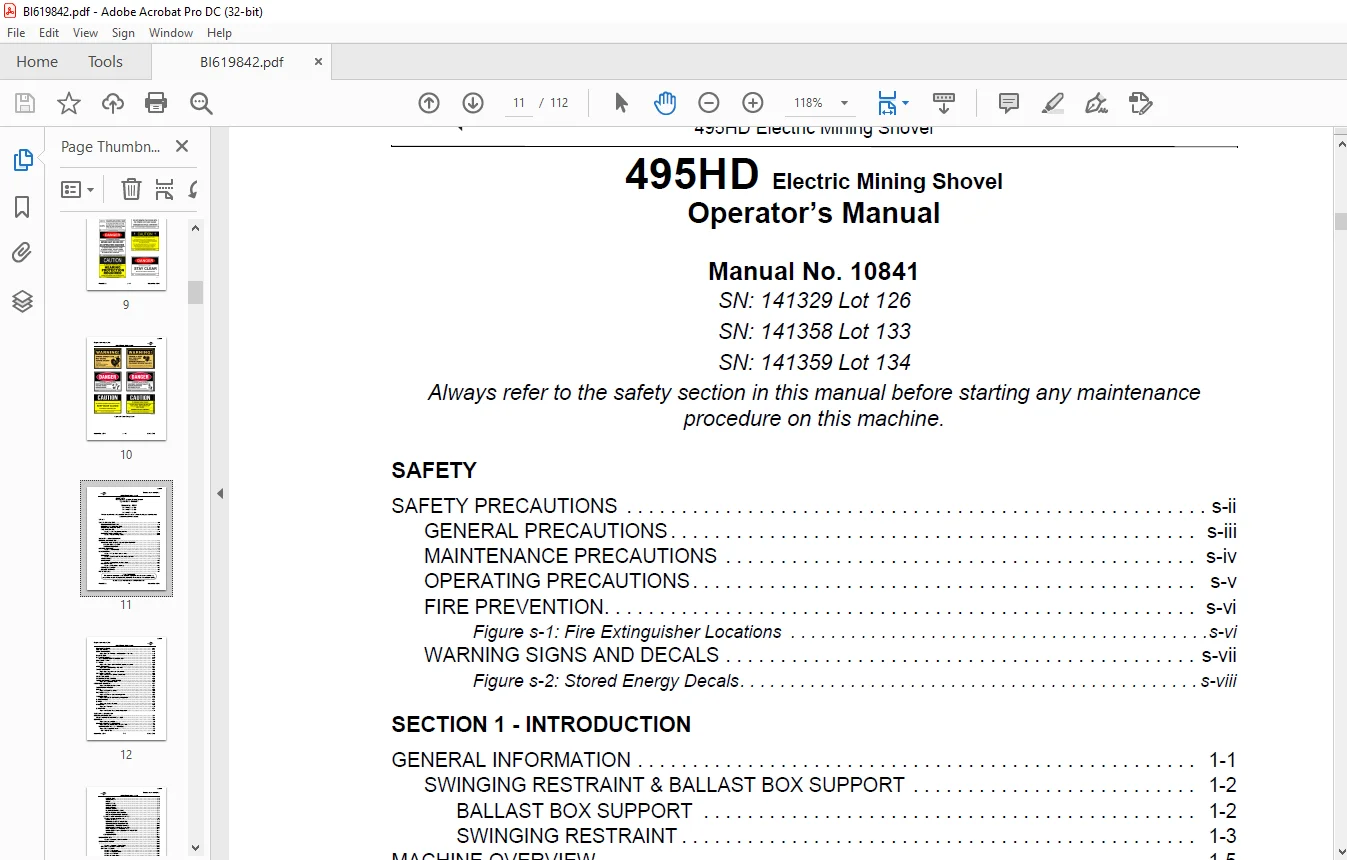
SAFETY
SAFETY PRECAUTIONS s-ii
GENERAL PRECAUTIONS s-iii
MAINTENANCE PRECAUTIONS s-iv
OPERATING PRECAUTIONS s-v
FIRE PREVENTION s-vi
Figure s-1: Fire Extinguisher Locations s-vi
WARNING SIGNS AND DECALS s-vii
Figure s-2: Stored Energy Decals s-viii
SECTION 1 – INTRODUCTION
GENERAL INFORMATION 1-1
SWINGING RESTRAINT & BALLAST BOX SUPPORT 1-2
BALLAST BOX SUPPORT 1-2
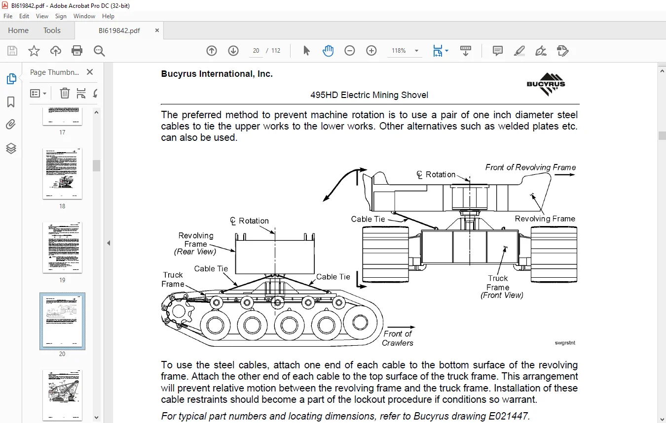
SWINGING RESTRAINT 1-3
MACHINE OVERVIEW 1-5
Figure 1-1: Nomenclature 1-5
LOWER WORKS 1-6
Figure 1-2: Truck Frame and Crawlers 1-6
CRAWLERS 1-7
Figure 1-3: Crawler and Truck Frame Section View 1-8
TRUCK FRAME 1-9
SWING RACK 1-10
Figure 1-4: Swing Rack and Roller Circle 1-10
ROLLER CIRCLE 1-11
Figure 1-5: Roller Circle Assembly 1-11
PROPEL MACHINERY 1-12
COLLECTOR RINGS 1-13
ROTATING DECK 1-14
REVOLVING FRAME 1-14
CENTER PINTLE 1-14
DECK EXTENSIONS 1-16
Figure 1-6: Deck Extensions and Ballast Box – Plan View 1-16
BALLAST BOX 1-16
MACHINERY HOUSE 1-16
VERTICAL BOARDING LADDER, LEFT 1-17
BOARDING STAIRS 1-19
A-FRAME 1-20
Figure 1-7: A-Frame and Front End Support Components 1-20
HOIST MACHINERY 1-21
Figure 1-8: Hoist Machinery – Plan View 1-21
SWING MACHINERY 1-22
Figure 1-9: Swing Machinery Components 1-22
CROWD MACHINERY 1-23
Figure 1-10: Crowd Machinery Components 1-23
OPERATOR’S CAB 1-24
COMPRESSED AIR SYSTEM 1-25
AUTOMATIC LUBRICATION SYSTEM 1-26
Figure 1-11: Lubrication Room 1-26
FRONT END EQUIPMENT 1-27
Figure 1-12: Front End Equipment 1-27
SUSPENSION STRANDS 1-27
BOOM 1-28
Figure 1-13: Boom Assembly 1-28
RUNNING ROPES 1-29
Figure 1-14: Ropes – General Arrangement 1-29
SADDLE BLOCK 1-30
Figure 1-15: Saddle Block Bushing Arrangement 1-30
DIPPER HANDLE 1-31
DIPPER 1-32
Figure 1-16: Dipper Assembly 1-32
PADLOCKS 1-33
Figure 1-17: Padlocks 1-33
DIPPER TRIP 1-34
Figure 1-18: Dipper Trip, General Arrangement 1-34
SECTION 2 – OPERATION
GENERAL INFORMATION 2-1
OPERATION NEAR ELECTRICAL LINES 2-1
CONTROLS 2-3
Figure 2-1: Operator’s Cab 2-3
PRIMARY OPERATING CONTROLS 2-4
Figure 2-2: Operator’s Control Consoles in Cab 2-4
CONTROLS ON THE LEFT CONSOLE 2-5
Figure 2-3: Left Control Console 2-5
LEFT JOYSTICK 2-6
DIPPER TRIP 2-6
SIGNAL HORN 2-6
RADIO 2-6
HOIST BRAKE 2-6
CROWD BRAKE 2-6
SWING BRAKE 2-7
PROPEL BRAKE 2-7
CLIMATE CONTROL PANEL 2-7
WINDSHIELD WIPER SWITCH 2-7
WINDSHIELD WASHER SWITCH 2-7
CONTROLS ON THE RIGHT CONSOLE 2-8
Figure 2-4: Right Control Console 2-8
RIGHT JOYSTICK 2-9
CONTROL STOP PUSHBUTTON 2-9
CONTROL RESET PUSHBUTTON 2-10
DIG/PROPEL TRANSFER SWITCH 2-10
EMERGENCY STOP PUSHBUTTON 2-10
MAIN POWER OFF PUSHBUTTON 2-11
EARTH CONTINUITY LOCKOUT PUSHBUTTON 2-11
TELEPHONE 2-11
HEATED MIRRORS 2-11
2-11
OPERATOR’S SEAT 2-12
Figure 2-5: Operator’s Seat – Front View 2-12
OPERATOR’S DISPLAY 2-13
2-13
Figure 2-6: Operator’s Display Panel 2-14
DISPLAY AREA AND INDICATORS 2-15
DISPLAY SCREENS 2-16
Figure 2-7: Title Screen 2-16
Figure 2-8: Language Screen 2-16
Figure 2-9: Icon Screen 2-17
Figure 2-10: Active Alarm 2-17
Figure 2-11: New Alarm 2-18
Figure 2-12: Alarms Help 2-18
Figure 2-13: Rope Reeving/Pintle Tightening 2-19
Figure 2-14: Rope Reeving/Pintle Tightening Help 2-20
Figure 2-15: Calibration Limits 2-20
Figure 2-16: Limit Calibration Help 2-21
Figure 2-17: Fault Counters/Operating Hours 2-21
Figure 2-18: PLC Menu Screen 2-22
Figure 2-19: Typical Bearing Temperature Screen 2-22
Figure 2-20: Operator’s Screen 2-23
AUXILIARY CONTROLS 2-24
REMOTE START PANEL 2-24
PHASE SEQUENCE LIGHT 2-24
DRIVE CABINETS TEMPERATURE LIGHT 2-24
PLC POWER ON LIGHT 2-24
SYSTEM READY LIGHT 2-25
AUXILIARY GROUND FAULT LIGHT 2-25
INCOMPLETE SEQUENCE LIGHT 2-25
SYSTEM RUN PUSHBUTTON 2-25
AIR COMPRESSOR START/STOP PUSHBUTTONS 2-25
HOUSE LIGHT CIRCUIT BREAKERS 2-25
LIGHTING TRANSFER SWITCH 2-26
LUBRICATION CONTROL PANEL 2-26
WINDSHIELD WIPERS 2-26
WINDSHIELD WASHER 2-27
SECTION 3 – MACHINE SPECIFICATIONS
TYPICAL MACHINE SPECIFICATIONS 3-1
Table 3-1: Weights 3-1
Table 3-2: Front End Equipment 3-1
Table 3-3: Rope Data 3-1
Table 3-4: Typical Dimensions and Working Ranges 3-2
GENERAL ESTIMATED COMPONENT WEIGHTS 3-3
LOWER WORKS 3-3
UPPER WORKS 3-5
FRONT END 3-7
SECTION 4 – MACHINE OPERATION
PRE-START CHECKS 4-1
WALK-AROUND GROUND LEVEL INSPECTION 4-1
ON-BOARD INSPECTION 4-2
START-UP, OPERATION AND SHUTDOWN 4-3
MACHINE START-UP 4-3
RESTARTING AFTER AN ELECTRICAL FAULT 4-5
MACHINE OPERATION 4-5
MACHINERY MOTIONS 4-6
HOIST MOTION 4-6
CROWD MOTION 4-7
PROPEL MOTION 4-8
Figure 4-1: Propel – Straight Forward/Reverse 4-8
SWING MOTION 4-9
PROPER SWING MOTION 4-10
STEERING 4-12
COUNTER-ROTATION TURNS 4-13
POSITIONING THE MACHINE 4-14
BACK-UP METHOD 4-14
DRIVE-BY METHOD 4-15
START OF THE DIG CYCLE 4-16
Figure 4-2: Force the Dipper Lip into the Bank 4-16
Figure 4-3: Variations on Dipper Penetration 4-18
Figure 4-4: Dig with the Dipper Beneath the Boom Point 4-19
ENGAGING THE BANK 4-19
Figure 4-5: Engage the Bank Under the Boom Point 4-19
Figure 4-6: Hoist Force Opposes Crowd Force 4-20
Figure 4-7: Make Effective Use of the Hoist Effort 4-20
SLOPE LIMITATIONS 4-21
Figure 4-8: Slope vs Degrees 4-21
Figure 4-9: Rollover and Operation Limits 4-22
EXCAVATED MATERIAL 4-23
OPERATION CHECKS 4-23
OPERATING HINTS 4-24
STOPPING THE MACHINE 4-25
SHUTDOWN 4-25
Questions? Email us: [email protected]
https://vimeo.com/861563268?share=copy
PLEASE NOTE:
- This is the same manual used by the dealers to diagnose and troubleshoot your vehicle
- You will be directed to the download page as soon as the purchase is completed. The whole payment and downloading process will take anywhere between 2-5 minutes
- Need any other service / repair / parts manual, please feel free to contact [email protected] . We still have 50,000 manuals unlisted
S.M