Description
CAT Bucyrus 495HF MINING SHOVEL Maintenance & Operation Manual BI619632 PDF DOWNLOAD
FILE DETAILS:
CAT Bucyrus 495HF MINING SHOVEL Maintenance & Operation Manual BI619632 PDF DOWNLOAD
Language : English
Pages : 660
Downloadable : Yes
File Type : PDF
IMAGES PREVIEW OF THE MANUAL:


TABLE OF CONTENTS:
CAT Bucyrus 495HF MINING SHOVEL Maintenance & Operation Manual BI619632 PDF DOWNLOAD
SN 141325
SN 141327
Manual No-10851
Safety Precautions 4
General Precautions 5
Maintenance Precautions 6
Operating Precautions 7
Warning Signs And Decals 9
Introduction 27
General Information 27
SWINGING RESTRAINT & BALLAST BOX SUPPORT 28
Ballast Box Support 28
Swinging Restraint 29
Machine Overview 31
Lower Works 32
Crawlers 33
Truck Frame 34
Swing Rack 35
Roller Circle 36
Propel Machinery 37
Collector Rings 38
Rotating Deck 39
Revolving Frame 39
Center Pintle 40
Deck Extensions 42
Ballast Box 42
Machinery House 42
Boarding Stairs 43
Vertical Boarding Ladder 44
A-Frame 45
Hoist Machinery 46
Swing Machinery 47
Crowd Machinery Overview 48
OPERATOR’S CAB 49
Compressed Air System 50
Automatic Lubrication System 51
Lube Reservoir fill / Overflow Plumbing 52
Front End Equipment 53
Suspension Strands 53
Boom 54
Running Ropes 55
Saddle Block 56
Dipper Handle – Hydraulic Crowd 56
Dipper 57
Padlocks 58
Dipper Trip 59
Typical Machine with HydraCrowd Specifications 60
General Estimated Component Weights 62
Lower Works 62
Upper Works 63
Front End 65
Operation 71
General Information 71
Operation Near Electrical Lines 71
Operator’s Seat 73
Adjustable Armrest 73
Adjustable Footrest 74
Controls 75
Primary Operating Controls 75
Controls On The Left Console 76
Left Joystick 77
Dipper Trip 77
Signal Horn 77
Start Pushbutton 77
PLC Power On 78
Drive Cabinet Temperature 78
Incomplete Sequence 78
System Ready 78
Phase Sequence 78
Auxiliary Ground Fault 78
Hoist Brake 78
Crowd CONTROL 78
Swing Brake 78
Propel Brake 78
HVAC Unit Selector 78
Temperature 78
HVAC System Control 78
HVAC Fan Speed 78
Cabin Lights 78
Auxiliary Heater 79
Controls On The Right Console 80
Right Joystick 81
Emergency Stop Pushbutton 82
Windshield Wiper Switches 82
Control Stop Pushbutton 82
Control Reset Pushbutton 82
Air Compressor 83
Dig/propel Transfer Switch 83
Main Power Off Pushbutton 83
Earth Continuity Lockout Pushbutton 83
Seat Position 83
Radio Receiver with CD Changer 84
Heated Mirrors 84
Man On Ground 84
Operator’s Display 84
Display Area and Indicators 85
Display Screens 85
Lubrication Control Panel 92
Fire Suppression System 93
Pre-start Checks 93
Walk-around Ground Level Inspection 94
On-board Inspection 96
Start-up, Operation And Shutdown 97
Machine Start-up 97
Restarting After An Electrical Fault 98
Machine Operation 98
Machinery Motions 99
Hoist Motion 99
Crowd Motion100
Propel Motion101
Swing Motion102
Proper Swing Motion103
Steering104
Counter-rotation Turns106
Positioning the Machine107
Back-up Method107
Drive-by Method108
Start Of The Dig Cycle109
Engaging The Bank112
Slope Limitations114
Excavated Material116
Operation Checks116
Operating Hints117
Stopping the Machine118
Shutdown118
Lubrication121
Lubrication Principles121
Greasing Main AC Drive Motors122
1 Type of Grease122
2 Initial Commissioning122
3 Maintenance122
4 Regreasing Intervals123
Lubricant Selection123
Oil Fill Capacities125
Types Of Lubricants And Capacities Guidelines125
Quantities for First Fill of Lubricants125
Automatic Lubrication System126
Lube Room127
Lube Reservoir fill / Overflow Plumbing128
Auto Lube Control Panel129
Lower Works Lubrication129
Propel Machinery Lubrication130
Lubricant Replacement/sampling131
Lubricant Change Cycle131
Revolving Frame Lubrication132
Hoist Machinery Lubrication133
Hoist Oil Cooler134
Filter Element Cleaning137
Hoist Rope Rollers Lubrication138
Oil Pump139
Hydraulic Crowd Machinery Lubrication139
Pump Drive Transmission (Pdt)140
Swing Machinery Lubrication141
Air Compressor Lubrication142
Front End Lubrication143
Lincoln Type SL-1 Lubricant Injectors144
SL-1 Lubricant Injector Operation146
Injector Advantages148
Air Compressor Lubricant148
Hydraulic Cleanliness149
Contamination Control149
Filters150
Moisture Removal150
MPO – Multipurpose OIL151
RWRL – Running Wire Rope Lubricant152
EGL – Enclosed Gearcase Lubricant153
MPG – Multipurpose Grease156
OGL – Open Gear Lubricant160
Certified Lubricants Listing164
Preventive Maintenance173
Introduction173
Preventive Maintenance Program173
Elements of an Effective Maintenance Program174
Scheduled Preventive Maintenance Program175
General Safety Considerations175
Maintenance During Machine Operation176
Maintenance Precautions177
Preventive Maintenance for Lubrication178
Lubricant Cleanliness179
Frequency of Inspection and Maintenance180
Maintenance Schedules180
Maintenance Inspection Check Points180
Daily181
Every 100 Hours or Weekly184
Every 500 Hours Or Monthly185
Every 1250 Hours or Quarterly187
Every 2500 Hours or Semi-Annually190
5000 Hours or Annually193
10,000 Hours Or Every 2 Years195
20,000 Hours Or Every 4 Years195
Hydraulic Crowd Service Schedule196
Service Procedures223
Lower Works223
Truck Frame Assembly223
Swing Rack Assembly224
Roller Circle Rail Replacement – Lower224
Roller Circle Rail Replacement – Upper225
Roller Circle Assembly227
Roller Circle Adjustment229
Adjustment Procedure229
Run-in Procedure for the Roller Circle229
Roller Circle Segment Removal230
Roller Circle – Roller Replacement231
Crawler Belts232
Crawler Belt Maintenance232
Crawler Belt Tension Adjustment233
Crawler Shoe Replacement235
Crawler Belt Replacement236
Crawler Side Frame Assembly237
Crawler Side Frame Maintenance238
Slide Bar Replacement239
Load and Idler Rollers243
Roller Removal or Replacement243
Propel Assembly246
Installation Notes248
Main Propel Drive Shaft Removal249
Main Propel Shaft – Disassembly252
Tumbler Rebuild Procedure253
Propel Machinery255
Propel Gearcase Removal256
Propel Gearcase Installation257
Propel Planetary Gearcase259
Propel Motors260
Propel Motor Removal260
Propel Motor Installation262
Revolving Frame263
Center Pintle264
Center Pintle Adjustment269
Center Pintle Sleeve Removal269
Collector Rings271
Collector Ring Inspection272
Collector Ring Repair272
Rotating Deck272
Swing Machinery273
Swing Support Mounting Bolts275
Swing Motor275
Swing Blower275
Swing Motor Removal276
Swing Motor Installation277
Swing Planetary Gearcase277
Swing Gearcase Removal278
Gearcase Inspection279
Swing Pinion Shafts280
Swing Pinion Shaft Removal281
Swing Pinion Shaft Disassembly282
Swing Pinion Shaft Assembly283
Swing Pinion Shaft Installation284
Hoist Machinery285
Hoist Motor Removal286
Motor Coupling Shaft289
Hoist Gearcase Assembly290
Hoist Gearcase Repair294
Hoist Drum Assembly297
Hoist Gear Replacement299
Bearing Removal301
Bearing Installation302
Hoist Oil Cooler304
Hoist Mounting Bolts305
Hoist Limit Switch306
Crowd Machinery Overview307
Power Module/Lower Hydraulic Tank308
Main Pump Removal309
Pdt Removal312
Pump Timing & Installation316
Crowd Motor Removal & Installation318
Tuning Set-up Procedure322
Tachometer Removal & Installation325
Boom Tube Removal & Replacement326
Power Module Removal330
Oil Circulation Pump REMOVAL & replacement334
Flushing/PDT Lube Motor Disassembly & Replacement337
Operator’s Cab Mounting340
Operator’s Seat Installation341
Footrest Installation343
Machinery House344
Walkways, Stairways, and Handrails345
Boarding Stairs345
Vertical Boarding Ladder, left348
Boom Assembly351
Boom Repair352
Boom Limit Switch Installation353
Boom Point Sheaves355
Boom Point Sheave Removal and Disassembly356
Boom Point Sheave Reassembly and Installation358
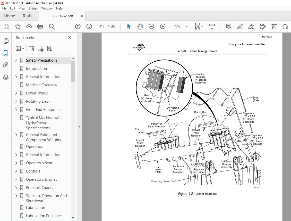
Boom Bumper359
Saddle Block360
saddle Block Hose Guides & Guards360
Saddle Block Repair361
Saddle Block Removal362
Dipper Handle – Hydraulic Crowd362
Dipper Handle Guide Bushing Replacement363
Dipper Handle Removal364
Dipper Handle Installation365
Linear Encoder Removal & Installation366
Hydraulic Crowd Component Weights & Weight Distribution367
Sleeve & Cylinder Removal368
Sleeve & Cylinder Installation374
Hydraulic Crowd Cylinder Removal377
Rod End Relief Valve Replacement382
Sleeve Tube Removal & Replacement383
Static Rod Seal Installation385
Guide Bushing Wear & Rotation387
LatchFreeTM Dipper Assembly391
Dipper Assembly391
Latch Bar Adjusting393
Dipper Door bumpers394
Dipper Removal & Installation395
Dipper Door Snubbers402
Snubber Adjustment403
Dipper Pitch Brace404
Dipper Padlock405
Dipper Trip Assembly408
A-Frame409
Auxiliary Winch411
Hoist Rope Support Roller412
Boom Support Ropes413
Wire Ropes414
Wire Rope Inspection415
Hoist Rope Reeving & Replacement415
Dipper Trip Rope Reeving & Replacement419
Hoist and Crowd Limit Systems420
Setting Limits In The Hoist & Crowd System421
Crowd Slowdown/Stop Limits423
Retract Slowdown/Stop Limits425
Lower Slowdown/Stop Limits427
Hoist Slowdown/Stop Limits428
Brakes and Couplings431
Brakes431
Disc Brake Operation432
Maintenance432
Brake Adjustment Specifications432
Hoist Brake433
Hoist Brake Adjustment435
Hoist Brake Installation437
Hoist Brake Wear & Release Switches437
Propel Brake438
Propel Brake Adjustment440
Propel Brake Installation442
Tachometer Mounting & Alignment444
Swing Brake446
Swing Brake Installation448
Swing Brake Wear & Release Switches449
Swing Brake Burnishing450
Spring Replacement — All Brakes450
Friction Disc Replacement — All Brakes452
O-Ring Replacement — All Brakes453
Brake Wear & Release Switches — Single Disc Brakes455
Brake Wear & Release Switches — Multiple Disc Brakes456
Couplings457
Grid Couplings457
Lubrication457
Coupling Disassembly and Grid Removal458
Grid Coupling Installation459
Seal Replacement without Hub Removal462
Grid Coupling Alignment464
Gear Couplings465
Coupling Installation465
Gear Coupling Alignment467
Hoist Coupling Shaft Alignment468
Circulation Pump Coupling Alignment469
Flushing/pdt Lube Motor – Coupling Alignment470
Hydraulic Crowd Motor To Pdt Coupling Alignment470
Digital Tachometer Coupling473
Compressed Air System477
Air Compressor477
Lockout Valves479
Safety Warnings481
Air Filtration485
House Filter Fans485
Lubrication486
Dynavane Air Cleaner487
Air Conditioner488
Specifications489
Engineering Data495
Capscrew (Bolt) Grade495
Bolt Tightening495
Torque Wrench Method495
Turn-of-nut Method497
Measurement Systems499
Linear Measurements499
Area Measurements499
Volume Measurements500
Torque Measurements501
Weight Measurements – Conventional502
Split Flange Assembly Procedure503
Wire Locking Capscrews505
Torque Nut Installation506
Expansion Bolt Installation506
Tightening Procedure for 125-Inch Torque Nut507
Tightening Procedure for 15-Inch Torque Nut508
Tightening Procedure for 2-Inch Torque Nut509
Tightening Procedure for 2-Inch Torque Nut510
Tightening Procedure for 35-Inch Torque Nut511
Procedure For Use Of Mechanical Tensioner On 35 Inch Crawler Rods512
Initial Tensioning512
Final Tensioning512
Tightening Procedures – Expansion Bolts514
Rack & Roller Torque Rod, Tapered Sleeve & 10 Inch Torque Nut514
Hoist Torque Rod, Tapered Sleeve & 162 Inch Torque Nut515
Swing Torque Rod & Tapered Sleeve & 325 Inch Torque Nut517
Torque Nut Removal Procedure519
Thread Lubrication519
Torque Nut Helpful Hints520
Locking Assemblies520
Installation, Series B115520
Removal, Series B115521
Locking Assembly Removal522
Pinion and Hub Installation523
Removal from a Shaft523
Mounting a Pinion or Hub on a Shaft523
Pre-heat Advance Requirements – Pinions and Hubs526
Motor Coupling Pre-Heat Advance Requirements526
Maintenance Welding528
Welding Electrodes529
Repair Welding of Cracks530
Preheat531
Welding Technique531
Repair Welding of Broken Parts532
Repair Welding Swing Rack Teeth533
Preparation533
Swing Rack Welding Electrodes533
1 All welding is to be done using oven dry E11018-M low hydrogen electrodes Connect an electrode drying oven as close as possible to the work area Set the oven temperature at 300°F (149°C) As sealed containers of electrodes are opened, place th533
Preheat533
Welding Procedure535
Welding and Cutting Equipment537
Stress Relieving & Temperature Measuring Equipment538
Wire Rope Care and Maintenance539
Storage539
Checking Diameter539
Handling Wire Rope540
Seizing Wire Rope541
End Preparations/Terminations543
Wire Rope Clips543
Wire Rope Clip Application543
Wedge Sockets545
Inspection of Sheaves and Drums546
Breaking In a New Wire Rope547
Inspection Data548
Guideline to Inspections and Reports549
Wire Rope Inspection Criteria550
Reduction in Rope Diameter550
Rope Stretch551
Abrasion552
Corrosion552
Kinks552
Bird Caging552
Localized Conditions552
Heat Damage552
Protruding Core552
Damaged End Attachments553
Peening553
Scrubbing553
Fatigue Fracture553
Broken Wires553
Electric Arc554
Seals554
Seal Installation555
Gearcase Sealing556
Hydraulic Crowd Service Procedures561
Hydraulic System Cleanliness561
Hydraulic System Oil Contamination Guide562
Crowd Machinery Overview563
Hydraulic Crowd Cylinder Overview564
Cylinder Control Manifold Overview565
Auxiliary Power Unit Overview568
Power Module/lower Tank Overview569
Lower Tank, Crowd Motor, Transmission & Pumps Overview570
Flushing/pdt Lube Motor Overview571
Circulation Filter Overview572
Manifolds Overview573
Oil Circulation Manifold Overview574
Pump Control Manifold Overview575
Upper Hydraulic Tank Overview576
Oil Circulation Pump Overview578
Isolator Tank Overview579
Oil Cooler & Plumbing Overview580
Hydraulic Crowd Sensor Locations581
Cylinder Sensors581
Power Module Sensors582
Upper Hydraulic Tank Sensors586
Pump Control Manifold Sensor587
Auxiliary Power Unit Sensor588
Inspection589
Pdt Leak Inspection589
Circulation Plumbing Inspection590
Oil Circulation Pump Inspection592
Isolator Troubleshooting592
Isolator Tank Inspection593
Isolator Manifold Inspection594
Vacuum Breaker Inspection595
Isolator Plumbing Inspection596
Service Procedures597
Hydraulic Crowd Start-up Procedure597
Standard System Flushing & Filtration598
Complete System Flushing & Filtration600
Initial System Oil Fill602
System Top Off604
System Oil Drain – Partial606
System Oil Drain – Complete607
Auxiliary Power Unit Fill & Filter Replacement610
Pdt – Initial Oil Fill612
Pdt – Oil Top Off613
Pdt – Oil Level Check614
Pdt – Oil Drain615
Hydraulic Crowd Cooler Cleaning616
Purging The Main Pumps617
Hydraulic System Prefill Filter Replacement618
Upper Tank Return Filter Cleaning & Replacement619
Isolator Removal And Replacement621
Isolator Draining622
Circulation Filter Replacement623
Boom Pressure Hose Removal & Installation624
Pressure Hose Positioning627
Boom Return Hose Removal & Installation628
Return Hose Positioning631
Main Pump Pressure Hose Removal & Installation632
Hydraulic Crowd Service Schedule635
Schematics638
Schematics638
Side View639
Deck Plan640
OGL System A & B Schematic641
Grease System C Schematic642
Air Schematic643
Hydraulic Crowd Troubleshooting Schematics644
10851_5-31zpdf 0
Page 1 0
10851_5-31zpdf 0
Page 1247
Questions? Email us: [email protected]
https://vimeo.com/855680483?share=copy
DESCRIPTION:
CAT Bucyrus 495HF MINING SHOVEL Maintenance & Operation Manual BI619632 PDF DOWNLOAD
GENERAL INFORMATION
This manual is designed to assist the owner in the operation and maintenance of this machine.By following easy to understand step-by-step procedures the operators and maintenance personnel can perform all tasks in a safe manner.
- When a systematic and thorough maintenance/service procedure is used for this machine, a minimum of unplanned downtime and more reliable operation will result. Throughout this section, and the remainder of the manual, the use of the terms “LEFT, RIGHT, FRONT, and REAR” refer to machine locations as viewed by the operator sitting in the operator’s seat in the cab.
- THIS MANUAL IS NOT THE PARTS BOOK, and cannot be used as reference material to order parts. A separate, detailed parts book has been supplied for this purpose. Periodic additions or revisions may be made to this manual
- It is the policy of Bucyrus International, Inc. to improve its products whenever possible and practical to do so. The company reserves the right to make changes or add improvements to its machines at any time.
- This will be without incurred obligations to install such changes on machines sold previously. Due to this ongoing program of product research and development some procedures, specifications and parts may be altered in a constant effort to improve our machines.
PLEASE NOTE:
- This is the same manual used by the dealers to diagnose and troubleshoot your vehicle
- You will be directed to the download page as soon as the purchase is completed. The whole payment and downloading process will take anywhere between 2-5 minutes
- Need any other service / repair / parts manual, please feel free to contact [email protected] . We still have 50,000 manuals unlisted
G.P