
CAT Bucyrus 49HX 49HR (24 VDC Control Systems) Electrical Operation & Troubleshooting Manual BI619460 – PDF DOWNLOAD
$28.95
CAT Bucyrus 49HX 49HR (24 VDC Control Systems) Electrical Operation & Troubleshooting Manual BI619460 – PDF DOWNLOAD
Description
CAT Bucyrus 49HX 49HR (24 VDC Control Systems) Electrical Operation & Troubleshooting Manual BI619460 – PDF DOWNLOAD
FILE DETAILS:
CAT Bucyrus 49HX 49HR (24 VDC Control Systems) Electrical Operation & Troubleshooting Manual BI619460 – PDF DOWNLOAD
Language : English
Pages : 129
Downloadable : Yes
File Type : PDF
DESCRIPTION:
CAT Bucyrus 49HX 49HR (24 VDC Control Systems) Electrical Operation & Troubleshooting Manual BI619460 – PDF DOWNLOAD
OVERVIEW:
- The 49HR is an electric drill designed by Bucyrus International Inc. ® This instruction discusses its
electrical control system. A separate instruction covers the operation of the operator display. Please
refer to the hydraulic and mechanical documentation for help with other features of the drill.
This manual is written to help the user understand the workings and general operation of the 49HR
electrical control system. Certain objects referred to in this manual and in the schematics as “options”
are only present on drills where that particular feature has been purchased. On other systems, those
items are either not wired or not functioning. - It is important to read this manual with respect to the actual schematics supplied with your drill. Certain
design enhancements may have been made to your machine, which improve the operation of various
systems. Therefore, there may be some differences between the operation described in this manual and
the actual operation of the drill.
GENERAL MACHINE DESCRIPTION:
Drill Overview:
- The 49HR rotary blast hole drill incorporates DC motor drives, proportional hydraulics, a programmable
logic controller (PLC), and other technically advanced devices in a form that promotes high performance
and production, low operating costs, and operator comfort. All operator functions are electronically
controlled and the ergonomically designed operator interface provides improved efficiency. - The rotary and hoist/pulldown motions are powered by specially built blower cooled excavator grade DC
mill motors. Each of the motors is controlled by its own independent static (electronic) DC drive that
provides complete control over motor speed, direction and torque (motoring and regenerating). The
drives incorporate advanced digital controls which aid troubleshooting and minimize downtime. Motor
speed control is achieved by variable armature voltage control with fixed (but range selectable) shunt
field current levels. Both the rotary and hoist/pulldown motors are physically mounted on the head
assembly and move up and down with the drill stems during the drilling operation. The rotary motion
incorporates multiple gear reductions which are housed in a head mounted gearbox. The hoist/pulldown
motion also incorporates multiple gear reductions in a head mounted gearbox, but its final drive
mechanism is a rack and pinion. The rack teeth are located on the vertical structure of the mast
assembly. No chains are used as part of the drive mechanism. - The propel motion consists of dual independent crawler mechanisms that are hydraulically powered.
Each hydraulic drive motor is connected to its respective drive tumbler by means of a heavy-duty
gearbox. No chains are used in the propel drive train. Control of the hydraulic drive system is provided
by electronically controlled proportional valves, as described in this manual. - The hydraulic pumps are powered by direct coupling to one of the output shafts of a dual shafted squirrel
cage induction motor. The other output shaft of this motor is coupled to a screw compressor which is
used during the drilling operation to clear chips and dust from the hole being drilled. The screw
compressor incorporates a special unload system that reduces the horsepower demanded from the
compressor during idle and propel operation. This, in turn, allows more power to be available to the
propel pumps when propelling and minimizes power consumption during other non-drilling periods of
time on the drill.
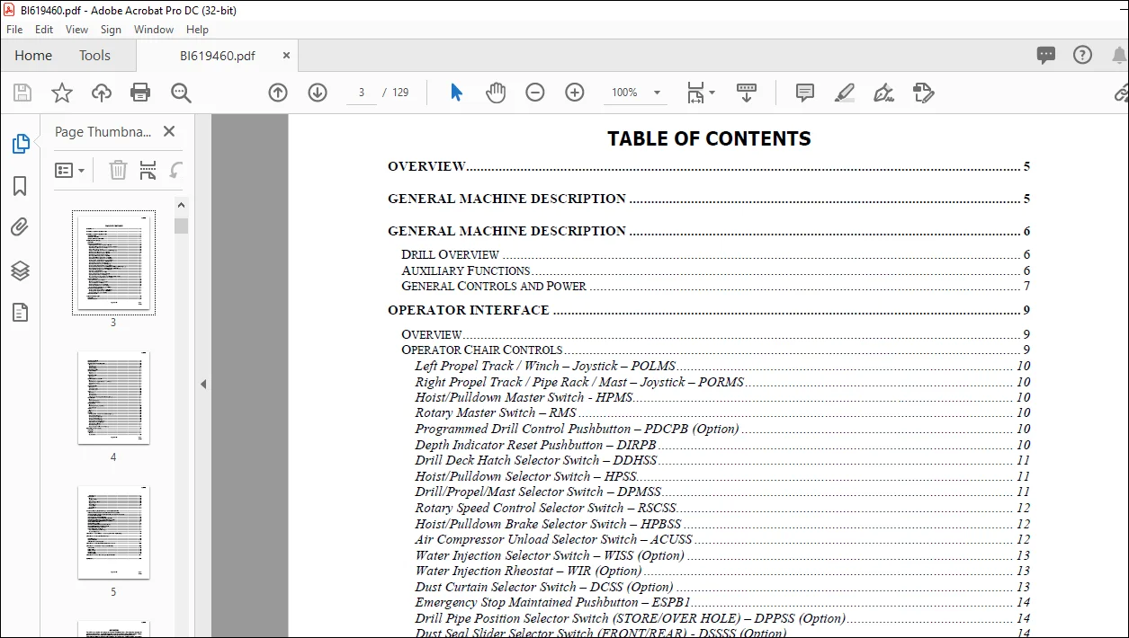
TABLE OF CONTENTS:
CAT Bucyrus 49HX 49HR (24 VDC Control Systems) Electrical Operation & Troubleshooting Manual BI619460 – PDF DOWNLOAD
OVERVIEW 5
GENERALMACHINE DESCRIPTION 5
GENERALMACHINE DESCRIPTION 6
DRILL OVERVIEW 6
AUXILIARY FUNCTIONS 6
GENERAL CONTROLS AND POWER 7
OPERATOR INTERFACE 9
OVERVIEW 9
OPERATOR CHAIR CONTROLS 9
Left Propel Track / Winch – Joystick – POLMS 10
Right Propel Track / Pipe Rack / Mast – Joystick – PORMS 10
Hoist/Pulldown Master Switch – HPMS 10
Rotary Master Switch – RMS 10
Programmed Drill Control Pushbutton – PDCPB (Option) 10
Depth Indicator Reset Pushbutton – DIRPB 10
Drill Deck Hatch Selector Switch – DDHSS 11
Hoist/Pulldown Selector Switch – HPSS 11
Drill/Propel/Mast Selector Switch – DPMSS 11
Rotary Speed Control Selector Switch – RSCSS 12
Hoist/Pulldown Brake Selector Switch – HPBSS 12
Air Compressor Unload Selector Switch – ACUSS 12
Water Injection Selector Switch – WISS (Option) 13
Water Injection Rheostat – WIR (Option) 13
Dust Curtain Selector Switch – DCSS (Option) 13
Emergency Stop Maintained Pushbutton – ESPB1 14
Drill Pipe Position Selector Switch (STORE/OVER HOLE) – DPPSS (Option) 14
Dust Seal Slider Selector Switch (FRONT/REAR) – DSSSS (Option) 14
Propel Speed Range Selector Switch – POSRSS 14
Horn Pushbutton – SHNPB1 14
Tool Wrench Selector Switch – TWSS 14
Breakout Wrench Selector Switch – BOWSS 15
Pipe Rack Selector Switch – PRSS (Option) 15
Manual Leveling Jack Control Switches – JRRSS, JFLRSS, JRLSS 15
Automatic Leveling Jack Control Switch – JACSS 15
CONSOLE CONTROLS 16
Ground Test Pushbutton – GTPB 16
Exterior Lights Selector Switch – ELSS 16
Thermostat Control – HVACTC 16
HVAC Fan Selector Switch – HVACFSS 16
HVAC Mode Selector Switch – HVACMSS 16
Boarding Stairs Cab Selector Switch – BSCSS 17
MACHINERY HOUSE CONTROLS 17
Air Compressor Start Pushbutton – ACSTARTPB 17
Air Compressor Stop Pushbutton – ACSTOPPB 17
Emergency Stop Pushbutton – ESPB2 17
OPERATOR DISPLAY 17
MACHINE OPERATION 19
OVERVIEW 19
MACHINE STARTUP 19
BI619460
Page 3 of 128 Issued:
X-4138
MACHINE SHUTDOWN 19
CONTROL ENABLE 19
MACHINE SETUP AND CALIBRATION 20
Overview 20
Head Calibration 20
Setting Limits 21
Machine Settings 22
OPERATIONAL MODE 23
AIR COMPRESSOR 23
Drill Air 23
Venting 23
BOARDING STAIRS 23
Operation 23
Alarms 24
HOIST/PULLDOWN &ROTARY 24
Overview 24
Hoist/Pulldown – Speed, Direction, and Force 24
Hoist/Pulldown Brake 24
Rotary 25
JACKS & LEVELING 25
Operation 25
Automatic Leveling 26
Retract Switches 26
MAST 26
Operation 26
Mast Lock Pins 26
Mast Brace Pins 27
A-Frame Lock Pins (Angle Hole Drilling Option) 27
OIL COOLERS 27
Overview 27
Hydraulic Oil Cooler 27
Compressor Oil Cooler 27
PIPE HANDLING 27
Overview 27
Extending/Retracting Pipe Rack 28
Pipe Rack Gate 28
PROPEL 28
Overview 28
WINCH 28
OPTIONS 29
Air Compressor Variable Volume Control (Option) 29
Bit Lubricator (Option) 29
Cold Temperature (Option) 29
Fire Suppression (Option) 30
Multiple Pipe Rack (Option) 30
Pipe Thread Lubricator (Option) 30
Radio Remote Propel (Option) 31
Water Injection (Option) 34
Dust Curtain (Option) 34
Hydraulic Upper Window Hatch (Option) 34
CONTROL SYSTEM (PLC) 35
OVERVIEW 35
NETWORK 35
Overview 35
Connections 36
BI619460
Page 4 of 128 Issued:
X-4138
Node Settings 37
HARDWARE 38
Overview 38
Standard “Nodes” 38
Processor 39
Communication Cards 40
Digital Inputs 40
Digital Outputs 40
Analog Inputs 41
Analog Outputs 42
PLC RESET 43
STARTUP, TESTS, ADJUSMENTS, & TROUBLESHOOTING 44
PRELIMINARY CHECKS BEFORE APPLYING POWER TO THE MACHINE 44
PHASE SEQUENCE, AUXILIARY MOTOR ROTATION, AND LIGHT PLANT CHECKS 44
DC POWER SUPPLY CHECKS 45
CONTROL SYSTEM TROUBLESHOOTING 46
DIGITAL HYDRAULIC VALVES ELECTRICAL CHECKS 46
PROPORTIONAL HYDRAULIC VALVES ELECTRICAL SETUP 50
AIR COMPRESSOR AND HYDRAULIC PUMP START-UP 58
AUTOMATIC LUBRICATION 61
DRILL LEVELING SYSTEM 62
ROTARY & HOIST/PULLDOWN DRIVE START-UP 64
HEAD ENCODER CHECKS AND REPLACEMENT 74
WATER INJECTION SYSTEM START-UP 74
CABLE REEL SYSTEM START-UP 74
Proportional Hydraulic Card Setup 74
Cable Reel Operation 76
APPENDIX A – CAB DISPLAY ALARMS (ANF/ANWMESSAGES) 79
APPENDIX B – PLC LED DIAGNOSTICS 98
PROCESSOR LED’S 98
REMOTE I/O LED’S 100
ANALOG INPUT / OUTPUT CARDS 101
APPENDIX C – PLC DIAGNOSTIC BUFFER EVENTS 102
APPENDIX D – PROFIBUS NODE DIAGNOSTICS 122
NODE STATE 122
ERROR TYPE 122
MODULE STATE 122
CHANNEL TYPE 122
CHANNEL ERROR 122
APPENDIX E – CAB RACK ANALOG DIAGNOSTICS 127
REVISIONS 128
IMAGES PREVIEW OF THE MANUAL:
Need help? Contact: [email protected]
PLEASE NOTE:
- This is not a physical manual but a digital manual – meaning no physical copy will be couriered to you. The manual can be yours in the next 2 mins as once you make the payment, you will be directed to the download page IMMEDIATELY.
- This is the same manual used by the dealers inorder to diagnose your vehicle of its faults.
- Require some other service manual or have any queries: please WRITE to us at [email protected]
S.V