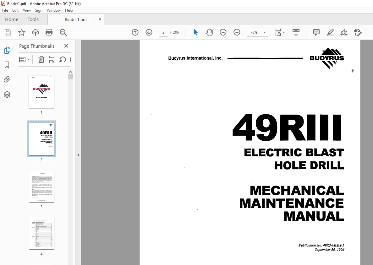
CAT BUCYRUS 49RIII ELECTRIC BLAST HOLE DRILL MECHANICAL MAINTENANCE MANUAL BI005281 – PDF DOWNLOAD
$28.95
CAT BUCYRUS 49RIII ELECTRIC BLAST HOLE DRILL MECHANICAL MAINTENANCE MANUAL BI005281 – PDF DOWNLOAD
Description
CAT BUCYRUS 49RIII ELECTRIC BLAST HOLE DRILL MECHANICAL MAINTENANCE MANUAL BI005281 – PDF DOWNLOAD
FILE DETAILS:
CAT BUCYRUS 49RIII ELECTRIC BLAST HOLE DRILL MECHANICAL MAINTENANCE MANUAL BI005281 – PDF DOWNLOAD
Language : English
Pages : 206
Downloadable : Yes
File Type : PDF
DESCRIPTION:
CAT BUCYRUS 49RIII ELECTRIC BLAST HOLE DRILL MECHANICAL MAINTENANCE MANUAL BI005281 – PDF DOWNLOAD
FOREWORD
- The purpose of this manual is to provide information concerning the general maintenance of the 49-RIII Rotary Blast Hole Drill. The Model 49-RIII consists of three major units, the lower works, the mainframe and the mast. The lower works provides a foundation for the mainframe and contains the necessary equipment to propel the drill.
- The mainframe includes the hydraulic system, main air system, and the machinery house. The machinery house encloses the majority of the mechanical equipment necessary for the main air system, the hydraulic systems and electrical control systems.
- The machinery house is pressurized with filtered air to minimize dirt and heat build-up. The operator’s cab, mounted to the mainframe, includes the operator’s station, and encloses the majority of the controls necessary to operate the drill. The mast contains the drill pipe and drilling tools, the pipe racks, and the rotary and pulldown machinery.
- This manual consists of six chapters, each divided into sections. A table of contents is located in the front of the manual.
CHAPTER 1
MECHANICAL MAINTENANCE
SECTION 1 – MAINTENANCE PROCEDURE
GENERAL
This section of the manual described those aspects of preventive maintenance such as scheduled reports and safety precautions as they pertain to the 49-RIII drill.
MAINTENANCE SCHEDULES AND REPORTS
- Ideally, all maintenance should be approached from the preventive standpoint and on a regularly scheduled basis. Obviously, this approach keeps downtime to a minimum and results in reduced maintenance costs. To establish a preventive upkeep program, scheduled inspections and an operator’s daily report are the most useful tools available.
- Scheduled inspections should be conducted by the Mine Mechanical and Electrical Maintenance Departments since they are the most qualified. Either department should generate a certain amount of paperwork such as inspection records that become a part of the mine’s permanent file on the machine. The inspection records should be explicit, complete, and cover every part of the machine.
- Each machine operator should complete a daily record of the machine’s performance. This record should include time worked, time down, reasons for all delays, and observations on any unusual conditions encountered during operation. From these records, items that can potentially cause machine downtime can be corrected or prevented immediately, or scheduled for a future date when the machine availability can be coordinated with the other mine activities.
Each problem should be thoroughly reviewed and evaluated before scheduling any maintenance or repair. The following points should be considered during the evaluation
1. Is the problem one of normal wear?
2. Is the problem caused by machine application?
3. Is the problem a result of operator error?
4. Is the problem a result of unavoidable circumstances?
5. Is the problem of a repetitive nature?
6. By leaving the repairs to a later date, will
any other component be affected?
7. Can repairs be accomplished immediately?
8. Will the cost of repairs immediately rather
than later be worthwhile?
9. How long will the machine be down?
Once maintenance or repair has been scheduled, take the following points into consideration to minimize downtime and expense.
1. Are all tools and equipment needed to accomplish
maintenance or repair available
on the job, and are they in good repair?
2. Are all replacement parts on hand and
readily available?
3. Is replacement of auxiliary parts, such as
seals and bearings, necessary to accomplish
repair, and have they been ordered?
4. Is all disassembly and reassembly data
available?
5. Have repair crews been scheduled?
6. Will there be adequate supervision on hand
for the repair crews?
7. Has the manufacturer been consulted for
Service or Engineering assistance?
8. How long will the machine be down?
IMAGES PREVIEW OF THE MANUAL:
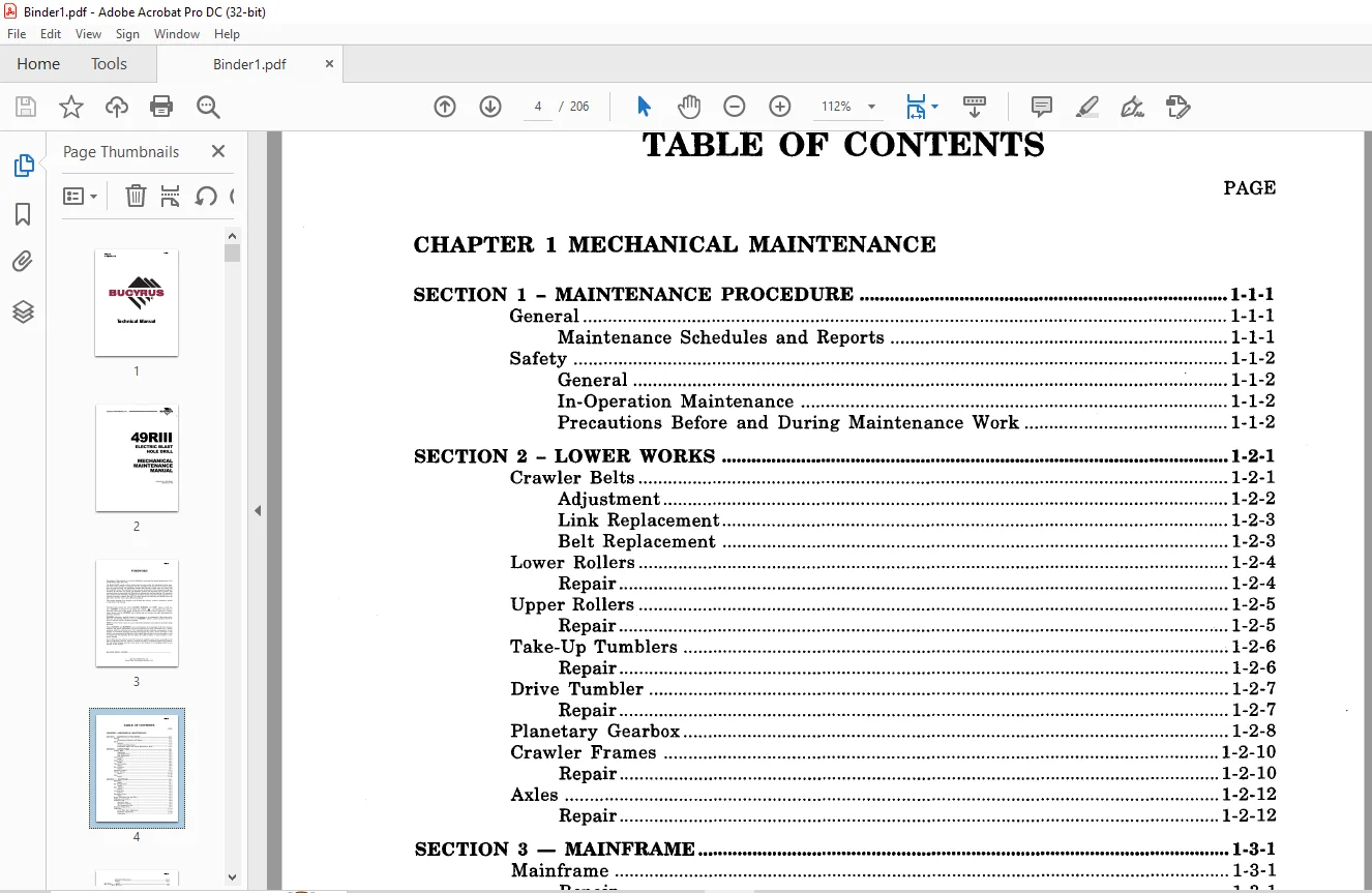
TABLE OF CONTENTS:
CAT BUCYRUS 49RIII ELECTRIC BLAST HOLE DRILL MECHANICAL MAINTENANCE MANUAL BI005281 – PDF DOWNLOAD
CHAPTER 1 MECHANICAL MAINTENANCE
SECTION 1 – MAINTENANCE PROCEDURE 1·1·1
General 1-1-1
Maintenance Schedules and Reports 1-1-1
Safety 1-1-2
General 1-1-2
In-Operation Maintenance 1-1-2
Precautions Before and During Maintenance Work 1-1-2
SECTION 2 – LOWER WORKS 1·2·1
Crawler Belts 1-2-1
Adjustment 1-2-2
Link Replacement 1-2-3
Belt Replacement 1-2-3
Lower Rollers 1-2-4
Repair 1-2-4
Upper Rollers 1-2-5
Repair 1-2-5
Take-Up Tumblers 1-2-6
Repair 1-2-6
Drive Tumbler 1-2-7
Repair 1-2-7
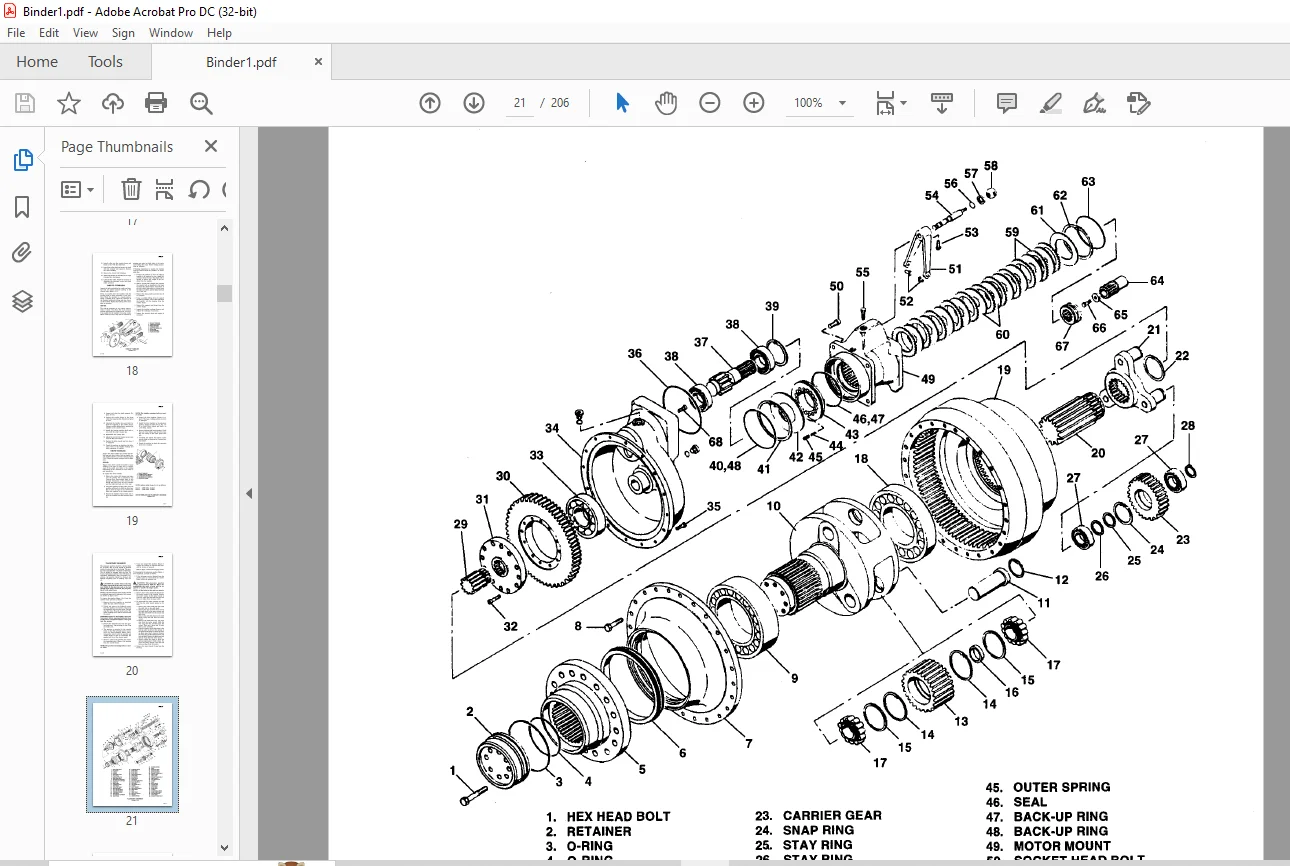
Planetary Gearbox 1-2-8
Crawler Frames 1-2-10
Repair 1-2-10
Axles 1-2-12
Repair 1-2-12
SECTION 3 – MAINFRAME 1·3·1
Mainframe 1-3-1
Repair 1-3-1
Bit Viewing Hatch 1-3-1
Repair 1-3-2
Mast A-Frame 1-3-2
Repair 1-3-2
Leveling Jacks 1-3-2
Repair 1-3-4
Machinery House 1-3-6
Repair 1-3-6
House Ventilation Fan and Filter 1-3-6
Walkways and Ladders 1-3-8
Operator’s Cab 1-3-9
Operator’s Seat 1-3-9
Operator’s Controls 1-3-9
Air Conditioning Unit 1-3-9
Hydraulic Pump Drive 1-3-9
Cable Reel 1-3-11
Level Wind Drive Adjustment 1-3-11
Hydraulic Adjustments 1-3-14
Lubrication 1-3-17
BI005281
Hydraulic Maintenance 1-3-17
Repair 1-3-17
SECTION 4 – MAST 1-4-1
Mast Structure 1-4-1
Repair 1-4-1
Mast Safety Slings 1-4-2
Repair 1-4-2
Rotary Gearcase 1-4-2
Drive Shaft Adjustment 1-4-3
Repair 1-4-3
Rotary Motor 1-4-9
Rotary Coupling (Optional) 1-4-9
Repair 1-4-9
Rotary Shock Coupling 1-4-10
Repair 1-4-10
rotary Shock coupling 1-4-11
Repair 1-4-11
Rotary/Pulldown Guide Frame 1-4-12
Guide Roller Adjustment 1-4-12
Repair 1-4-14
Pulldown Gearcase 1-4-17
Repair 1-4-17
Hoist Brake 1-4-22
Inspection 1-4-22
Brake Wear Adjustment 1-4-23
Replacement of Friction Discs 1-4-23
Disassembly of Magnet Body and Armature 1-4-24
Reassembly of Magnet Body and Armature 1-4-24
Pipe Racks 1-4-25
Repair 1-4-25
Tool Wrenches 1-4-28
Repair 1-4-28
Casing Tong Jib Crane 1-4-29
Pipe Positioner 1-4-30
Auxiliary Winch 1-4-30
Mast Braces 1-4-32
Repair 1-4-32
Adjustment 1-4-32
CHAPTER 2 HYDRAULIC SYSTEM
SECTION 1 – SYSTEM OPERATION 2-1-1
Cylinder Circuit 2-1-1
Propel Circuit 2-1-1
SECTION 2 – GENERAL MAINTENANCE 2-2-1
Hydraulic System Cleanliness 2-2-1
Oil Requirements 2-2-1
Oil and Filter Changes , 2-2-1
Weekly Maintenance Checks 2-2-1
Oil Reservoir Repairs 2-2-2
BI005281
Leveling Jack Counterbalance Valve Pressure Relieving Procedure 2-2-2
Rear Jacks 2-2-2
Front Jack 2-2-2
Prestart Inspection 2-2-3
Hydraulic Systems Tests 2-2-3
Propel Pump Charge Pressure Check 2-2-4
Control Pressure Check 2-2-4
Propel Enable Valve and Low Speed Select Check 2-2-4
Jack Cylinder Check in Manual Mode 2-2-5
Flow Control Check 2-2-5
Jack Cylinder Drift Test 2-2-6
Brake Release Pressure Check 2-2-6
Propel Brake Emergency Release Check 2-2-6
Propel Pump Main Relief Pressure Check 2-2-7
Crawler Function Check 2-2-7
Bit Viewing Hatch Check 2-2-7
Boarding Stair Check 2-2-7
Main Flow Valve Check 2-2-7
Breakout Wrench and Tool Wrench Check 2-2-8
Dust Curtain Cylinders 2-2-8
Dust Seal Slider 2-2-8
Mast Lock 2-2-8
Mast Brace Lock Cylinders 2-2-8
A-Frame Lock Cylinders 2-2-8
Mast Lock Constant Pressure Check 2-2-8
Mast Brace Constant Pressure Check 2-2-8
A-Frame Lock Constant Pressure Check 2-2-9
Mast Raise/Lower 2-2-9
Auxiliary Winch 2-2-9
Hydraulic Central Lube Drive Pressure Check 2-2-10
Window Guard Function Check 2-2-10
Water Injection Drain Valves Check 2-2-10
Water Injection Pump Function Check 2-2-11
Water Injection Washdown Check 2-2-12
Check Jacks in Auto Level Mode 2-2-12
Pipe Rack Position Check 2-2-13
Pipe Rack Lock and Gate Cylinder Port Relief Setting 2-2-13
Pipe Thread Lubricator Check 2-2-13
Pipe Positioner Function Check 2-2-13
Center Guide Function Check plus Constant Pressure Check 2-2-13
Automatic breakout wrench check 2-2-14
CHAPTER 3 AIR SYSTEM
SECTION 1- SYSTEM OPERATION 3-1·1
Main Air System 3-1-1
SECTION 2 – GENERAL MAINTENANCE 3-2-1
Main Air System 3-2-1
General 3-2-1
Intake Air Filter 3-2-1
Filter Replacement 3-2-1
Compressor Radiator 3-2-2
BI005281
SECTION 3 – ROTARY SCREW COMPRESSOR
(A·C COMPRESSOR CORP. KS·31.AC(X) OR KS·27·AC) 3·3·1
Description 3-3-1
Coupling Alignment 3-3-2
Parallel Misalignment 3-3-2
Angular Misalignment 3-3-3
Start-Up Procedure 3-3-3
Shutdown 3-3-5
Controls and Instruments 3-3-5
Air Pressure Control System 3-3-5
Variable Volume Feature (Optional) 3-3-9
Lubrication System 3-3-9
Compressor Oil System 3-3-9
Lubrication – compressor 3-3-10
Lubricant Specifications 3-3-10
Filling Oil System (Initially) 3-3-10
Oil Level Gauge 3-3-10
Adding Oil Between Changes 3-3-10
Draining Oil System 3-3-12
Refilling Oil System 3-3-13
Compressor Oil Strainer and Filters 3-3-13
Compressor Oil Cooler 3-3-13
Temperature Control Valve 3-3-14
Compressor Oil Separator Elements 3-3-15
Air Filters 3-3-16
Maintenance Schedule 3-3-18
Preventative maintenance 3-3-19
Intake Valve Service 3-3-19
Air End Input Shaft Oil Seal Replacement 3-3-21
CHAPTER 4 DUST CONTROL
SECTION 1 – GENERAL MAINTENANCE 4-1·1
Drilling Platforms and Dust Curtains 4-1-1
Filter/Clone® System (Tipton) 4-1-1
Daily Maintenance Checks 4-1-1
Monthly Maintenance Checks 4-1-1
Six Month Maintenance Checks 4-1-2
Water Injection System 4-1-2
Operation 4-1-2
Filling Water Tank 4-1-3
Deck Washdown System (Optional) 4-1-3
Operating Principle 4-2-1
SECTION 2 – MAINTENANCE OF FILTERICLONE® (TIPTON) 4-2·1
Maintenance 4-2-1
CHAPTER 5 LUBRICATION
SECTION 1 • LUBRICATION PROCEDURES 5·1·1
General 5-1-1
Lubricant Cleanliness 5-1-1
Lubrication Points 5-1-1
Lubrication Benchmarks 5-1-8
BI005281
SECTION 2 – LINCOLN AUTOMATIC SYSTEM 5-2-1
Troubleshooting Systems 5-2-1
Air Locks 5-2-1
Dirty Supply Lines 5-2-1
All Injectors Do Not Work Properly 5-2-1
After Venting, The Indicator Stems on the Injectors do not Return to
Their Normal Position 5-2-1
Graco Pump Servicing 5-2-2
Pressure Relief Procedure 5-2-2
Replacing the Throat Seals 5-2-2
Disconnecting the Reciprocator and Displacement Pump 5-2-2
Lubrication 5-2-10
APPENDIX Al . GEAR INSPECTION lA-l
General lA-1
APPENDIX A2 . BOLT TORQUING 2A-l
Torque Wrench Method 2A-1
Turn Of The Nut Method 2A-2
APPENDIX A3 – PINION, BRAKE DRUM AND COUPLING INSTALLATION …….••••• 3A-l
Removal From Shaft 3A-1
Mounting On Shaft 3A-l
APPENDIX A4 . LUBE BENCHMARKS 4A-l
MPG – Multi-Purpose Type Grease 4A-1
Scope 4A-1
Application 4A-1
General Requirements 4A-1
Compounding 4A-1
Specific Requirements 4A-1
Notations 4A-1
Air Compressor (Screw Type) Lubricant 4A-2
DPTL – Drill Pipe Thread Lubricant 4A-2
Scope 4A-2
Application 4A-2
General Requirements 4A-2
Specific Requirements 4A-2
MPO – Milti-Purpose Oil 4A-3
Scope 4A-3
Application 4A-3
General Requirements 4A-3
Viscosity Recommendations 4A-3
OGL – Open Gear Lubricant 4A-3
Scope 4A-3
Application 4A-3
Methods of Application 4A-3
General Requirements 4A-3
Type of Lubricants 4A-4
Compounding 4A-4
Specific Requirements for all Types of Lubricants 4A-4
RGL – Regular Type Gear Lubricant 4A-5
Scope 4A-5
Application 4A-5
General Requirements 4A-5
Compounding 4A-5
Viscosity and Viscosity Index 4A-5
BI005281
Notations 4A-6
Rotary Blast Hole Drills 4A-6
Notations , 4A-7
RWRL – Running Wire Rope Lubricant 4A-8
Scope 4A-8
Application 4A-8
General Requirements 4A-8
Compounding 4A-8
Special Requirements 4A-8
HYDO – Hydraulic Oil 4A-9
PAO Synthetic Hydraulic Fluid 4A-9
Parafinnic base Petroleum Hydraulic Fluid .4A-IO
APPENDIX A5 – RECOMMENDED PROCEDURES FOR MAINTENANCE WELDING OF
PRINCIPAL STRUCTURES ON BLAST HOLE DRILLS SA-}
APPENDIX A6 – PREVENTIVE MAINTENANCE CHECK LIST 6A-}
APPENDIX A7· SPECIAL FITS 7A-l
APPENDIX AS – AEROQUIP ORS CONNECTIONS SA-}
Contact us: [email protected]
https://vimeo.com/865221519?share=copy
PLEASE NOTE:
- This is the SAME exact manual used by your dealers to fix your vehicle.
- The same can be yours in the next 2-3 mins as you will be directed to the download page immediately after paying for the manual.
- Any queries / doubts regarding your purchase, please feel free to contact [email protected]
S.M