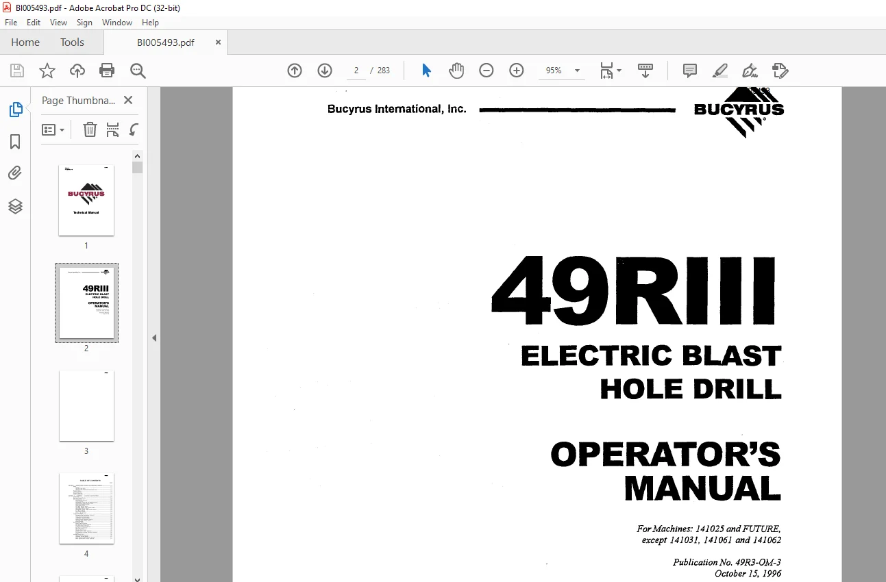
Cat Bucyrus 49RIII Electric Blast Hole Drill Operator’s Manual BI005493 – PDF DOWNLOAD
$28.95
Cat Bucyrus 49RIII Electric Blast Hole Drill Operator’s Manual BI005493 – PDF DOWNLOAD
Description
Cat Bucyrus 49RIII Electric Blast Hole Drill Operator’s Manual BI005493 – PDF DOWNLOAD
FILE DETAILS:
Cat Bucyrus 49RIII Electric Blast Hole Drill Operator’s Manual BI005493 – PDF DOWNLOAD
Language : English
Pages : 283
Downloadable : Yes
File Type : PDF
IMAGES PREVIEW OF THE MANUAL:
DESCRIPTION:
Cat Bucyrus 49RIII Electric Blast Hole Drill Operator’s Manual BI005493 – PDF DOWNLOAD
FOREWORD:
This manual establishes guidelines and furnishes general instructions for the operation of the
Bucyrus 49RIII Rotary Blast Hole Drill.
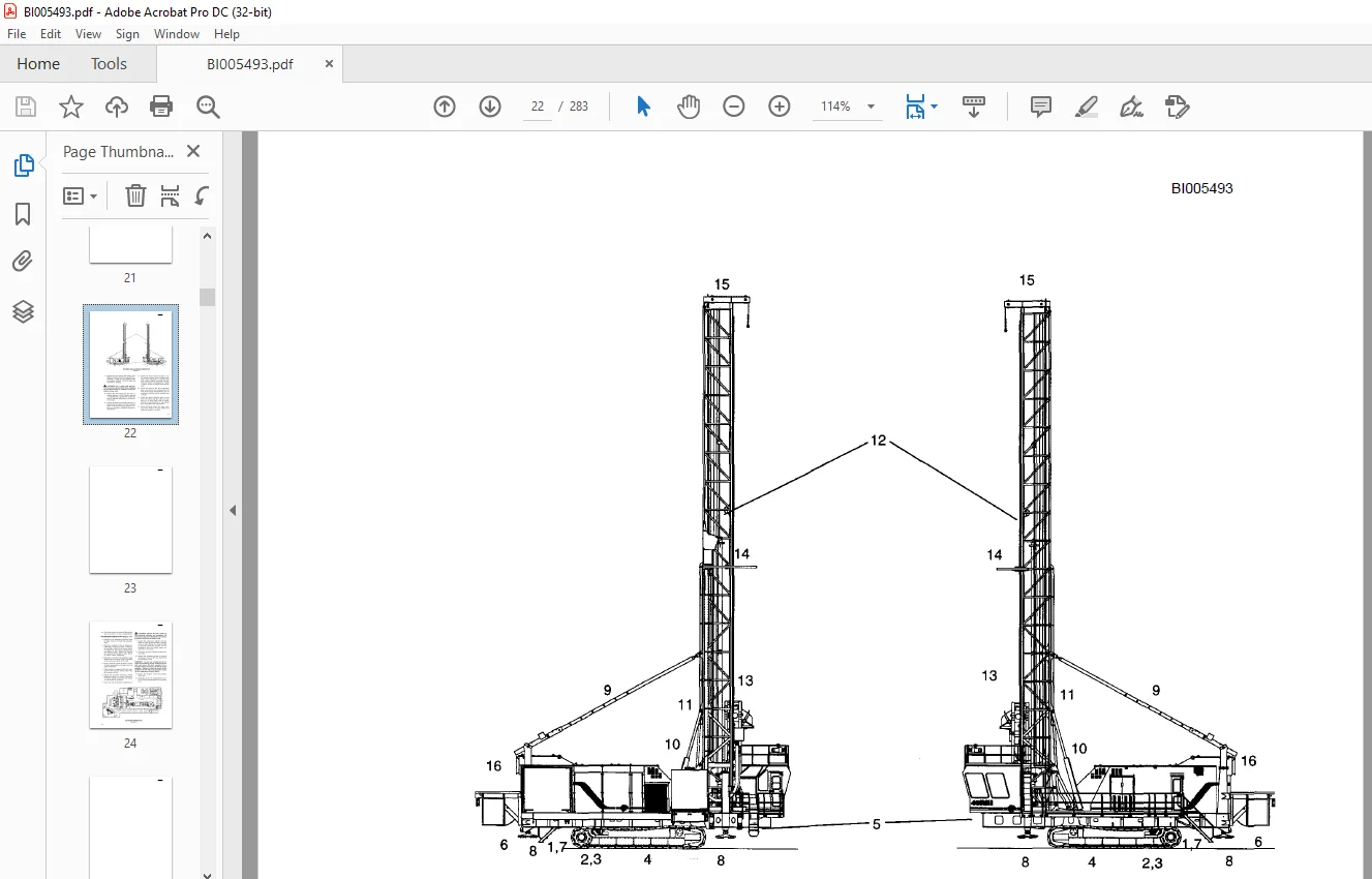
The drill consists of three major units; the lower works, the main frame, and the mast.
- The lower works provides a foundation for the main frame and contains most of the necessary
components to propel the drill. - The main frame is mounted upon the lower works and contains the bailing air compressor
and all controls to operate the drill. The machinery house encloses most of the main frame.
The operator’s cab is located at the rear of the main frame and contains the operator’s station.
The mast is mounted to the rear of the main frame and contains the machinery required for
handling of the tool string, including the hoist/pulldown machinery and the rotary machinery.
This manual is divided into seven sections:
SECTION 2 – Controls-Function and Location
SECTION 3 – Start Up
SECTION 4 – General Operation
SECTION 5 – Drilling
APPENDICES
- Safe operation of a rotary blast hole drill pro motes personal safety and minimizes
delays and costly damage to equipment. - Carefully study and follow all recommended procedures in this manual. Safety guidelines are intended to help prevent accidents from occurring and are pro vided in the interest of all mine personnel.
- Over all safety depends upon a good sense of judge ment and alertness on the part of the entire mining crew.
action as necessary to correct the conditions immediately.
• Wear hard hat, safety shoes and safety glasses at all times.
• When operating or performing maintenance functions, wear snug fitting clothing. Loose clothing can be caught on controls or in moving parts. Remove all jewelry.
• Keep the operator’s cab, ladders, walkways and steps free of materials which cause slip pery conditions or obstacles which create tripping hazards.
• Use proper interior and exterior lighting.
• Do not allow unauthorized personnel on board the machine while in operation.
• Do not begin operation until all personnel are clear of the machine or in a safe position on the machine.
• Use audible signals to warn of machine movements. A signal horn button is pro vided for this purpose.
• Do not propel until the
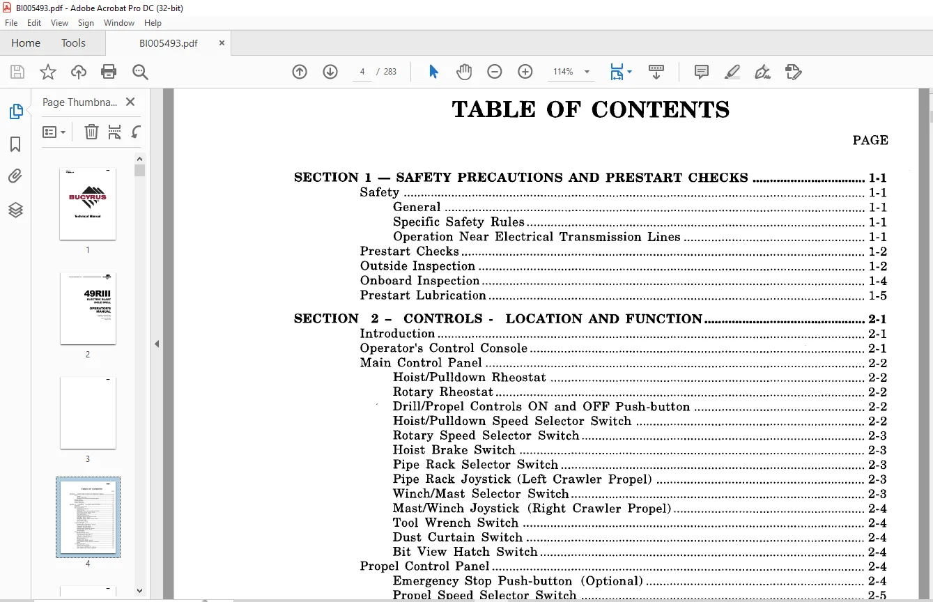
TABLE OF CONTENTS:
Cat Bucyrus 49RIII Electric Blast Hole Drill Operator’s Manual BI005493 – PDF DOWNLOAD
SECTION 1 – SAFETY PRECAUTIONS AND PRESTART CHECKS I-I
Safety 1-1
General 1-1
Specific Safety Rules 1-1
Operation Near Electrical Transmission Lines 1-1
Prestart Checks 1-2
Outside Inspection 1-2
Onboard Inspection 1-4
Prestart Lubrication 1-5
SECTION 2 – CONTROLS – LOCATION AND FUNCTION 2-1
Introduction 2-1
Operator’s Control Console 2-1
Main Control Panel 2-2
HoistlPulldown Rheostat 2-2
Rotary Rheostat 2-2
Drill/Propel Controls ON and OFF Push-button 2-2
HoistlPulldown Speed Selector Switch 2-2
Rotary Speed Selector Switch 2-3
Hoist Brake Switch 2-3
Pipe Rack Selector Switch 2-3
Pipe Rack Joystick (Left Crawler Propel) 2-3
Winch/Mast Selector Switch 2-3
MastlWinch Joystick (Right Crawler Propel) 2-4
Tool Wrench Switch 2-4
Dust Curtain Switch 2-4
Bit View Hatch Switch 2-4
Propel Control Panel , 2-4
Emergency Stop Push-button (Optional) 2-4
Propel Speed Selector Switch 2-5
Compressor Stop Push-button 2-5
Compressor Vent/Drill Switch 2-5
HeaterNent/Air Conditioner Controls 2-5
Operating Mode Selector Switch 2-5
Propel Joysticks 2-5
Selector Switch Panel 2-5
Breakout Wrench Switch 2-5
Pipe Positioner Switch (Optional) 2-6
Dust Seal Switch (Optional) 2-6
A-Frame Lock Switch (Optional) 2-6
Mast Brace Lock Switch 2-6
Mast Lock Switch 2-6
Boarding Stairs Switch 2-6
Pedestal Heater Switch (Optional) 2-6
Fire Suppression System Indicators (Optional) 2-6
RADIO 2-6
Leveling Control Panel 2-6
Manual Leveling Joysticks 2-6
Automatic Leveling Switch 2-7
Water Injection On/Off Switch (Optional) 2-7
Water Injection Flow Control (Optional) 2-7
BI005493
BI005493
SECTION 4 – OPERATION – GENERAL 4-1
Introduction 4-1
Propelling 4-1
Definitions 4-1
Procedure 4-1
Towing 4-4
Cable Reel Operation 4-6
Leveling 4-6
Mast Raising and Lowering 4-8
Mast Raising 4-8
Mast Lowering 4-10
Puldown Machinery Operation 4-12
Auxiliary Winch Operation 4-13
Pipe Rack Operation 4-13
Tool Handling 4-15
General Operating Procedure 4-15
Pipe Loading and Unloading 4-16
Drill Tool String Assembly 4-17
Breakout Wrench Operation 4-22
Drill Tool String Disassembly 4-23
Adding Additional Drill Pipe 4-25
Removal of Multiple Section Drill Pipe 4-27
Angle Drilling 4-28
Dust Suppression System Operation 4-28
SECTION 5 – DRILLING 5-1
Vertical Drilling 5-1
General Operating Procedures 5-1
Beginning The Hole (Collaring) 5-2
Normal Drilling 5-2
Ending the Hole (Reaming) 5-3
APPENDIX 3 – LUBE CHARTS 3A·1
APPENDIX 5 – STABILITY & PROPEL 5A·1
Typical Propel 5A-1
Special Propel Conditions 5A-1
Ending the Hole (Multiple Pipe Sections) 5-4
Drilling Difficult Formations 5-4
Unconsolidated Materials 5-5
Wet or Sticky Formations 5-7
Angle Drilling 5-7
General Operating Procedures 5-7
Programmed Drill Control Drilling 5-8
Preparing to Move 5-9
SECTION 6 – MACHINE SHUTDOWN 6·1
General Considerations 6-1
Shut Down Procedure 6-1
Short Term Storage 6-1
Long Term Storage 6-2
Attended Long Term Storage 6-2
Unattended Long Term Storage 6-2
APPENDIX 1 – TOOL RECOVERY ‘ 1A·1
APPENDIX 2 – PIPE SIZE LIMITATIONS 2A·1
APPENDIX 4 – OPERATOR’S CONSOLE AND LOW VOLTAGE CABINET 4A·1
Need help? Contact: [email protected]
PLEASE NOTE:
- This is the SAME exact manual used by your dealers to fix your vehicle.
- The same can be yours in the next 2-3 mins as you will be directed to the download page immediately after paying for the manual.
- Any queries / doubts regarding your purchase, please feel free to contact [email protected]
S.V