Cat Bucyrus 49RIII Electric Blast Hole Drill Operator’s Manual BI005496 – PDF DOWNLOAD
$26.95
Cat Bucyrus 49RIII Electric Blast Hole Drill Operator’s Manual BI005496 – PDF DOWNLOAD
Description
Cat Bucyrus 49RIII Electric Blast Hole Drill Operator’s Manual BI005496 – PDF DOWNLOAD
FILE DETAILS:
Cat Bucyrus 49RIII Electric Blast Hole Drill Operator’s Manual BI005496 – PDF DOWNLOAD
Language : English
Pages : 120
Downloadable : Yes
File Type : PDF
IMAGES PREVIEW OF THE MANUAL:
DESCRIPTION:
Cat Bucyrus 49RIII Electric Blast Hole Drill Operator’s Manual BI005496 – PDF DOWNLOAD
FOREWORD:
This manual establishes guidelines and furnishes general instructions for the operation of the
Bucyrus 49RIII Rotary Blast Hole Drill.
The drill consists of three major units; the lower works, the main frame, and the mast.
- The lower works provides a foundation for the main frame and contains most of the necessary
components to propel the drill. - The main frame is mounted upon the lower works and contains the bailing air compressor
and all controls to operate the drill. The machinery house encloses most of the main frame.
The operator’s cab is located at the rear of the main frame and contains the operator’s station.
The mast is mounted to the rear of the main frame and contains the machinery required for
handling of the tool string, including the hoist/pulldown machinery and the rotary machinery.
This manual is divided into seven sections:
SECTION 1- Safety Precautions and Prestart Checks SECTION 2 – Controls-Function and Location
SECTION 3 – Start Up
SECTION 4 – General Operation
SECTION 5 – Drilling
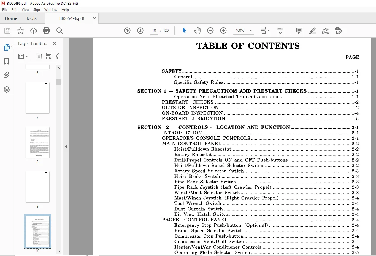
TABLE OF CONTENTS:
Cat Bucyrus 49RIII Electric Blast Hole Drill Operator’s Manual BI005496 – PDF DOWNLOAD
SAFETy 1-1
General 1-1
Specific Safety Rules 1-1
SECTION 1 – SAFETY PRECAUTIONS AND PRESTART CHECKS 1-1
Operation Near Electrical Transmission Lines 1-1
PRESTART CHECKS 1-2
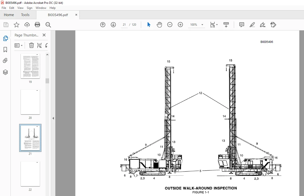
OUTSIDE INSPECTION 1-2
ON-BOARD INSPECTION 1-4
PRESTART LUBRICATION 1-5
SECTION 2 – CONTROLS – LOCATION AND FUNCTION 2-1
INTRODUCTION 2-1
OPERATOR’S CONSOLE CONTROLS 2-1
MAIN CONTROL PANEL 2-2
Hoist/Pulldown Rheostat 2-2
Rotary Rheostat 2-2
Drill/Propel Controls ON and OFF Push-buttons 2-2
Hoist/Pulldown Speed Selector Switch 2-2
Rotary Speed Selector Switch 2-3
Hoist Brake Switch 2-3
Pipe Rack Selector Switch 2-3
BI005496
BI005496
SECTION 4 – OPERATION – GENERAL 4-1
INTRODUCTION 4-1
PROPELLING 4-1
Definitions 4-1
Procedure , 4-1
Towing 4-4
CABLE REEL OPERATION 4-6
LEVELING 4-6
MAST RAISING AND LOWERING 4-8
Mast Raising 4-8
Mast Lowering 4-9
PULLDOWN MACHINERY OPERATION 4-11
AUXILIARY WINCH OPERATION 4-12
PIPE RACK OPERATION 4-12
TOOL HANDLING 4-13
General Operating Procedure 4-13
Pipe Loading and Unloading 4-13
Drill Tool String Assembly 4-14
Breakout Wrench Operation 4-18
Drill Tool String Disassembly 4-20
Adding Additional Drill Pipe 4-21
Removal of Multiple Section Drill Pipe 4-23
Dust Suppression System Operation 4-24
SECTION 5 – DRILLING 5-1
VERTICAL DRILLING 5-1
General Operating Procedures 5-1
Beginning The Hole (Collaring) 5-2
Normal Drilling 5-2
Ending the Hole (Reaming) 5-3
Ending the Hole (Multiple Pipe Sections) 5-4
DRILLING DIFFICULT FORMATIONS 5-4
Unconsolidated Materials 5-5
Horn Push-button 2-7
Depth Indicator Reset Push-button 2-7
Programmed Drill Control Switch 2-8
Emergency Stop Push-button (optional) 2-8
OPERATOR’S DISPLAY TERMINAL 2-8
MACHINERY HOUSE CONTROLS 2-8
Lighting Load Center 2-8
Controls Located On Low Voltage Start Cabinet 2-9
Controls Located On Low Voltage Cabinet 2-9
Controls Located On Programmable Controller Cabinet 2-9
Hoist/Pulldown and Rotary Drive Control Cabinets 2-10
Controls Located On or Near Screw Type Air Compressor 2-10
MISCELLANEOUS CONTROLS 2-10
Lube Control Panel 2-10
SECTION 3 – START-UP 3-1
INTRODUCTION 3-1
MACHINE START-UP 3-1
MACHINERY CHECK 3-2
BREAK-IN OF NEW COMPONENTS 3-2
Rotary Drive Unit Break-In 3-2
Hoist/Pulldown Gearcase Break-In 3-2
Electric Motor Break-In 3-2
BI005496
BI005496
Wet or Sticky Formations 5-7
PROGRAMMED DRILL CONTROL DRILLING 5-7
Preparing to Move 5-8
SECTION 6 – MACHINE SHUTDOWN 6·1
GENERAL CONSIDERATIONS 6-1
SHUT DOWN PROCEDURE 6-1
SHORT TERM STORAGE 6-1
LONG TERM STORAGE 6-2
Attended Long Term Storage 6-2
Unattended Long Term Storage 6-2
APPENDIX 1 – TOOL RECOVERY 1A-1
APPENDIX 2 – PIPE SIZE LIMITATIONS 2A-1
APPENDIX 3 – LUBE CHARTS 3A·1
APPENDIX 4 – STABILITY & PROPEL 4A·1
TYPICAL PROPEL 4A-1
SPECIAL PROPEL CONDITIONS 4A-1
Need help? Contact: [email protected] THE MANUAL:
PLEASE NOTE:
- This is the SAME MANUAL used by the dealerships to diagnose your vehicle
- No waiting for couriers / posts as this is a PDF manual and you can download it within 2 minutes time once you make the payment.
- Your payment is all safe and the delivery of the manual is INSTANT – You will be taken to the DOWNLOAD PAGE.
- So have no hesitations whatsoever and write to us about any queries you may have : heydownloadss @gmail.com
S.V