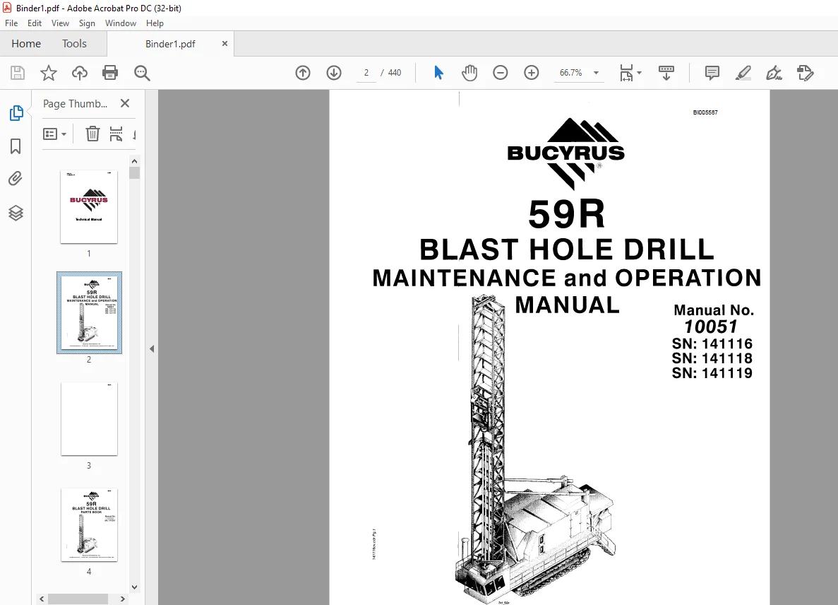
CAT BUCYRUS 59R BLAST HOLE DRILL MAINTENANCE and OPERATION MANUAL 10051 – PDF DOWNLOAD
$28.95
CAT BUCYRUS 59R BLAST HOLE DRILL MAINTENANCE and OPERATION MANUAL 10051 – PDF DOWNLOAD
SN: 141116
SN: 141118
SN:141119
Description
CAT BUCYRUS 59R BLAST HOLE DRILL MAINTENANCE and OPERATION MANUAL 10051 – PDF DOWNLOAD
FILE DETAILS:
CAT BUCYRUS 59R BLAST HOLE DRILL MAINTENANCE and OPERATION MANUAL 10051 – PDF DOWNLOAD
Language : English
Pages : 440
Downloadable : Yes
File Type : PDF
DESCRIPTION:
CAT BUCYRUS 59R BLAST HOLE DRILL MAINTENANCE and OPERATION MANUAL 10051 – PDF DOWNLOAD
SN: 141116
SN: 141118
SN:141119
Operation
SAFETY
- The importance of overall safety in the maintenance of mining equipment should always be emphasized. Many critical components are subject to wear and other deterioration that limits their useful life and makes them expendable. When new, all such parts have a built-in reserve strength against these factors and reasonable loss of durability from gradual wear.
- If, however, inspection and adjustment are neglected, these parts eventually reach a condition where they become a safety problem. Similarly, failure to replace various mechanisms to insure proper performance of the machine also constitutes a safety problem. Study this manual carefully and follow all recommended procedures to avoid unsafe conditions. Review the manual periodically to refresh your knowledge of these procedures. Supervisors, operators and maintenance personnel should continuously follow safe practices.
- The safety alert symbols displayed here, and throughout this manual, are used to call your attention to instructions concerning your personal safety. Carefully read and follow these instructions and observe all SAFETY, DANGER, and CAUTION graphics mounted on various areas of the machine. Be certain anyone servicing this machine is aware of these SAFETY SYMBOLS and their definitions.
- In the event you question your ability to safely perform any of the enclosed maintenance and operational procedures, contact your regional Bucyrus service representative or the factory. The following defines distinctions between safety instructions. In all these definitions the safety alert signal is used.
SAFETY PRECAUTIONS
- Safe operation of a rotary blast hole drill promotes personal safety and minimizes delays and costly damage to equipment. Carefully study and follow all recommended procedures in this manual. Safety guidelines are intended to help prevent accidents from occurring and are provided in the interest of all mine personnel.
- Overall safety depends upon a good sense of judgment and alertness on the part of the entire mining crew. The following is a list of some important safety rules relating to prestart and operation of the 59R drill. The safety instructions given in this manual cover normal daily operations of the machine.
- Additional precautions may be necessary to cover unusual circumstances. Be constantly alert for any potentially dangerous conditions and take action as necessary to correct the conditions immediately.
General Precautions:
• The employment of qualified maintenance personnel, through a scheduled maintenance
program, is the best way to minimize machine downtime and maximize productivity of
equipment.
• Keep hands, feet, and clothing away from rotating parts.
• Wear a hard hat, safety shoes and protective lenses at all times.
• Replace any and all safety and warning placards if they are defaced or removed from the
machine.
• Think before you act. Carelessness is one luxury the service man cannot afford.
• Excessive or repeated skin contact with sealants or solvents may cause skin irritation. In
case of skin contact refer to the Material Safety Data Sheet (MSDS) for that material and the
suggested method of cleanup.
• Inspect safety catches (keepers) on all hoist hooks. Do not take a chance, the load could slip
off of the hook if they are not functioning properly.
IMAGES PREVIEW OF THE MANUAL:
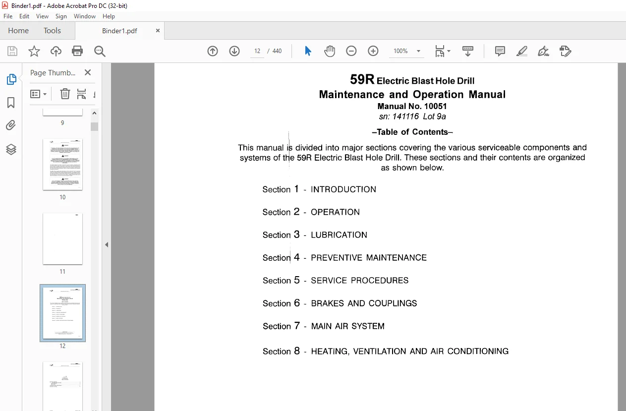
TABLE OF CONTENTS:
CAT BUCYRUS 59R BLAST HOLE DRILL MAINTENANCE and OPERATION MANUAL 10051 – PDF DOWNLOAD
Section 1 – INTRODUCTION
Section 2 – OPERATION
Section 3 – LUBRICATION
Sectio~ 4 – PREVENTIVE MAINTENANCE
Section 5 – SERVICE PROCEDURES
Section 6 – BRAKES AND COUPLINGS
Section 7 – MAIN AIR SYSTEM
Section 8 – HEATING, VENTILATION AND AIR CONDITIONING
SAFETY 5
SAFETY PRECAUTIONS 6
FIRE PREVENTION CONSIDERATIONS 9
OPERATION NEAR ELECTRICALTRANSMISSION LINES 10
PRESTART CHECKS 11
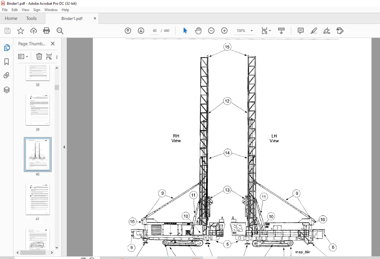
EXTERNAL INSPECTION 11
Daily Inspection Items 12
ONBOARD INSPECTION 14
Onboard Inspection Items 14
PRESTART LUBRICATION 16
MAINTENANCE DURING OPERATION 17
PRECAUTIONS BEFOREAND DURING MAINTENANCE WORK 18
CONTROLS – LOCATION AND FUNCTION 19
OPERATOR’S CONTROL CONSOLE 20
Operator’s Control Console – Overall View 20
MAIN CONTROL PANEL 21
Main Control Panel 21
HOIST/PULLDOWN RHEOSTAT 22
ROTARY RHEOSTAT 22
DRILL/PROPEL CONTROLS ON AND OFF PUSH-BUTTON 22
HOIST/PULLDOWN SPEED SELECTOR SWITCH 23
ROTARY SPEED SELECTOR SWITCH 23
HOIST BRAKE SWiTCH 24
PIPE RACK SELECTOR SWITCH 24
PIPE RACK JOYSTICK (LEFT CRAWLER PROPEL) 24
WINCH/MAST SELECTOR SWITCH 25
MASTIWINCH JOYSTICK (RIGHT CRAWLER PROPEL) 25
TOOL WRENCH SWiTCH 26
DUST CURTAIN SWiTCH 26
BIT VIEW HATCH SWITCH 26
PROPEL CONTROL PANEL 27
Propel Control Panel 27
EMERGENCY STOP PUSH-BUTTON 27
PROPEL SPEED SELECTOR SWiTCH 27
COMPRESSOR STOP PUSH-BUTTON 28
COMPRESSOR VENT/DRILL SWITCH 28
IHEATERNENT/AIR CONDITIONER CONTROLS 28
Feb. 2000 2 – 1 Manual No. 10051
BI005587
BUCYRUS INTERNATIONAL Inc.
59R ELECTRIC BLAST HOLE DRILL
.. ~~
BUC,,Y,,R,U.S
OPERATING MODE SELECTOR SWiTCH 28
PROPEL JOySTiCKS 28
SELECTOR SWITCH PANEL 29
Selector Switch Panel 29
BREAKOUT WRENCH SWiTCH 30
PIPE POSITIONER SWITCH 30
DUST SEAL SWiTCH 30
A-FRAME LOCK SWiTCH 30
MAST BRACE LOCK SWiTCH 30
MAST LOCK SWiTCH 31
BOARDING STAIRS SWITCH 31
PEDESTAL HEATER SWITCH 31
FIRE SUPPRESSION SYSTEM INDiCATORS 31
RADIO 31
LEVELING CONTROL PANEL 32
Leveling Control Panel 32
MANUAL LEVELING JOYSTICKS 33
AUTOMATIC LEVELING SWITCH 33
WATER INJECTION ON/OFF SWITCH 33
WATER INJECTION FLOW CONTROL 33
HORN PUSH-BUTTON 34
DEPTH INDICATOR RESET PUSH-BUTTON 34
PROGRAMMED DRILL CONTROL SWITCH 34
EMERGENCY STOP PUSH-BUTTON 34
OPERATOR’S DISPLAY TERMINAL 35
Operator’s Display Panel 35
MACHINERY HOUSE CONTROLS 36
LIGHTING LOAD CENTER 36
CONTROLS ON THE LOW VOLTAGE START CABINET 36
CONTROLS ON THE LOW VOLTAGE CABINET 37
Low Voltage Cabinet (Typical) 37
CONTROL ON THE PROGRAMMABLE CONTROLLER CABINET 37
Programmable Control Cabinet 37
HOIST/PULLDOWN AND ROTARY DRIVE CONTROL CABINETS 38
Hoist Pulldown and Rotary Drive Cabinets 38
CONTIROLS ON OR NEAR THE AIR COMPRESSOR 39
Air Compressor Mounted Controls 39
MISCELLANEOUS CONTROLS 40
Portable Remote Propel Station (Optional) 40
Hydraulic ReservoirRemote Fill Control Panel 40
Lube Control Panel 41
MACHINE START-UP 42
MACHINERY CHECK 43
BREAK-IN OF NEW COMPONENTS 43
ROTARY DRIVE UNIT BREAK-IN 43
HOIST/PULLDOWN GEARCASE BREAK-IN 43
ELECTRIC MOTOR BREAK-IN 43
MACHINE OPERATION 44
PROPELLING 44
Manual No. 10051 2-2 Feb. 2000
BUCYRUS INTERNATIONAL Inc.
PROPEL PROCEDURE 45
Operator Ctontrols – Propel 46
Propel- Forward orReverse 47
Propel- Gradual Right Hand Turn 47
Propel- Gradual Leeft Hand Turn 48
Propel- Counter-Rotation Left Hand Turn 48
Gradual Turns – 150 Increments 49
TOWING PROCEDURE 50
CABLE REEL OPERATION 51
LEVELING 52
Machine Orientation 52
Controls for Levelling the Machine 54
MAST RAISINGAND LOWERING 54
MAST RAiSING 54
Controls for Raising or Lowering the Mast 55
MAST LOWERING 56
Controls for Angle Drilling 57
PULDOWN MACHINERY OPERATION 58
Controls for Hoist / Pulldown 58
AUXILljt\RYWINCH OPERATION 59
Controls forOperating the Winch 59
PIPE RACK OPERATION 60
Controls for Operating the PipeRracks 61
TOOL HANDLING 64
PIPE LOADINGAND UNLOADING 64
DRILL TOOLSTRINGASSEMBLY 66
Stabilizer Installation 67
Controls for Drill Pipe Installation 67
INSTALLING DRILL PIPE 68
Stabilizer In$tallation 70
Bit InstallatiQn 71
BREA~OUT WRENCH OPERATION 72
DRILL TOOL STRING DISASSEMBLY 73
ADDING ADDITIONAL DRILL PIPE 75
REMOVAL OF MULTIPLE SECTION DRILL PIPE 76
ANGLE DRILLING 77
Jib Crane 78
DUST SUPPRESSION SYSTEM OPERATION 78
VERTICAL DRILLING 79
Controls for Normal Drilling 80
STARTING THE HOLE (COLLARING) 80
NORMAL DRILLING 81
ENDING THE HOLE 83
ENDING THE HOLE (MULTIPLE PIPE SECTIONS) 84
DRILLING DIFFICULT FORMATIONS 84
UNCONSOLIDATED MATERIALS 85
WET OR STICKY FORMATIONS 87
ANGLE DRILLING 88
PROGRAMMED DRILL CONTROL DRILLING 89
Controls for Programmed Drill Control 89
PREPARING TO MOVE 90
Feb. 2000 2-3 Manual No. 10051
BI005587
BUCYRUS INTERNATIONAL Inc.
MACHINE SHUTDOWN 92
SHUTDOWN PROCEDURE 92
SHORT TERM STORAGE 93
LONG TERM STORAGE 94
ATTENDED LONG TERM STORAGE 95
UNATTENDED LONG TERM STORAGE 95
TOOL RECOVERy 96
PIPE SIZE LIMITATIONS 98
Manual
Questions? Email us: [email protected]
https://vimeo.com/865861616?share=copy
PLEASE NOTE:
- This is the same manual used by the dealers to diagnose and troubleshoot your vehicle
- You will be directed to the download page as soon as the purchase is completed. The whole payment and downloading process will take anywhere between 2-5 minutes
- Need any other service / repair / parts manual, please feel free to contact [email protected] . We still have 50,000 manuals unlisted
S.M