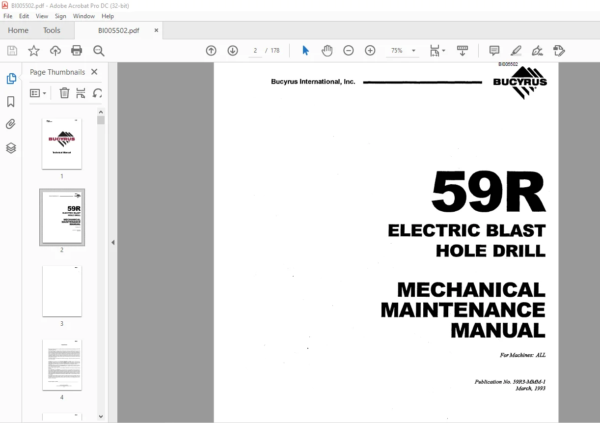
Cat BUCYRUS 59R ELECTRIC BLAST HOLE DRILL MECHANICAL MAINTENANCE MANUAL – PDF DOWNLOAD
$26.95
Cat BUCYRUS 59R ELECTRIC BLAST HOLE DRILL MECHANICAL MAINTENANCE MANUAL – PDF DOWNLOAD
Description
Cat BUCYRUS 59R ELECTRIC BLAST HOLE DRILL MECHANICAL MAINTENANCE MANUAL – PDF DOWNLOAD
FILE DETAILS:
Cat BUCYRUS 59R ELECTRIC BLAST HOLE DRILL MECHANICAL MAINTENANCE MANUAL – PDF DOWNLOAD
Language : English
Pages : 178
Downloadable : Yes
File Type : PDF
DESCRIPTION:
Cat BUCYRUS 59R ELECTRIC BLAST HOLE DRILL MECHANICAL MAINTENANCE MANUAL – PDF DOWNLOAD
FOREWORD
- The purpose of this manual is to provide information concerning the general maintenance of the 59-R Rotary Blast Hole Drill. The Model 59-R consists of three major units, the lower works, the mainframe and the mast.
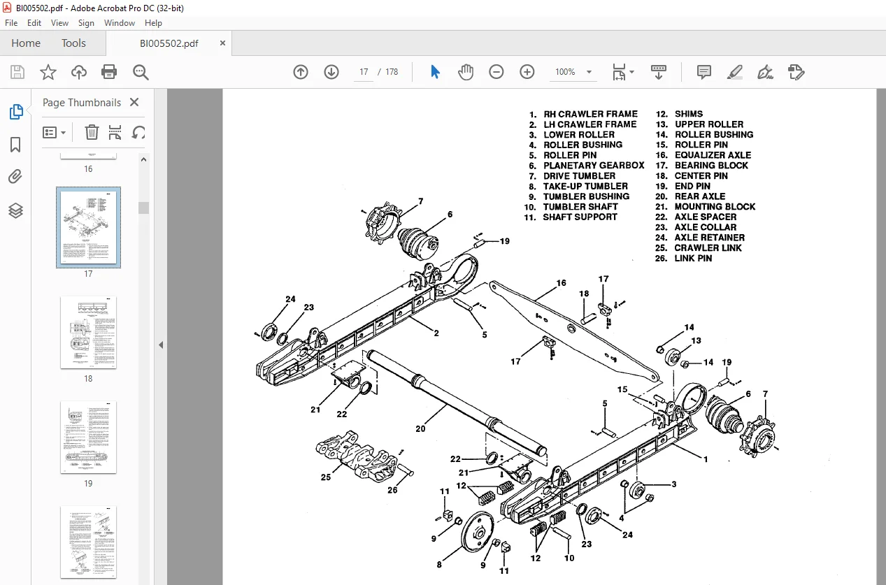
- The lower works provides a foundation for the mainframe and contains the necessary equipment to propel the drill. The mainframe includes the hydraulic system, main air system, and the machinery house. The machinery house encloses the majority of the mechanical· equipment necessary for the main air system, the hydraulic systems and electrical control systems. The machinery house is pressurized with filtered air to minimize dirt and heat build-up.
- The operator’s cab, mounted to the mainframe, includes the operator’s station, and encloses the majority of the controls necessary to operate the drill. The mast contains the drill pipe and drilling tools, the pipe racks, and the rotary and pulldown machinery. This manual consists of six chapters, each divided into sections. A table of contents is located in the front of the manual.
IMAGES PREVIEW OF THE MANUAL:
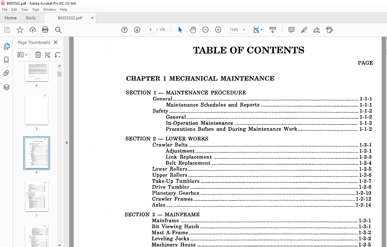
TABLE OF CONTENTS:
Cat BUCYRUS 59R ELECTRIC BLAST HOLE DRILL MECHANICAL MAINTENANCE MANUAL – PDF DOWNLOAD
CHAPTER 1 MECHANICAL MAINTENANCE
SECTION 1 – MAINTENANCE PROCEDURE
General 1-1-1
Maintenance Schedules and Reports 1-1-1
Safety 1-1-2
General 1-1-2
In-Operation Maintenance 1-1-2
Precautions Before and During Maintenance Work 1-1-2
SECTION 2 – LOWER WORKS
Crawler Belts 1-2-1
Adjustment 1-2-1
Link Replacement 1-2-3
Belt Replacement 1-2-4
Lower Rollers 1-2-5
Upper Rollers 1-2-6
Take-Up Tumblers 1-2-7
Drive Tumbler , 1-2-8
Planetary Gearbox 1-2-10
Crawler Frames : 1-2-12
Axles 1-2-14
SECTION 3 – MAINFRAME
Mainframe 1-3-1
Bit Viewing Hatch 1-3-1
Mast A-Frame 1-3-2
Leveling Jacks 1-3-2
Machinery House 1-3-5
House Ventilation Fan and Filter 1-3-6
Walkways and Ladders 1-3-6
Operator’s Cab 1-3-7
Operator’s Seat 1-3-7
Operator’s Controls 1-3-7
Ventilation Unit 1-3-7
Hydraulic Pump Drive 1-3-8
Cable Reel 1-3-10
Level Wind Drive Adjustment 1-3-10
Hydraulic Adjustments 1-3-10
Lubrication 1-3-13
Hydraulic Maintenance 1-3-13
Repair 1-3-13
SECTION 4 – MAST
Mast Structure 1-4-1
Mast Safety Sling 1-4-2
Rotary Gearcase 1-4-2
Drive Shaft Adjustment 1-4-2
Repair 1-4-3
Rotary Motor 1-4-8
Rotary Coupling ~ 1-4-8
BI005502
Rotary Shock Sub 1-4-9
Rotary/Pulldown Guide Frame 1-4-11
Guide Roller Adjustment 1-4-11
Repair 1-4-11
Pulldown Gearcase 1-4-15
Hoist Brake 1-4-20
Inspection 1-4-20
Brake Wear Adjustment 1-4-20
Replacement of Friction Discs 1-4-20
Disassembly of Magnet Body and Armature 1-4-21
Reassembly of Magnet Body and Armature 1-4-21
Pipe Racks 1-4-22
Tool Wrenches 1-4-23
Auxiliary Winch 1-4-24
Mast Braces 1-4-24
Repair 1-4-24
Adjustment 1-4-26
CHAPTER 2 HYDRAULIC SYSTEM
SECTION 1 – SYSTEM OPERATION
Cylinder Circuit Hydraulic System 2-1-1
Propel Circuit Hydraulic System 2-1-1
SECTION 2 – GENERAL MAINTENANCE
Hydraulic System Cleanliness : ~ 2-2-1
Oil Requirements 2-2-1
Oil and Filter Changes 2-2-1
Filter Maintenance 2-2-1
Weekly Maintenance Checks 2-2-2
Oil Reservoir Repairs 2-2-2
Leveling Jack Counterbalance Valve Pressure Relieving Procedure 2-2-2
Rear Jacks 2-2-2
Front Jack 2-2-3
Prestart Inspection 2-2-3
Hydraulic Systems Tests 2-2-4
Propel Pump Charge Pressure Check 2-2-4
Control Pressure Check 2-2-4
Propel Enable Valve and Low Speed Select Check 2-2-4
Jack Cylinder Check in Manual Mode 2-2-5
Flow Control Check · 2-2-5
Jack Cylinder Drift Test 2-2-6
Brake Release Pressure Check 2-2-6
Propel Brake Emergency Release Check 2-2-6
Propel Pump Main Relief Pressure Check 2-2-7
Crawler Function Check 2-2-7
Bit Viewing Hatch Check 2-2-7
Boarding Stair Check 2-2-7
Main Flow Valve Check 2-2-7
Breakout Wrench and Tool Wrench Check 2-2-7
Dust Curtain Cylinders 2-2-8
Dust Seal Slider 2-2-8
Mast Lock 2-2-8
BI005502
SECTION 3 – ROTARY SCREW COMPRESSOR
Description 3-3-1
Coupling Alignment 3-3-1
Paral1el Misalignment 3-3-2
Angular Misalignment 3-3-2
Start-Up Procedure 3-3-2
Shutdown 3-3-3
Controls and Instruments 3-3-3
Air Pressure Control System 3-3-3
Reduced Unloaded Horsepower Feature 3-3-8
Variable Volume Feature (Optional) 3-3-10
Lubrication System 3-3-11
Compression Oil System 3-3-11
Oil Specifications 3-3-11
Filling Oil System (Initial1y) 3-3-11
Oil Level Gauge , 3-3-11
Adding Oil Between Changes 3-3-12
Oil Change Intervals 3-3-12
Draining Oil System 3-3-12
Refilling Oil System 3-3-12
Compressor Oil Strainer and Filters 3-3-12
Compressor Oil Cooler 3-3-13
Compressor Oil Separator 3-3-13
Cold Weather Start System (Option) 3-3-14
Air Filters 3-3-15
Maintenance Schedule 3-3-16
Mast Brace Lock Cylinders 2-2-8
A-Frame Lock Cylinders 2-2-8
Mast Lock Constant Pressure Check 2-2-8
Mast Brace Constant Pressure Check 2-2-8
A-Frame Lock Constant Pressure Check 2-2-8
Mast Raise/Lower 2-2-9
Auxiliary Winch 2-2-9
Hydraulic Central Lube Drive Pressure Check 2-2-9
Window Guard Function Check 2-2-10
Water Injection Drain Valves Check 2-2-10
Water Injection Pump Function Check 2-2-10
CHAPTER 3 AIR SYSTEM
SECTION 1 – SYSTEM OPERATION
Main Air System 3-1-1
SECTION 2 – GENERAL MAINTENANCE
Main Air System 3-2-1
Intake Air Filter 3-2-1
Compressor Radiator
SECTION 3 – ROTARY SCREW COMPRESSOR
Description 3-3-1
Coupling Alignment 3-3-1
Paral1el Misalignment 3-3-2
Angular Misalignment 3-3-2
Start-Up Procedure 3-3-2
Shutdown 3-3-3
Controls and Instruments 3-3-3
Air Pressure Control System 3-3-3
Reduced Unloaded Horsepower Feature 3-3-8
Variable Volume Feature (Optional) 3-3-10
Lubrication System 3-3-11
Compression Oil System 3-3-11
Oil Specifications 3-3-11
Filling Oil System (Initial1y
APPENDIX A4 – LUBE BENCHMARKS
MPG – Multi-Purpose Type Grease 4A-l
ACSL – Air Compressor (Screw Type) Lubricant 4A-2
DPTL – Drill Pipe Thread Lubricant 4A-3
MPO – Multi-Purpose Oil 4A-4
OGL – Open Gear Lubricant 4A-5
RGL – Regular Type Gear Lubricant 4A-7
RWRL – Running Wire Rope Lubricant 4A-IO
Special Requirements 4A-IO
HYDO – Hydraulic Oil 4A-ll
APPENDIX A5 – RECOMMENDED PROCEDURES FOR MAINTENANCE WELDING OF
PRINCIPAL STRUCTURES ON BLAST HOLE DRILLS
General 5A-l
Maintenance Welding 5A-l
Structural Materials 5A-l
Welding Electrodes 5A-2
Preheat Requirements 5A-2
Removal of Cracks 5A-3
Weld Groove Preparation 5A-4
Drill Pipe Welding 5A-4
Welding Technique 5A-5
Weld Inspection 5A-5
Repair of Broken Parts 5A-5
APPENDIX A6 – PREVENTIVE MAINTENANCE CHECKLIST
Level 1 Inspection 6A-l
Level 2 Inspection 6A-5
Level 3 Inspection 6A-7
APPENDIX A7 – SPECIAL
Questions? Email us: [email protected]
https://vimeo.com/864390674?share=copy
PLEASE NOTE:
- This is the SAME manual used by the dealers to troubleshoot any faults in your vehicle. This can be yours in 2 minutes after the payment is made.
- Contact us at [email protected] should you have any queries before your purchase or that you need any other service / repair / parts operators manual.
S.M